The Schroeder Gotham Hobby Deezil Engine
 |
Click on images to view them in larger size and more detail.
| Name | DEEZIL | Designer | Winston (?) |
| Bore | 0.473" | Stroke | 0.708" |
| Type | Compression Ignition | Capacity | .124 cuin (2.039cc) |
| Production run | Lots | Country of Origin | USA |
| Photo by | Ron C | Year of manufacture | 1947-1955 |
Background
The Gotham Hobby "Deezil" is certainly an engine with many stories, old and new.
The original was produced by two of the founders of AHC (America's Hobby Center). The four brothers Winston had founded AHC before WWII (that's The Big One to you modern pups  ). When America entered the war, two of the brothers went off to do their bit and were paid out for their share in the business. The story goes that while they survived and returned, the two who'd stayed at home were not interested in letting them back in, so they started Gotham Hobby in opposition. At this time, AHC was producing a number of very low priced (and low quality) engines. To compete with these, Gotham Hobby produced the "Deezil". This was advertised in MAN from about 1947 on, fully assembled for $4.95 including accessories. As time went on, the Deezil was offered at ever decreasing prices, in many forms including a fully machined, ready to assemble kit. By 1955, the price was down to $1.95!
There are many stories relating to poor quality of the Deezil with some owners claiming the engine would never run, and others saying it ran just fine! Both claims are completely believable as the cylinder was fabricated by brazing the mounting flange plate onto a piece of tube. That's ok as long as it is done with precision, but get the orientation of the flange the slightest bit off and friction is going to make running very difficult. Les Stone provides this first hand account:
"I fell victim to the Gorham Hoax many years ago. I was watching the magazines until the price finally fell to $2.95 for one engine, I jumped on that one and when it arrived, proceeded to try staring it for a couple of days until my arm felt like it was about to drop off."
I suspect the comparative rarity of "diesel" (or more correctly, "compression ignition") engines in the USA played a part too. Getting the feel for a diesel is an acquired skill. It's easier if there's someone around who knows what they're doing to start it for you and find the settings the first time.
Methanol was readily availability in the USA. In Europe, the UK and Australia/New Zealand, it was rare and expensive. The result was that modellers in the USA developed skills with glow motors while most of the rest of the world developed diesel starting skills.
If a beginner strikes trouble operating an engine, they need a local expert they can turn to who knows about that type of ignition. If none is available, then faced with failure and frustration, it's easy to place the blame on the most obvious source: the maker of the engine. Poor Deezil. And poor Gotham Hobby too. They folded, and all those Deezils that were obviously no good went to the tip, making the Deezil a comparatively rare engine today.
Design wise, the Deezil is a good example of a long stroke, side port, 2cc capacity, compression ignition engine. It should exhibit all the operating characteristics of such an engine. These are typically: easy starting, docile, wide operating range (rpm) although with a relatively low top end, and high torque to turn big props. Built right, that's exactly what it does. Recognizing this and playing on the rarity, Gordon Burford, Australia's leading engine designer and manufacturer, made a limited production run of replicas in the 1980's. Gordon was also able to play on the novelty of a Deezil that would actually run! This was followed by a Chinese copy by CS which threatened large volumes, so Gordon left the market to them and went on to other designs.
Build Your Own (Runnable) Deezil
 The other Deezil, and the one presented here, is the Roger Schroeder reproduction. Roger presented his version as a series of articles in Strictly Internal Combustion (SIC) magazine, beginning in issue 39 for June/July 1994. The articles span issues 39 through 43 and are still available from the publisher and editor, Mr Robert Washburn, 24920 43rd Ave S, Kent WA 98031, USA. Roger does not normally do full size reproductions to circumvent any potential problems with his castings being used by unscrupulous persons. But in this case, he went full size, making his sand casting pattern (the originals were die cast) from an actual crankcase. Roger figured you should be able to tell a repro Deezil easily; it would run!
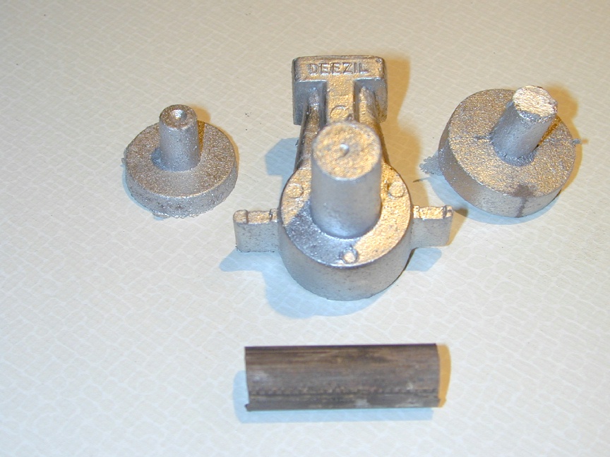
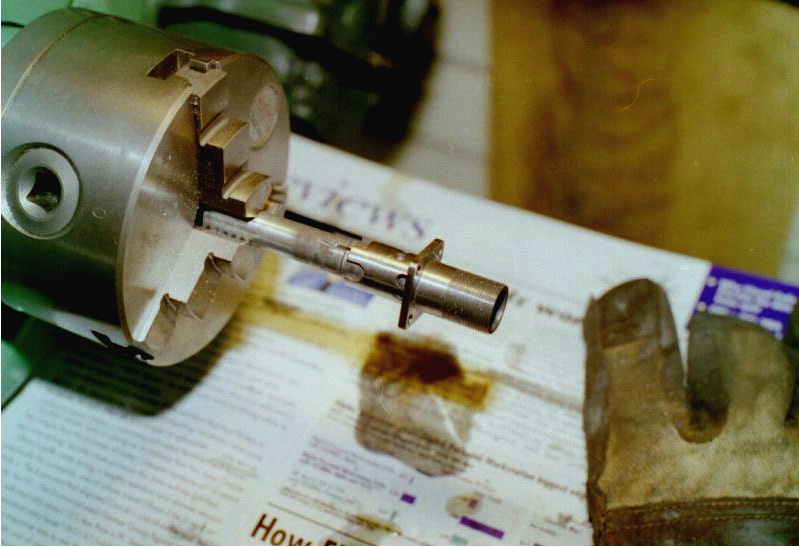
These are the parts supplied in Roger's kit. They are (clockwise from center top) the crankcase casting, the rear cover, a length of bronze for the main bushing and the tank cover. Also supplied, but not shown, is a complete set of CAD drawings and step by step machining instructions.
The other Deezil, and the one presented here, is the Roger Schroeder reproduction. Roger presented his version as a series of articles in Strictly Internal Combustion (SIC) magazine, beginning in issue 39 for June/July 1994. The articles span issues 39 through 43 and are still available from the publisher and editor, Mr Robert Washburn, 24920 43rd Ave S, Kent WA 98031, USA. Roger does not normally do full size reproductions to circumvent any potential problems with his castings being used by unscrupulous persons. But in this case, he went full size, making his sand casting pattern (the originals were die cast) from an actual crankcase. Roger figured you should be able to tell a repro Deezil easily; it would run!
These are the parts supplied in Roger's kit. They are (clockwise from center top) the crankcase casting, the rear cover, a length of bronze for the main bushing and the tank cover. Also supplied, but not shown, is a complete set of CAD drawings and step by step machining instructions.
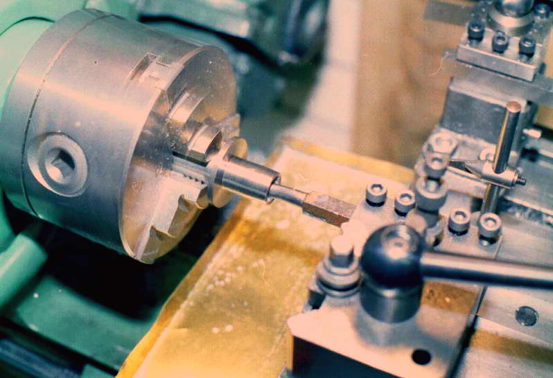 In this photo, the upper portion of the cylinder has been turned to size, but not screw cut for the cooling muff. The cylinder blank has then been reversed so the lower portion, underside of mounting flange and cylinder bore can be cut at one setup to ensure things that should be at 90 degrees to each other are! The shot shows a boring tool cutting from bottom to top. There's always some spring-back, so cutting this way places any reduction in bore where we want it: towards the top of the cylinder. The cylinder can then be transferred to the mill to square up the mounting flange, drill the mounting holes and machine the ports.
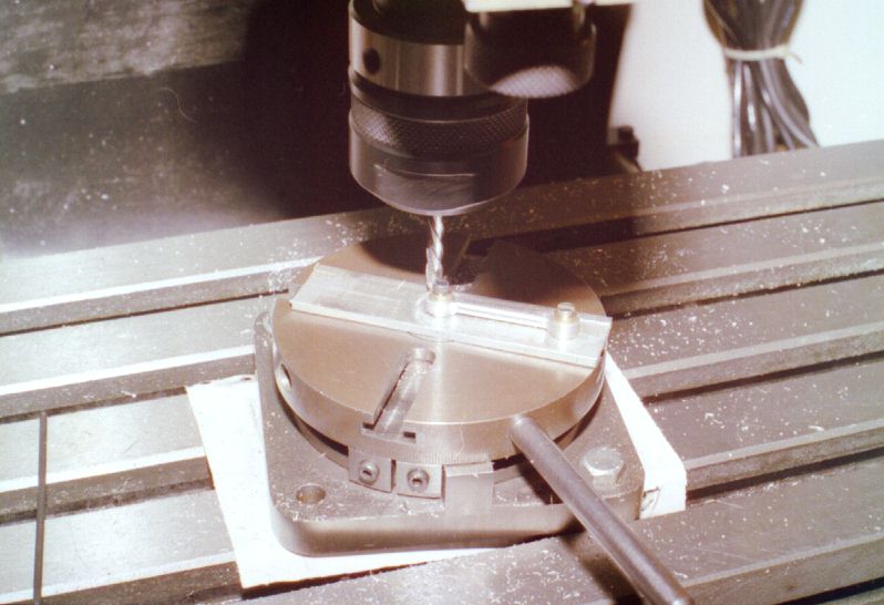
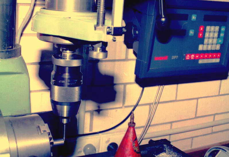 Here we are preparing to cut the ports. The cylinder needs to be aligned with the table axis using an engineers' square on the rotary table and mill table edge. Next an "edge finder" is used to center the cylinder under the spindle and to locate the underside face of the mounting flange which forms the datum for positioning the port holes. The edge finder in use here is shop-made to a George Thomas design that appeared in Model Engineer. The digital readouts show it is very accurate.
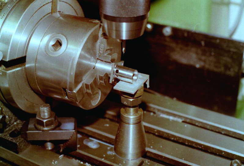 During drilling, the cylinder is supported by a bottle jack to prevent drilling loads form deflecting the cylinder and allowing the drill to run off. All holes are spotted first with a center drill then drilled two number sizes undersize, followed by the final size. The intent is to bring the hole to an accurate final size with the minimum of burring (which is difficult to remove as it is inside the bore). Any burr on the ports will chew up the expanding lap, and maybe the cylinder, so this precaution is well worthwhile. After the ports are finished, the cylinder can be swapped end for end and the upper portion completed by cutting the screw thread for the cooling jacket. It does not matter if a little concentricity is lost in this operation, but be sure to use some shim around the part to protect the finish from the jaws (I keep a stock of aluminum drink can around for this purpose), and clamp the jaws only enough to grip the part to avoid distorting it.
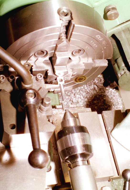
 The cylinder is completed by lapping the bore using a simple expanding lap, charged with diamond paste. m5/m5 this lap is expanded it becomes very slightly conical, which is good provided we arrange the resulting tapered bore to be narrower at the top. This photo shows the cylinder on the lap with the lathe bed protected by paper. The lap is rotated slowly (around 400 rpm) and the lap adjusted to provide light drag--nothing approaching what will snatch the cylinder out of you hand. The cylinder is stroked up and down the lap, never allowing more than 1/4 of the lap to emerge at either end. When the lap feels loose, stop, expand slightly and continue until looking up the bore shows a uniform dull grey with no sign of tool marks. You should also notice that the lap feels tighter at the top of the stroking indicating you have the desired taper of between 0.001" to 0.0015" from where the piston sits at top and bottom dead centers. Wash out the cylinder thoroughly in kerosene (or better, use an ultrasonic bath, if you have one). Eagle eyed readers will notice the cylinder is posed exactly the wrong way around here (it was also a long time ago, I may have not known exactly what I was doing as well
  ).
).
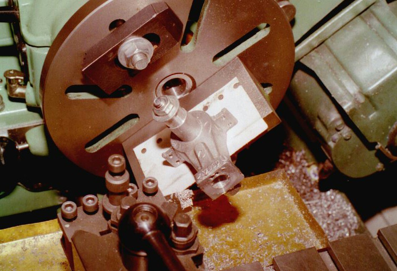 Machining of the case follows the normal practice: first the crankshaft cavity is bored and screwcut for the backplate, and the rear face skimmed to length providing a reference surface perpendicular to the bore. The hole for the shaft bearing is then cut and the case and chuck transferred to the rotary table under the mill so the mounting holes in the lugs and the transfer holes in the front of the cylinder extension can be drilled. The back to the lathe to part off from the chucking stub at the front. The last step seen in this photo is to mount the cylinder on an angle plate, using the rear face to align it for the cylinder bore. This insured that both bores are at right angles. A plug is inserted in the end to the case to center the mounting bolt allowing us to measure from the top of the case to the top of the bolt to establish the "deck height". A more reliable method is to use a close fitting plug in the case with a flat milled on top and measure to this flat. Simple calculation from measurements will provide the axis of the cavity. This is more reliable than trying to measure to the top of a small diameter surface like a bolt. The bore will break into the transfer ports drilled earlier. When this happens, the boring tool will be drawn off line, so take light cuts after this happens to keep the bore circular, running the tool through several times at the same setting. We want a close sliding fit on the cylinder to ensure there is no gas leakage between the ports. Also note the counterweight bolted to the face plate to reduce vibration which can also impact the geometry of the cut (for the worse, naturally).
 These shots show the con rod being machined. The holes have been drilled and reamed at the same set-up to ensure they are parallel to each other, then the rod blank setup between centers to turn the center section. In the other picture, the rod has been mounted to a plug in the middle of a small rotary table (another George Thomas design) to profile the ends. This is a lot of work--making the little plugs to fit in the center of the table and all--I would no longer do it this way. Instead, I'd place the rod on a close fitting spindle set vertical in the mill vyce. The spindle is capped to prevent the rod moving vertically, then an end mill brought into contact with the end that is rotated by hand. With care, this gives better and faster results. The care required is as the cutter approached the rod shank; there is a danger of it "grabbing" the rod and milling into the shank--which can't happen using the rotary table setup seen here. You pay's your money and take's your chances!
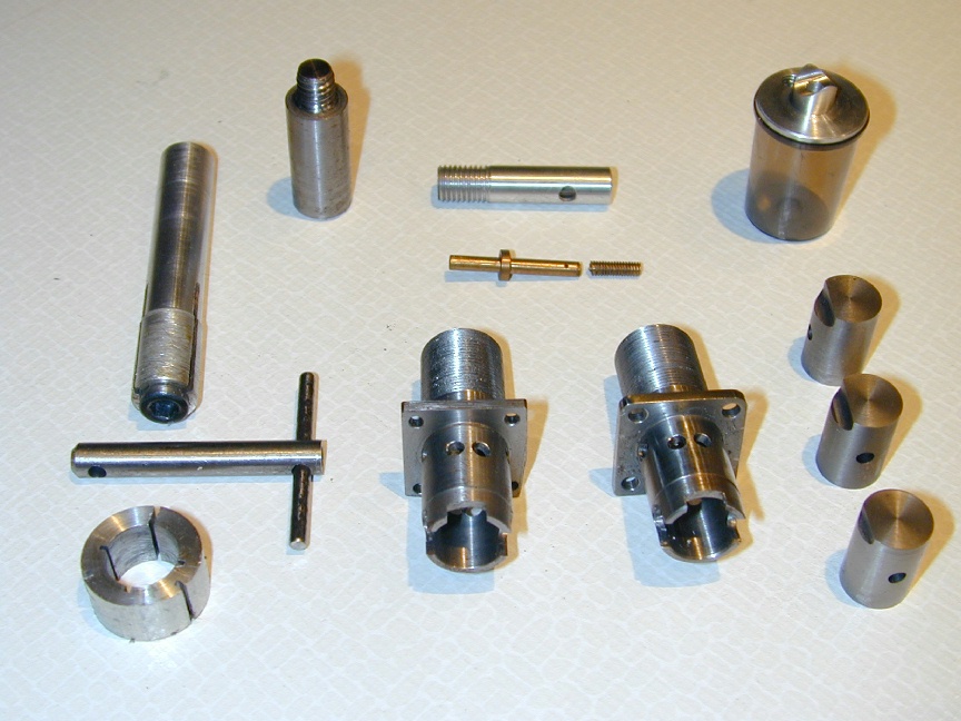 Unfortunately, I'm not out of the "one for me, one for the scrap box" phase yet. This photo shows the tools and jigs I made for the Deezil on the left and the stuff-ups on the right. Of particular note are the three pistons. All three are perfect, except that two of them have the baffle milled 90 degrees to where it should be! These are pistons #1 and #3.
On milling the baffle wrong on piston #3,
I recall saying "I don't believe I just did that?" (or something like that).
Piston #2 just got lapped a little too much for cylinder #3. Cylinder #2 was a shade too loose in the crankcase.
I don't want to talk about cylinder #1.
The tank assembly (top right) was an experiment using a deodorant spray cap. Although it looks ok, the plastic is too brittle for actual service. Caps from yuppie water bottles are perfect (as are Aunt Jimima's Syrup bottle caps, if you live in the USA).
Unfortunately, I'm not out of the "one for me, one for the scrap box" phase yet. This photo shows the tools and jigs I made for the Deezil on the left and the stuff-ups on the right. Of particular note are the three pistons. All three are perfect, except that two of them have the baffle milled 90 degrees to where it should be! These are pistons #1 and #3.
On milling the baffle wrong on piston #3,
I recall saying "I don't believe I just did that?" (or something like that).
Piston #2 just got lapped a little too much for cylinder #3. Cylinder #2 was a shade too loose in the crankcase.
I don't want to talk about cylinder #1.
The tank assembly (top right) was an experiment using a deodorant spray cap. Although it looks ok, the plastic is too brittle for actual service. Caps from yuppie water bottles are perfect (as are Aunt Jimima's Syrup bottle caps, if you live in the USA).
The tooling shows the internal lap for the cylinder, per Roger's instructions and my own style external lap for the piston. In use, it is mounted in a tailstock die holder, which provides the adjustment. This is mounted in the lathe 3 jaw chuck. The piston is mounted on the little T-Bar handle for stroking in and out as the lathe revolves at low speed with lots of oil (and paper to keep the gunk off the lathe bed). I use diamond lapping paste which gives good results, although I follow up with a bath in the ultrasonic cleaner to ensure little or no lapping particles remain in the piston and liner.
Conclusion
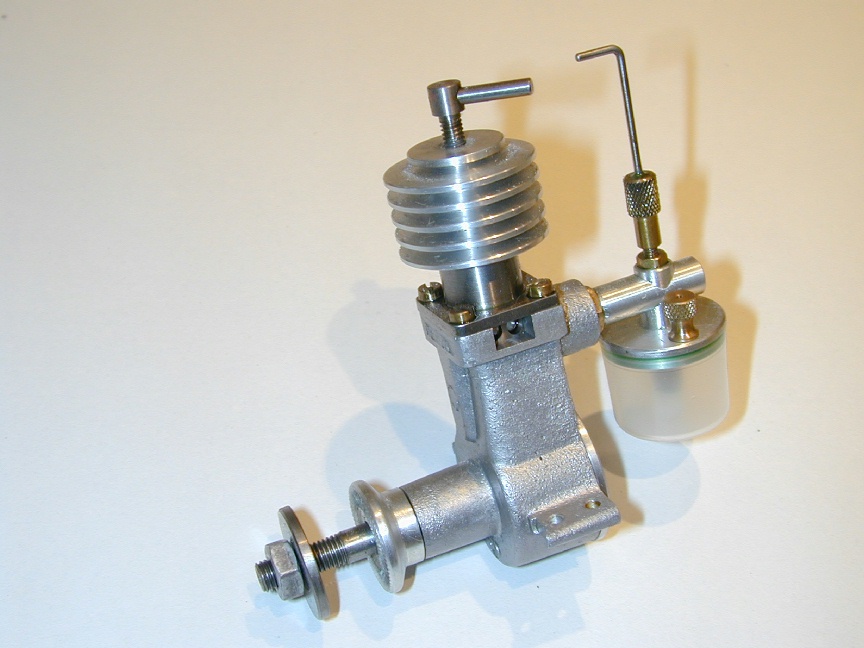
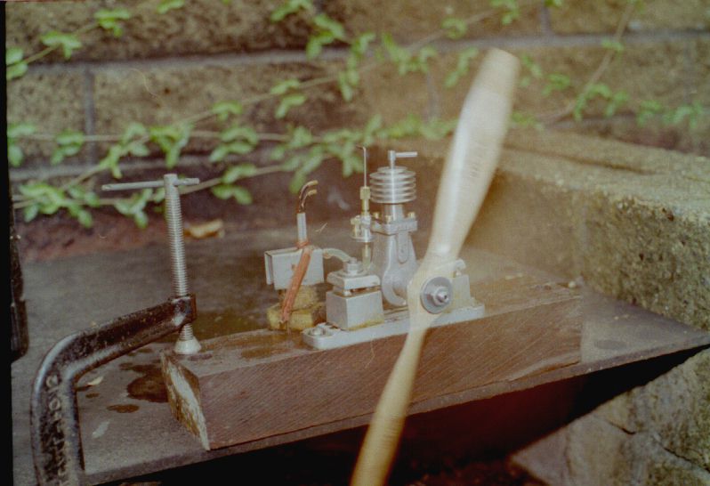 The Deezil reproduction is an excellent running engine. It's size, neither so small to be like watch making, nor so large that mistakes are time consuming and expensive, make it a fine choice as a beginners' project and success is almost assured. Here it is on its first outing (with yet another of my justly outrageous and embarrassing fuel tank lash-ups). In this shot it is spinning a 12x6 wood prop to get some extra flywheel effect while it is still tight. After a few tanks at a rich setting, the needle can be wound in the comp screwed down and progressively smaller props fitted. But one of the joys of these old, long stroke diesels is their torque and ability to spin ridiculous diameter props. Plus the smell—pure ambrosia!
![]()
