Cirrus Construction Log: Crankshaft
Created: March 2005
Updated: April 2005
The crankshaft for the Cirrus is a perfect example of a conventional 4-throw crankshaft, where the outer pair of throws are oriented at 180 degrees to the inner pair. For this engine, it is supported by three ball races, two at the front, one at the rear, and a split, bronze shelled bearing in the center. This design is typical of most four cylinder, in-line internal compustion engines. Numbering the cylinders from front to rear, the firing order imposed by the Cirrus cam is 1-2-4-3, although others are possible.
Primary reciprocating forces for this configuration cancel out, so the engine does not tend to jump up and down (in the plane of the cylinders) as it runs. The fore-aft pairs arrangement also cancels out the primary rocking couples present in two cylinder in-line engines, but secondary (ie, second harmonic) forces will sum up to a problem in a "full size" engine, requiring something like the Lanchester balancer. Aircraft engine designers tend to dislike this solution due to the weight penalty and prefer designing the components so the harmonics do not correspond to resonances in the normal operating speed range, where possible (some engines had little yellow arcs inscribed on the tachometer face indicating the speed range which which was to be avoided). At model sizes, we can just ignore it all.
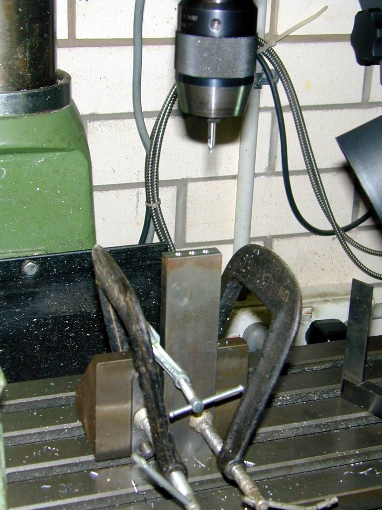 The conventional way to turn up such a shaft is between centers, so construction starts by truing up the two ends of the blank, marking up, then center drilling each end on the axis and throws so that the pairs of centers are in line and parallel to each other (and centered in the blank thickness). This is easy enough with a DRO (digital read-out) on your mill, and some simple jigging involving an angle plate and G-clamps as seen here.
The blank was cut from a lump of cold rolled steel bar 1/2" thick. Surprisingly, this material machines quite well, but the rolling process locks a lot of stress into the "skin" of the steel (so I've read). As parts are cut away, these stresses will warp the stock. This was verified unintentionally. The stock was oversize, width wise. After drilling the centers, it was gripped in the mill vise and some excess milled away from one edge. Removing it to flip for milling the other side, I noticed the unmilled side was now distinctly banana shaped when laid against the top of the vise (although the milled part was flat). Milling the other face fixed that, but left the first milled face very slightly bent!
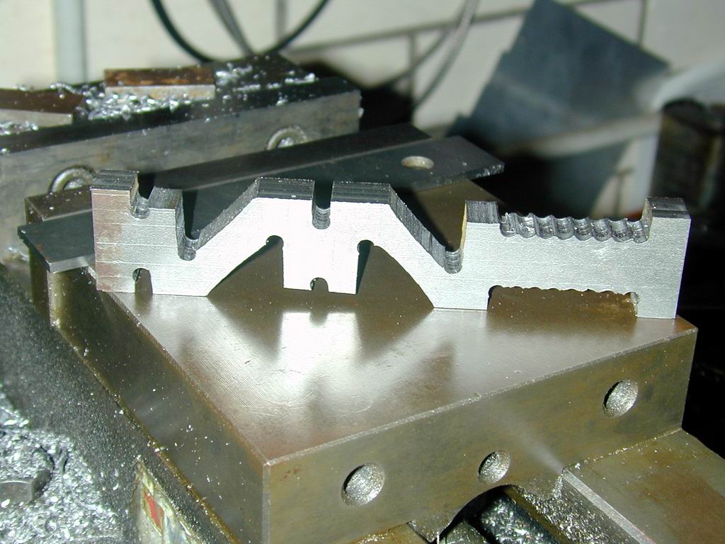 This is not as much a problem as it may seem as long as enough excess is left to be machined away after all the warp inducing cuts to the "skin" have been made. The 100% fix would be to "normalize" the blank at this stage by heating to cherry red, and air cooling, although at the size involved, this would probably be overkill. Note the "throw pieces" at either end containing the offset centers for turning the crankpin journals. These will be cut away later before the outer journals are turned. The downside of all the metal removal required to get the stress out is that it's about imposible to fit spacers between the shaft cut-outs to prevent clamping forces from the lathe centers from distorting the shaft. The answer is to adjust the centers to be firm, but not tight (and pray a bit).
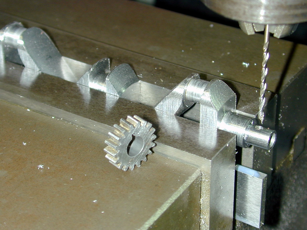
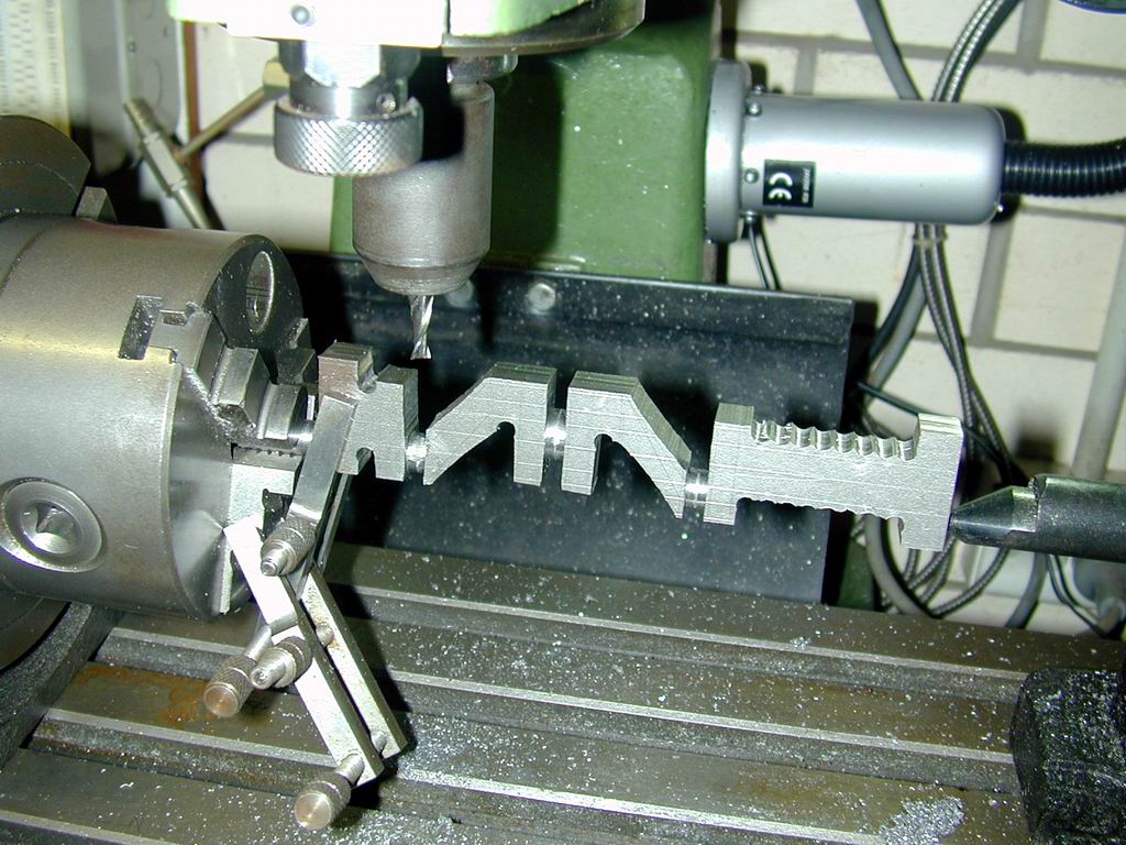 The tool needed to finish the crankpin and center journals is necessarily thin, with a lot of overhang. Such tools are a bad choice for interrupted cuts. So to prevent a lot of re-sharpening and operator stress, the crank was setup under the mill and a 6mm slot drill used to nibble away the square corners. This also allowed the precise center distances of the journals to be milled relative to the center journal. The metric tool was chosen as the finish length of the journals was to be 0.256". A 1/4" cutter would be too close for comfort (for me), but 6mm is 0.236", leaving a nice length for facing back.
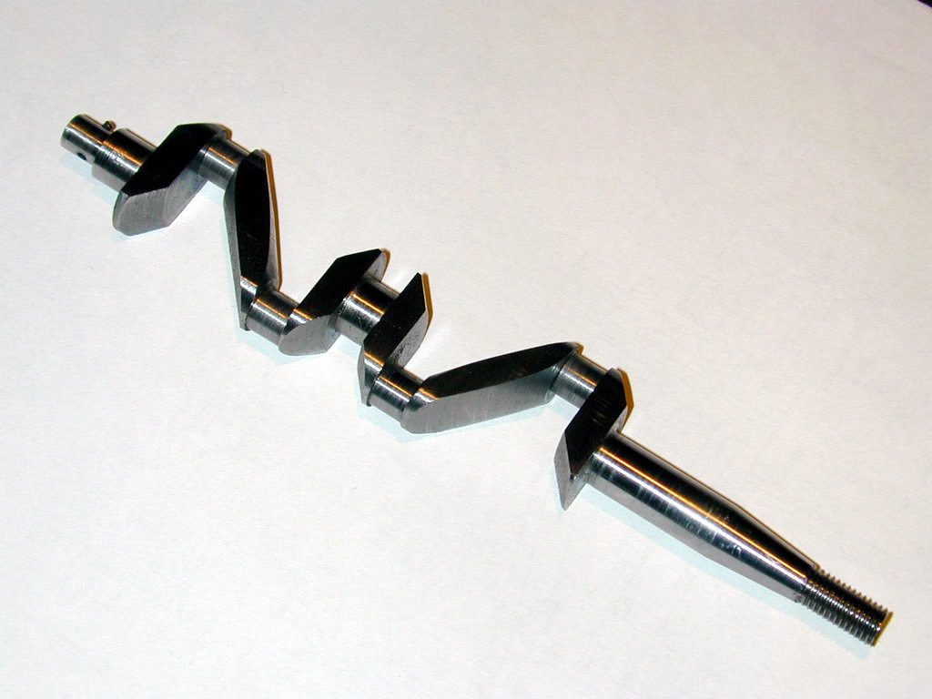
With all journals, including the front and rear ones between the "throw pieces" and webs roughed out circular but oversize, the remaining work is accomplished between centers in the lathe.
Caution! While working with the offset throws, after changing a setup, ALWAYS rotate the job through one turn by hand before applying power to ensure nothing moving is about to disasterously clobber something stationary.
If I'd not done this, I would have had at least one noisy, expensive and embarassing surprise.
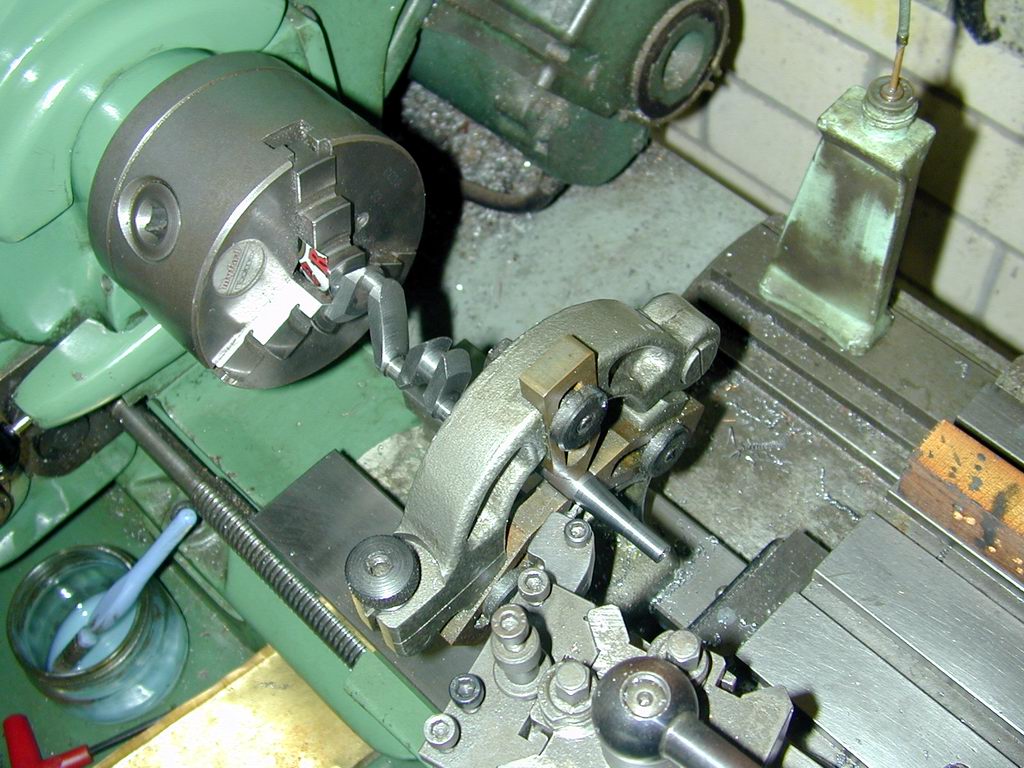
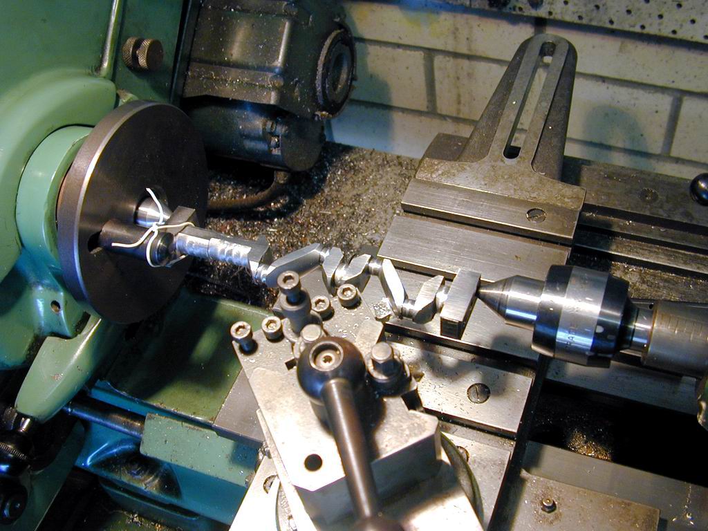 To form the angled crank webs, the top slide was set over and fine cuts in backgear made to clean up down to the marked out lines. The SIC article says do all the ones you can reach, then angle the other way and do the others. I just set the single angle seen here and swapped the shaft end for end, and center pair for pair as required. That worked perfectly, but I really should have formed the journals first, then done the angle turning to achieve accurate placement of the angled webs. That way I could have avoided a lot of (imperfect) marking out too. The end result is acceptable, but not faultless. I'm almost tempted to make a new shaft—almost
  .
.
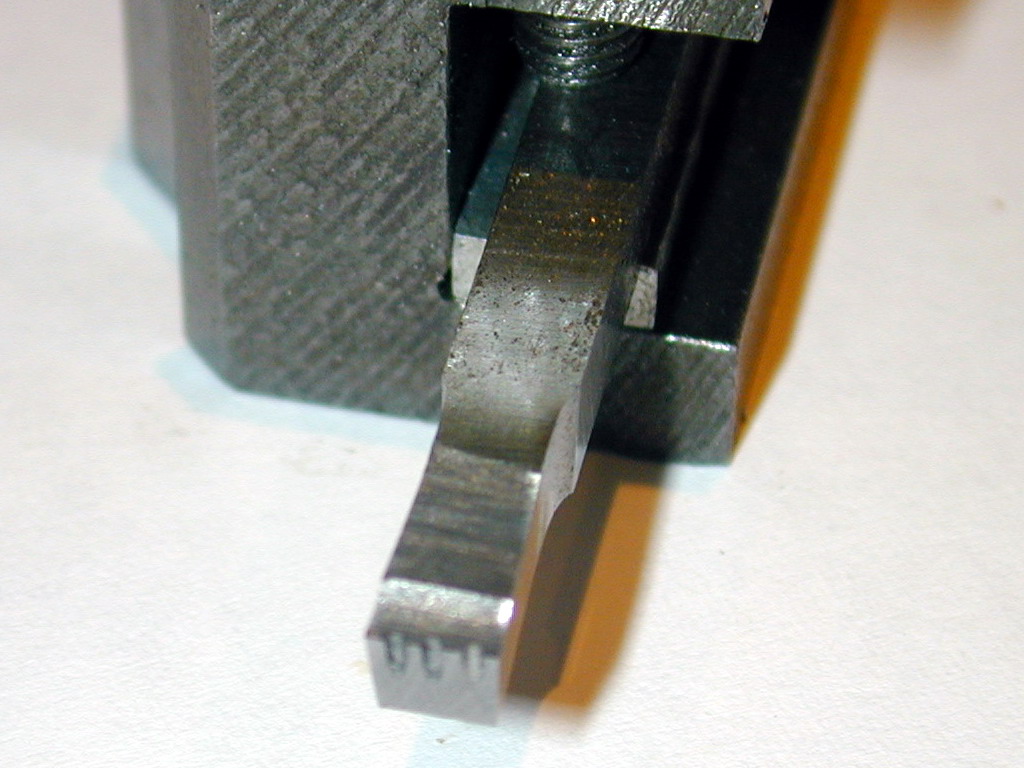
The best way to form the journals is with a tool that can be traversed a little between the throw webs. Following a tip I read in an old SIC, the end of the tool has a series of vertical grooves cut in it, making it like a ganged set of parallel parting blades. Three slots were cut in the end of a 3/16" square HSS side relieved tool using a Dremel part-off disk. These disks cut about 0.025" wide, so this leaves four cutting edges about 0.028" wide. As only light cuts will be made, the cuts don't need to be very deep. The narrow tips will easily penetrate the surface (which a 3/16" wide tip would not), then as the tool is traversed over the 0.068" of the free space, each cutter overlaps the work area of its neighbour. The finish is real good, and the cutting forces are remarkably less that those required by a "solid" parting blade. This means you can shave as little as one thou off the pin diameter with total ease and control.
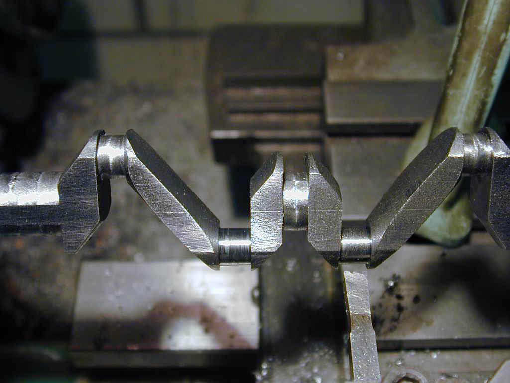
The position of each journal is established by centering the tool in the center gap, then using the Myford's calibrated leadscrew handwheel to wind the carriage to the center of the journal being turned. The compound slide is zeroed there, with backlash taken up towards the headstock. This enables one web face to be precisely positioned. The other can then be cut relative to the first. Each journal was finished to 0.295" diameter, then polished with a strip of 600 grit glasspaper backed up on a 1/4" piece of tool steel with plenty of oil. The numbered rods were individually fitted to their throws and "run-in" using "Brasso" polish as a lapping compound, progressively tightening the rod cap until the rod spun freely (but not loosely).
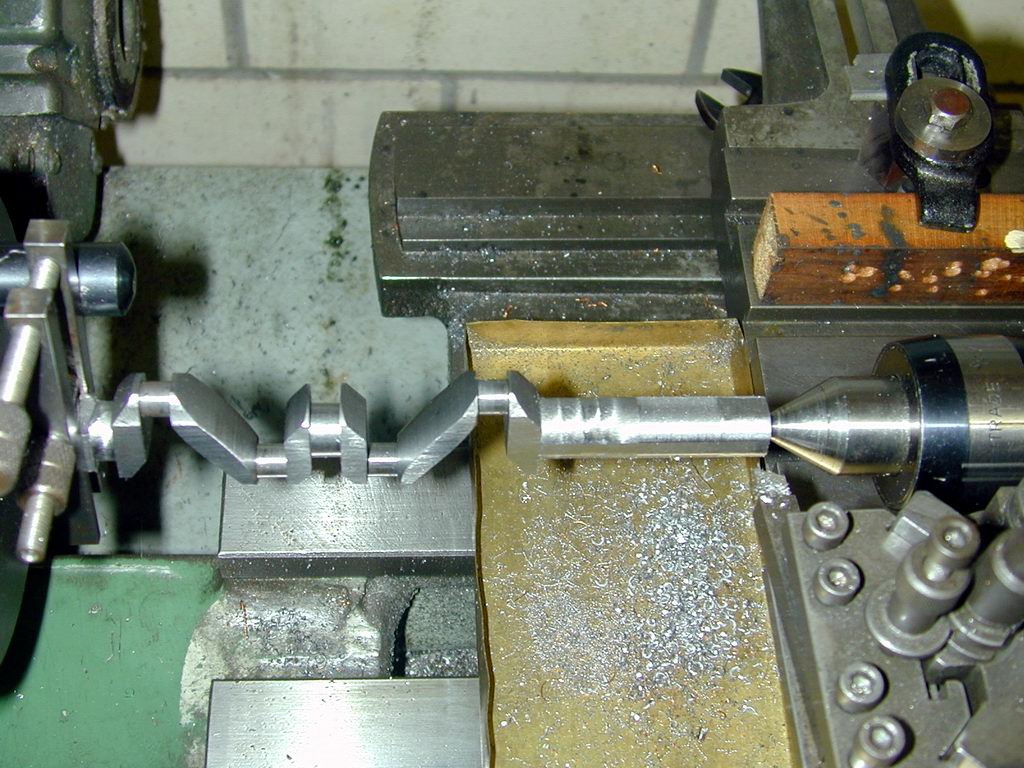
Once the journals for the conrods were finished, polished and "run-in" to their individual rods, the offset centers were cut away and the main shaft journals turned. To start with, the fore, aft, and center journals were roughed to about 0.025" above the finished size. Then they were finish turned in order: center, aft, front. On the front journal, the taper for the prop driver had me tossed. There was just no way to set over the compound slide 5 degrees and not have it hit something. Finally it dawned on me (a definite doh! moment) that the centers could be used to setup the fixed steady, then the shaft could be gripped in the 3 jaw chuck and supported by the steady to turn the taper.
Luckily I'd decided to finish turn the front shaft (which rides in a pair of ball races) last, so the fixed steady is not contacting a finish turned journal. The SIC plan for the shaft itself does not specify the taper (in fact, a number of dimensions have to be derived from others). The prop driver drawing, while missing two diameter dimensions, does manage to specify 10 degrees as the taper. This does not match the apparent slope from the given crank dimensions (x = 0.062, y = 0.625, hence angle = ATAN(.062/.625) = 5.7 degrees). I happened to have a 10 degree D bit reamer, so went with that, even though it increased the length of the tapered portion by over 1/16" of an inch. Doing it over, I'd make a 12 degree reamer and decrease the taper, as 10 degrees means the shaft journal and taper transition falls inside the nose of the crankcase—but still before the oil seal and front ball bearing. Incidentally, while finishing these surfaces, I found a tool with a very generous nose radius (about 0.025") gave an outstanding finish on the cold rolled steel at my lowest non-backgear speed (about 250 RPM). Using a sharp knife tool with a minimal nose radius, I had to go slower (in backgear) to get anywhere near the same finish. Amazing.
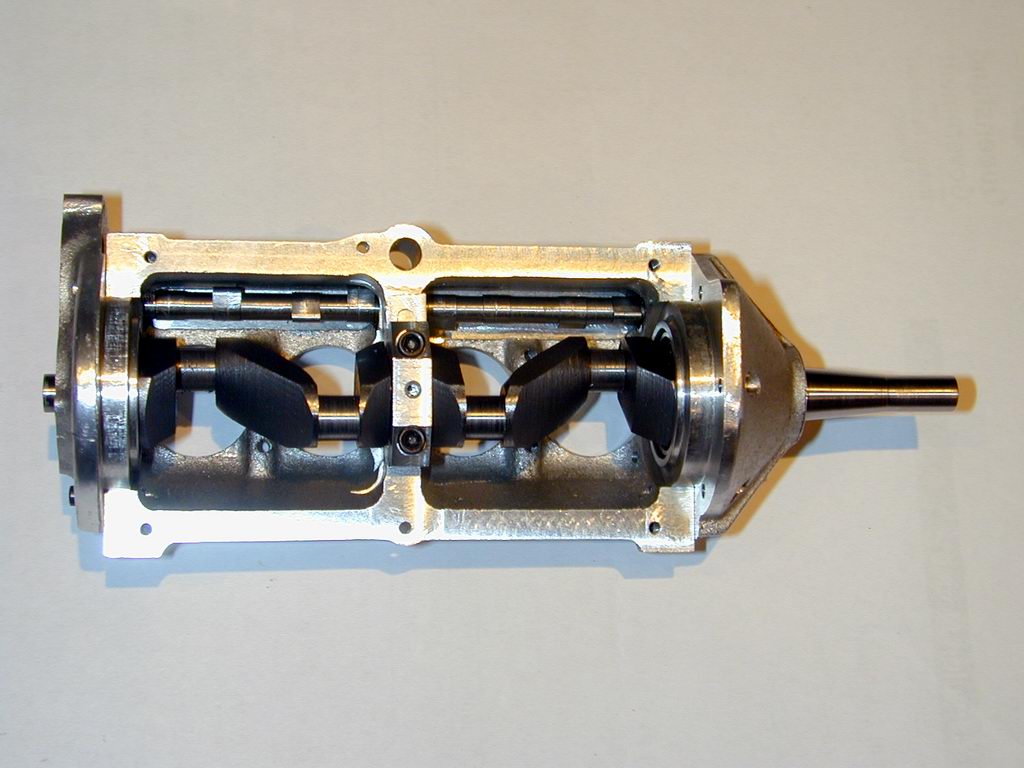 Trial fit time. The journals that ride in the ball races are finished to a sliding fit inside the race (about 0.2745"), Before finishing them, the distance between the inner crankshaft support bearing and the ball race faces was carefully measured with a telescoping bore gauge (easy to do with the bottom of the case removed. The 'outside' faces of the fore and aft crank webs were cut to within a five thou of the measured dimension and the shaft trial fitted. It spun beautifully with the end plates loose, showing that the fix applied to the rear casting described in the Cirrus Crankcase Page had been 100% effective. The faces were then adjusted incrementally using feeler gauges to figure out how much had to come off so that with the crankshaft fully forward (as if under thrust load), the center bearing was central on its jounal, and the rear ball race had 0.004" gap to the rear web face with the front and back plates fully tightened home.
With everything now finished to size, the last jobs are to cut the thread for the prop nut, and for the keyway for the cam drive gear. The shaft thread is the "standard" UNF 1/4-28. My preference for any thread over 3/16" major diameter is to screw-cut the thread to almost full theoretical depth, then use an adjustable button die to clean-up the form. The thread depth for 1/4-28 is 0.025", so it was cut to 0.022" deep using the topslide set over by one-half the thread included angle, minus one degree (ie, 29 degrees). This tool room trick is described in George Thomas' Workshop Manual and described in the December 2004 Editorial page. The almost fully formed thread ensures that the button die has a good thread to follow, ensuring it will cut a straight, clean thread. Start with the die opened out wide. Test the fit of a nut, and close up incrementally to achieve a free, but not loose fit.
 The timing drive gear key is a simple 1/16" drill rod peg. It is positioned to lie in the plane of the crank throws and will be vertical when the #1 and #4 throws are at TDC. Drilling this hole is the final operation on the crank, so I was feeling pleased to have reached this point without making any start-again disasters. Naturally that was a bad thought to think at this time. I'd planned to drill almost to the other side, neglecting that fact that the hole would break out into the center drilled into the end of the shaft. To drill small holes accurately to size, the general rule is two number sizes smaller, then clean up to size. So that's #54, followed by 1/16". Naturally the "Quality Asian Import" drill broke off as it broke thru. Grrrrr. So the shaft was turned over and drilled thru from the other side so the broken tip could be punched out. Lesson learnt for the umpteenth time: feed small drills very slowly as they are about to break out of steel, and avoid Quality Asian Import drills!
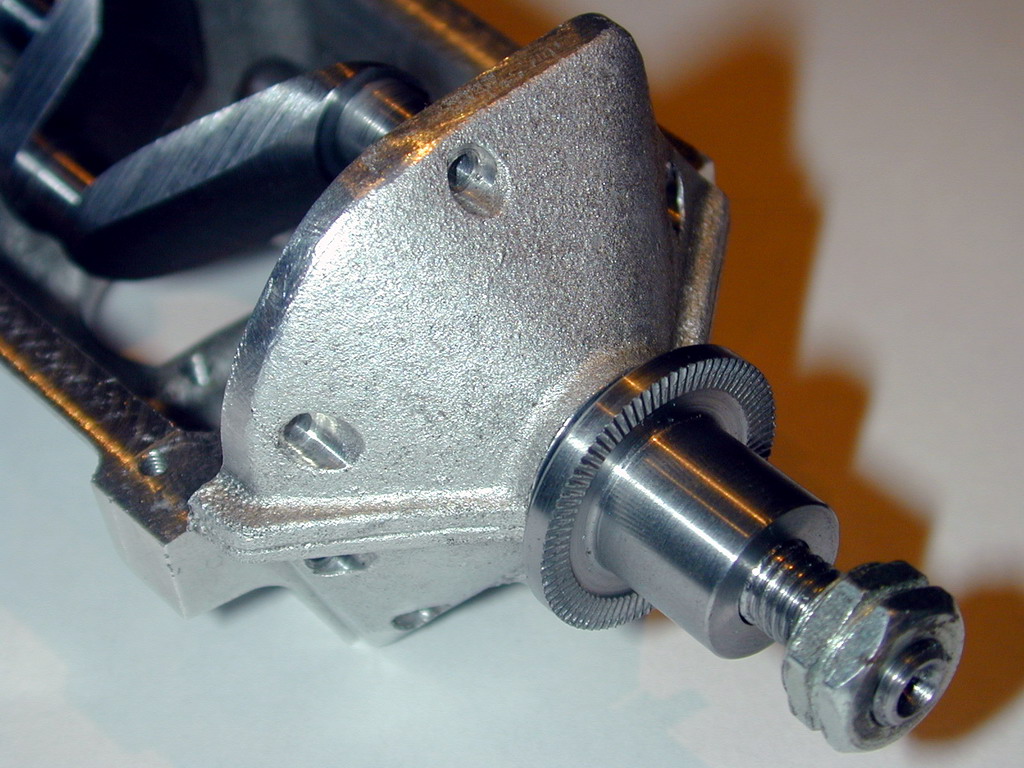 The prop drive washer as drawn in the SIC Cirrus plan is missing a couple of dimensions for the major and central hub diameters. It also lacks any face knurling. As dimensioned, the central hub is so long (9/16") that it would poke out the front of your average 12x6 prop, making it hard to cinch up the prop (without a cup shaped prop washer). I reduced the boss length to 15/32" and measured the plan for the missing dimensions. This would make the major diameter 1", and the boss diameter 5/8". These seemed a bit excessive, so I reduced them to 7/8" (the average size of a 12" prop hub), and 1/2" respectively. The latter is the same size as the "flying" Morton M5 prop hub, allowing me to interchange props. With a prop bolted up and the hub drawn up onto its taper, I can now waste countless hours spinning the prop and watching the shaft whirl in it's bearings. Totally useless, but very satisfying!


This page designed to look best when using anything but IE!
Please submit all questions and comments to
[email protected]
Copyright (c) Ronald A Chernich, 2004-2005. All rights reserved worldwide.