Cirrus Construction Log: Crankcase
 THIS PAGE UNDER CONSTRUCTION
Created: Feb 2005

Work on the crankcase began in about 1996 using co-ordinate drilling and boring on the mill to position all the holes—DRO's are wonderful (see Photo #1). Progress however, swiftly stalled when I turned the back cover to a loose fit in the case—very precise fits being required to align the captive bearings in the front and rear covers for the crank and cam shafts. As related in the page describing How to use the Putting-On Tool, this problem would have been easy to fix before the part was removed from the 4 jaw chuck; but less so after. So the Cirrus went Under The Bench until 2005 when the "putting-on tool" was used to fix the little problem, allowing work to re-commence.
Photo #2 shows the jig used to drill the front and rear cover attach holes, and the camshaft bearing holes. The use of this jig to achieve perfect alignment for the camshaft was described by Eric Whittle in his construction article for the Cirrus in SIC. I'm happy to say it worked exactly as advertised—somewhat to my surprise. The two pot chucks next to the jig were used to hold the large, brass timing gear for facing, contouring, and key-way cutting.
The brass lock pin that retains the carburettor (Photo #5) was first turned with a flange as seen in Photo #3. This enabled it to be clamped up tight while the carby bore was drilled (Photo #4), thus forming the concave locking cut-out. The flange was then turned away. All this is a standard locking pin fabrication trick described by George H Thomas in his dividing and graduating book (reprints of Model Engineer articles from the late 1970's). I find time and again that study of non engine-making techniques can be applied to otherwise tricky problems, and that's part of the enjoyment of this hobby.
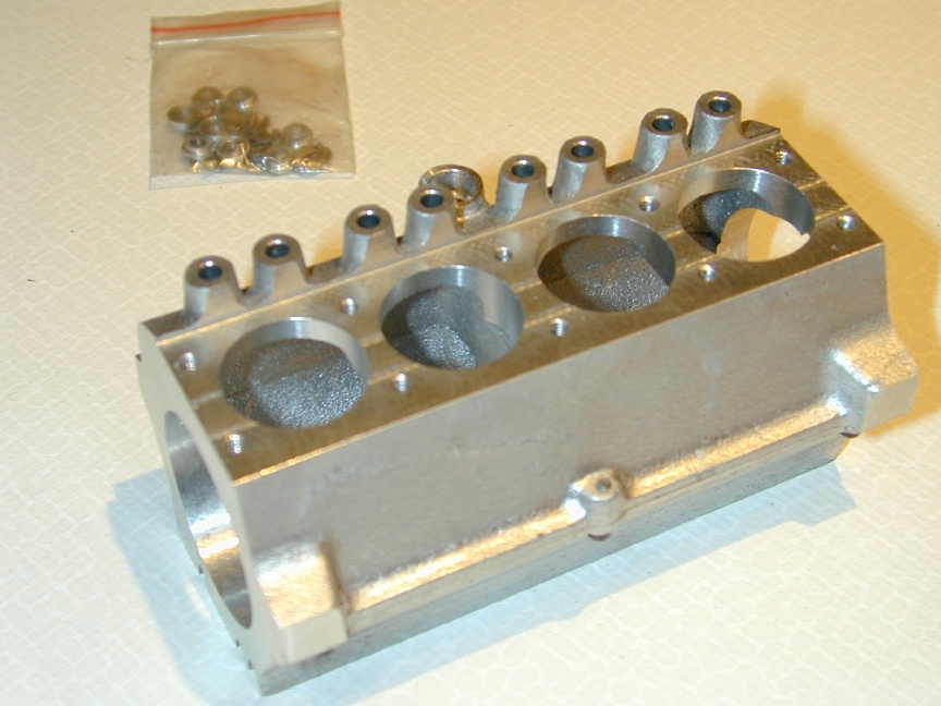 Photo 1 |
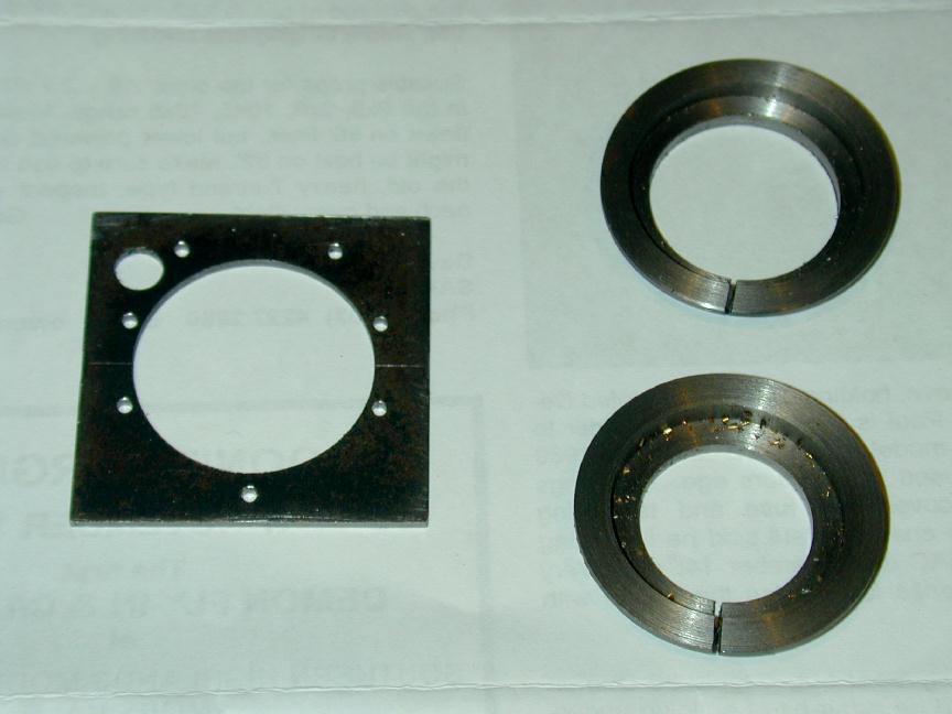 Photo 2 |
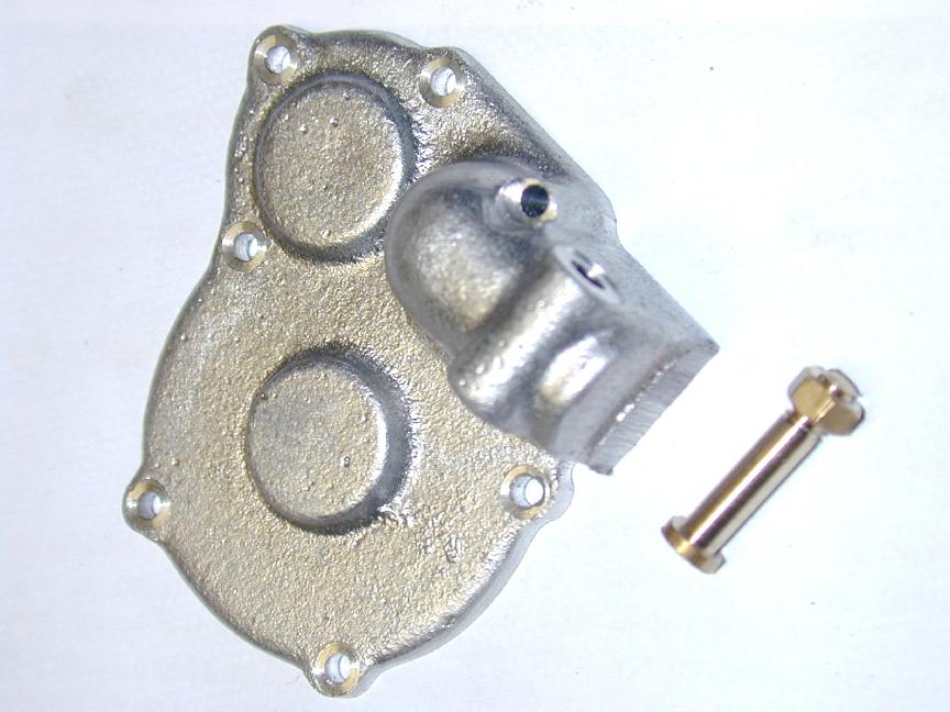 Photo 3 |
 Photo 4 |
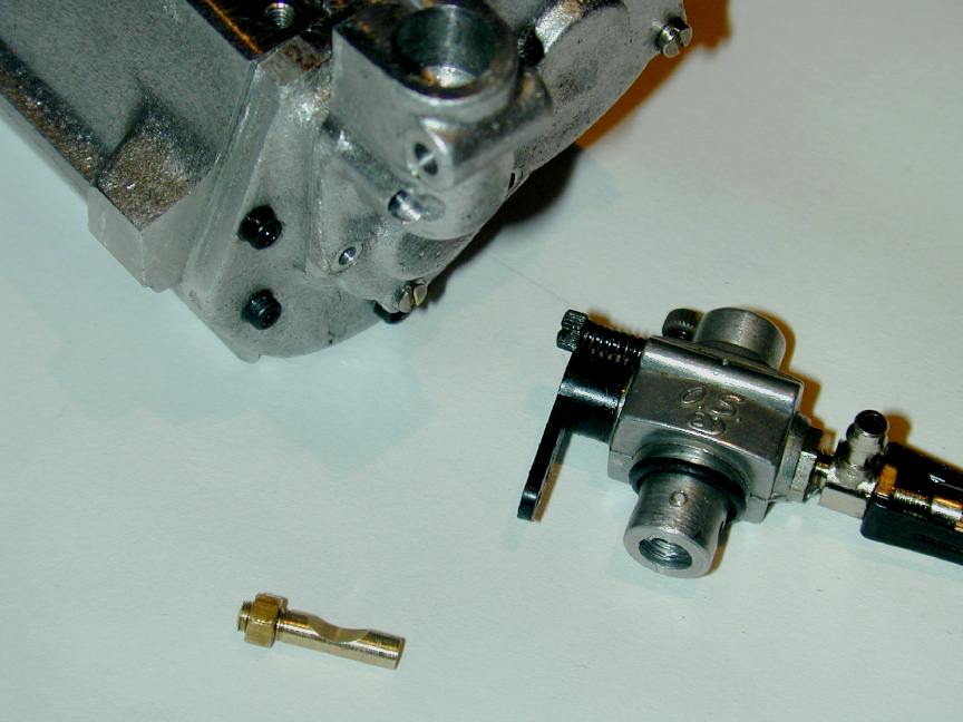 Photo 5 |
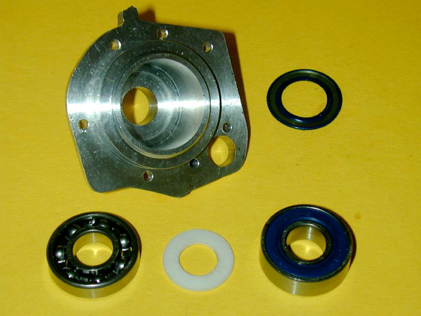 Photo 6 |
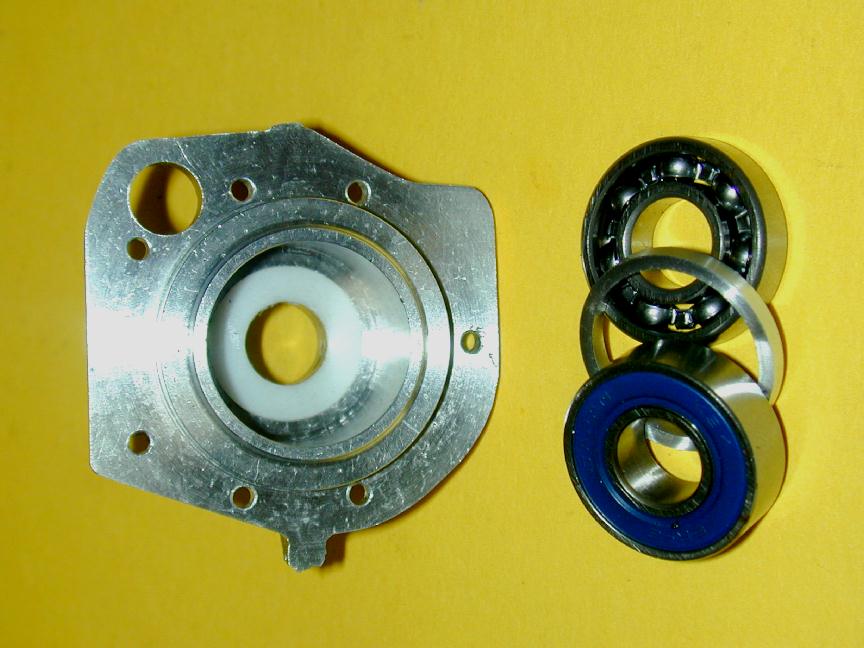 Photo 7 |
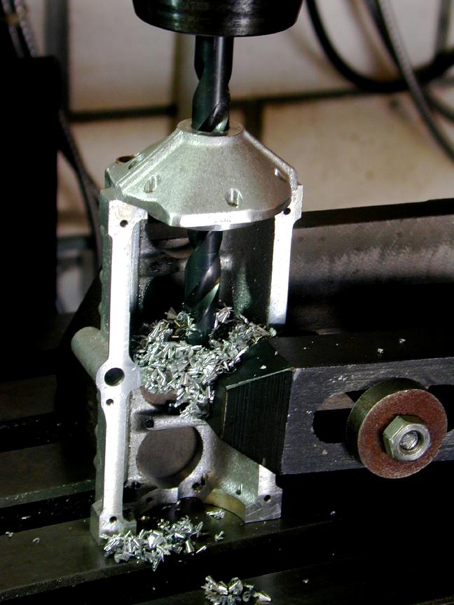 Photo 8 |
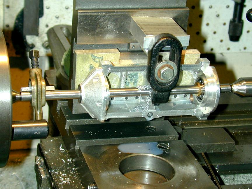 Photo 9 |
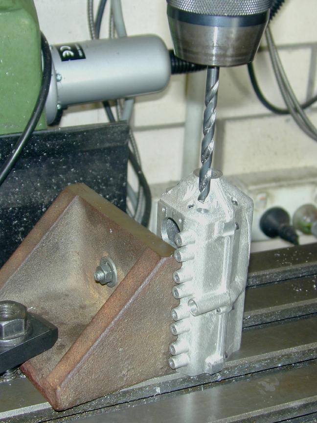 Photo 10 |
 Photo 11 |
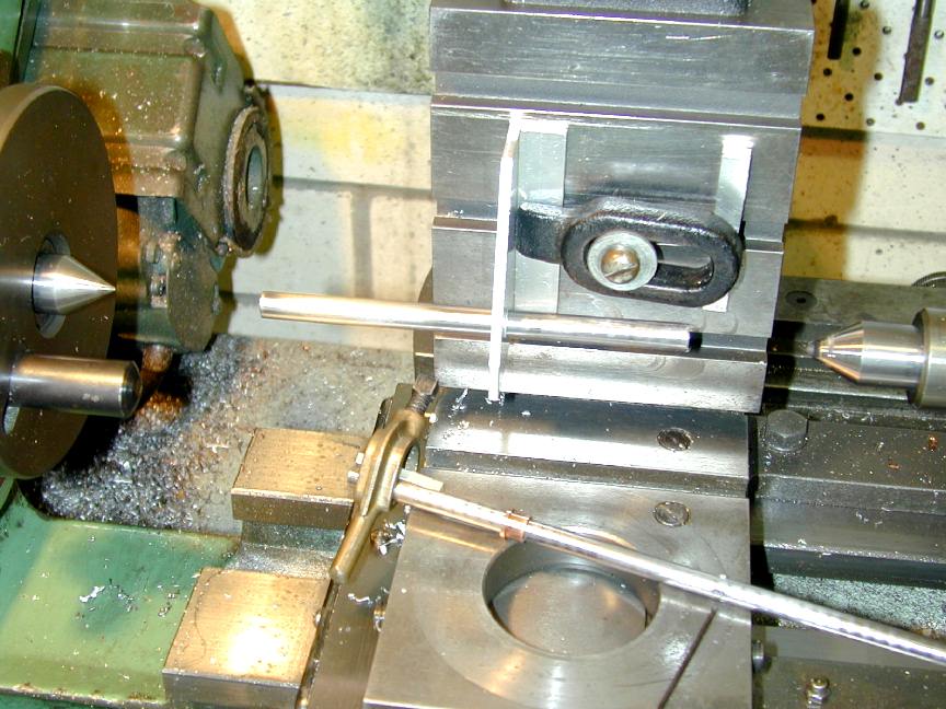 Photo 12 |
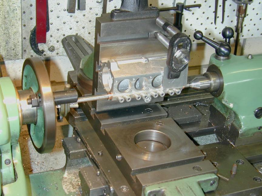 Photo 13 |
 Photo 14 |
Photos 7 and 8 show the front cover, bearings, spacer ring, and crankshaft seal (PTFE). The front bearing is of the sealed type, but with one seal removed from what will be the inner side. The next series of shots show the setups and operations required to line-bore the center support for the cam and crankshafts. The mystery part in Photo #12 is just a piece of scrap aluminium angle used to adjust the boring bar bit (foreground) to the precise size required for the camshaft—as shown by a length of 5/16" drill rod supported in the test piece. The test piece was re-used during cam cutting to provide extra support (see Photos #3 and 4 of the Cirrus Camshaft Page).


This page designed to look best when using anything but IE!
Please submit all questions and comments to
[email protected]
Copyright (c) Ronald A Chernich, 2004-2005. All rights reserved worldwide.