Weaver Construction Log Page 6.
![]()
Piston and Contra-Piston (January - March 2000)
One problem facing small IC engine designers is what to do with the wrist (or gudgeon) pin? It can either float, or be secured. Generally, it's best if floating wrist pins have end pads of some material that's softer than the cylinder walls, although I know of commercial products that simply let the pin scratch the walls as much as they like. Larger engines can use small circlips, or other strange devices to lock the pin into the piston (or the rod). Some designers make the pin a press fit into one side of the piston. This can be done farely easily by using a taper reamer and not completely reaming the wrist pin hole, as described in David Owen's "Mate" instructions. The down side is more precise work required, plus the difficulty of dissassembly.
A floating design is ok if there is no chance it can jam in an exhaust, inlet, or transfer port. The Weaver design falls into this latter category: there's all manner of things for a fore-aft pin to foul in. So Mr Weaver chose a complex, but effective solution. The wrist pin is a floating fit in an aluminum inner piston. The outer piston, made from cast iron, now prevents the pin from moving and presents a totally smooth surface as it passes the inlet, transfer and exhaust ports. The inner piston is secured into the outer by a wire circlip and since the majority of forces tend to keep the inner piston forced up into the outer, this clip does not have to carry any heavy loads. The downsides of this design are added complexity of manufacture, some "delicacy" of the necessarily thin outer piston skirt in the region of the circlip groove, and perhaps some weight panilty, although perhaps not.
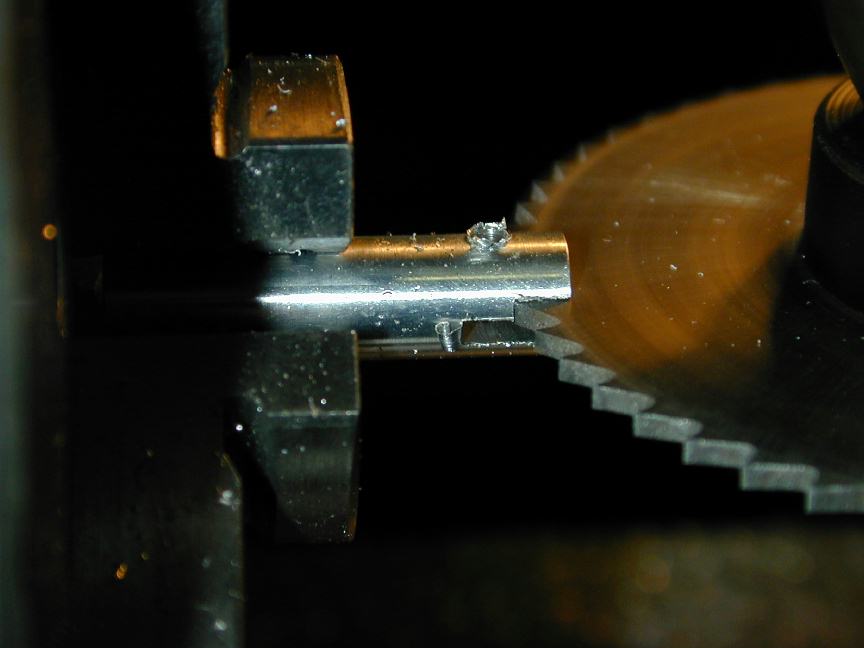
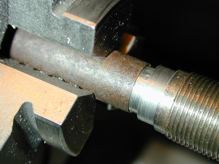
I agonized over the sequence for making the inner pistons for what seemed like weeks. I just could not come up with a sequence that allowed re-use of tool setups. In the end, I just went ahead and made the four inner pistons effectively one at a time. First, a blank long onough for two inner pistons was turned from 6061-T6 aluminum. This was transferred to the rotary table on the mill in the 3-jaw chuck for drilling and reaming of the wrist pin hole. After reaming, the drill chuck was replaced with a .060" slitting saw positioned so the lower face was just below the center of the material. A cut was then made and the part rotated 180 degrees and a second cut made. This produces a slot equally displaced about the center line. The photo shows the second cut for the conrod slot being sawn. This produces an undersize slot, so its width was measured to find out how much more had to be removed. The saw was raised by half the amount and the process repeated. This sequence was repeated for the other end of the blank, plus a second blank!
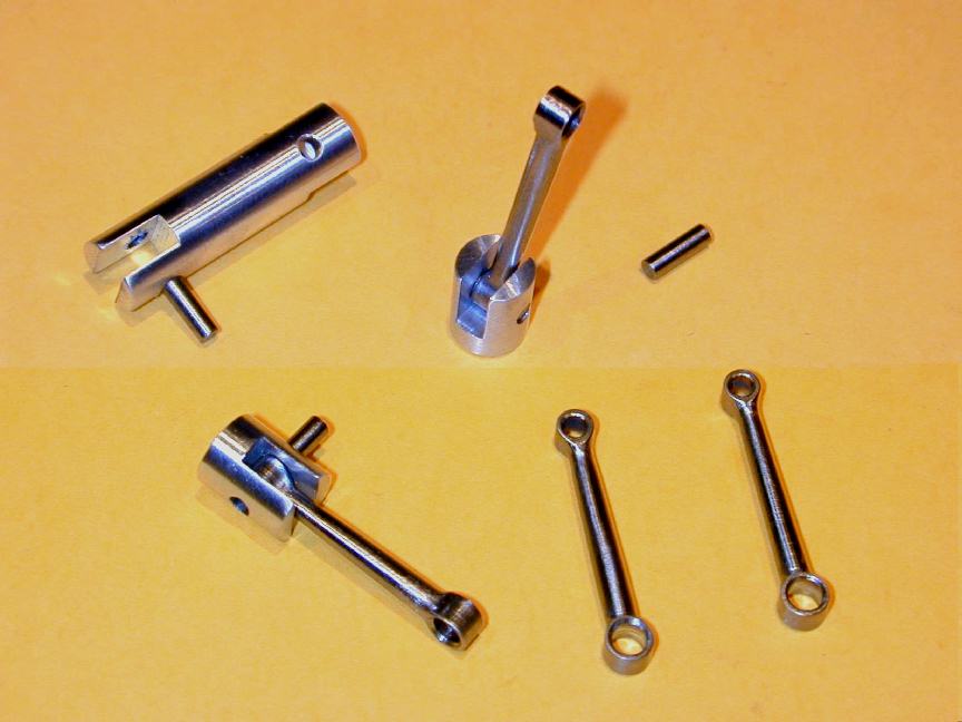
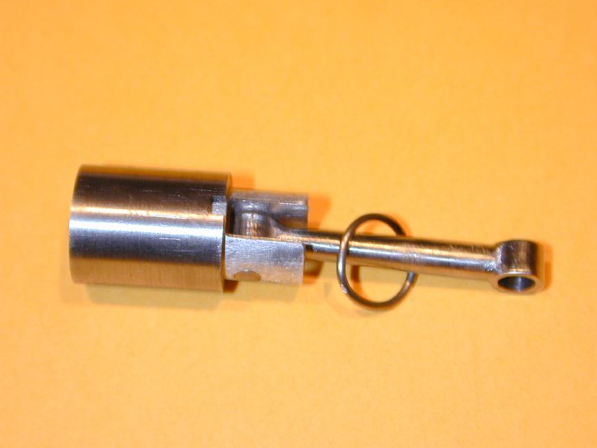
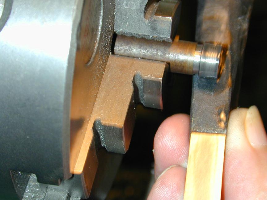
Next, the blanks were sawn in two and the top faced down to give the correct (0.406") height. I should mention that centering of the 3-jaw under the mill spindle only had to be done once, although the exposed face of the blank had to be found each time with an edge finder to locate the wrist pin hole from the base of the inner piston. The wrist pin is sawn from 3/32" diameter water hardening drill rod (using a Dremel cut-off wheel) and faced to length in a collet chuck. This photo shows completed inner pistons, with rods fitted, alongside the blank for the second pair of inner pistons.
The only other difficulty I experienced was when the inner pistons, complete with slot went back in the 3-jaw for facing to length and chamfering. The small size, together with the slot makes it difficult to get the part to run true and hence, achieve a top that's normal to the sides and a chamfer that's concentric. But I persevered, setting up each one multiple times until it was close enough. After it was all over, I realized I have a collet that would have held each one perfectly for this operation. Dumb, dumb Ron. *grrrr*.
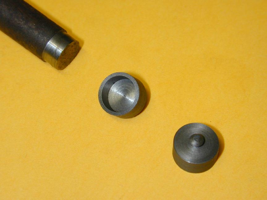
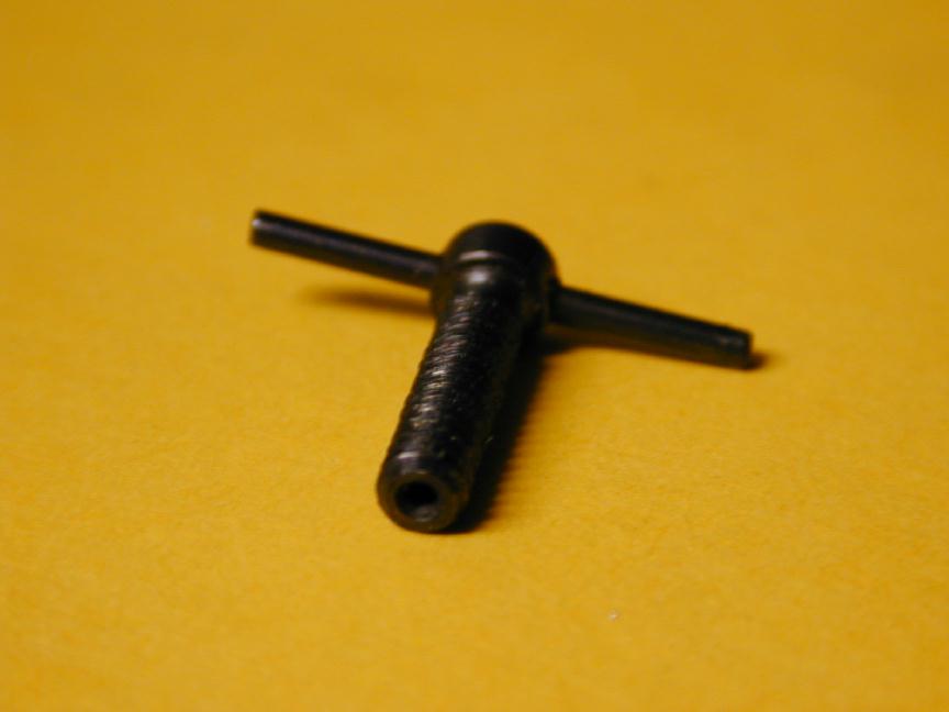
The outer piston of the Weaver is a thin, cast iron sleeve that slips over the inner assembly. The pistons must be finished accurately to the cylinder bore, so now is a good time to complete the cylinder by lapping said bore to a fine finish. The bore needs to be perfectly circular, with a light taper of about one thou or so, narrower at the top. This is a simple task, though a bit messy. To perform it, we need to make a custom lap, as seen in this picture. Laps can be made from aluminum - or brass, copper, cast iron - any material softer than the cylinder itself. I favour aluminum because it's cheaper than the alternates.
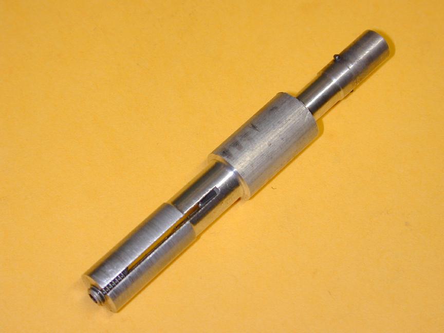
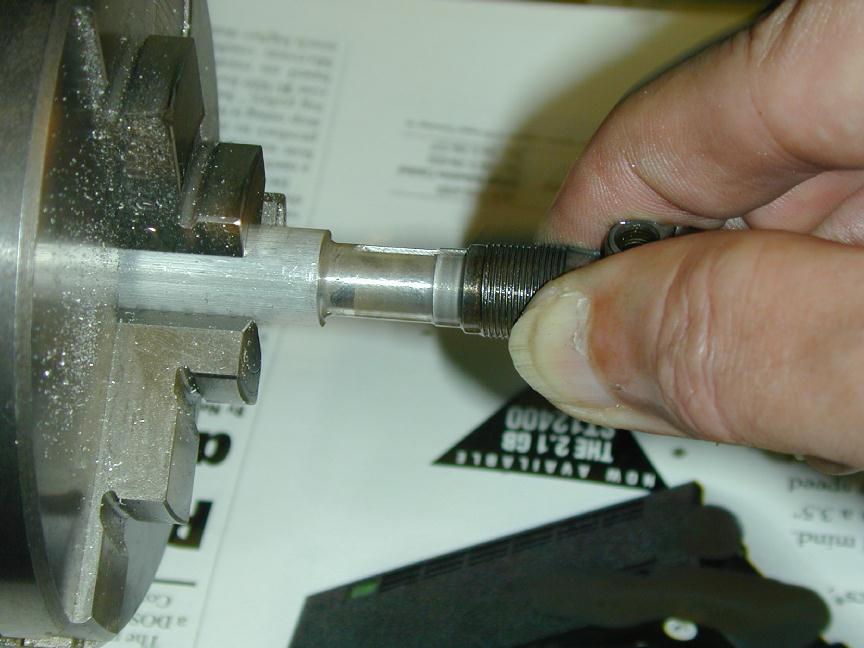
There are a lot of ways to make laps. Essentially, they all comprise a cylindrical cutting surface with some means to expand the diameter. The style I chose here comes from David Owen's "Mate" drawings. It consists of a chucking stub and necked down section smaller than the bore, followed by a section turned to be a sliding fit inside the rough bore of length between 50 to 75 percent of the total bore length. The lap is drilled and tapped with a taper tap to take an Allen head grub screw - 2BA in this case. After this operation, it is slit across the diameter with a 1/16" slitting saw (or hacksaw) so the grub screw will force the lap segments apart as it enters the tapered part of the thread. This shot shows the finished (and used) lap. The reverse end has been fashioned into a special mandrel to hold the outer piston for honing, but more of that anon...
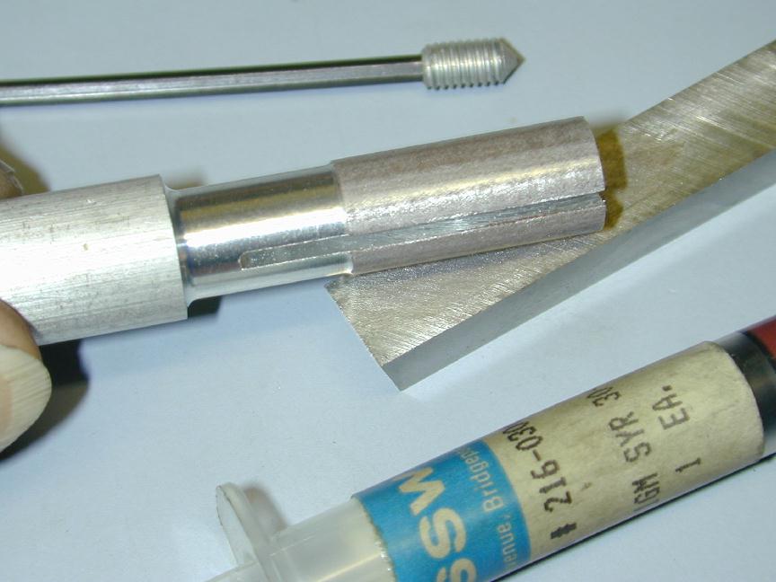
The lap is made into a cutting tool by imbedding an abrasive in its surface. This process is referred to as "charging the lap". I use a diamond lapping paste for this. The "grit" size is color coded and I've found the Red grade works well for our purposes. A feint smear is squeezed onto the lap, them rubbed in against a piece of tool steel as seen in the photo. That's all there is to it - no mystery.
The lap is spun at the slowest (non back geared) speed while the cylinder is slowly stroked over its length, with generous amounts of a light oil as a lubricant. The oil also serves to carry off the cut metal particles, so be very generous with the oil. This picture shows the lapping operation. The lap style chosen is obviously not a "parallel" lap - it will assume a cone shape when expanded, but that is ok since we actually want our cylinder to be narrower at the top so the piston seals well about TDC (Top Dead Center) even when the cylinder is hot - and hence, expanded from its cool diameter. All we have to do is make sure the cylinder is placed on the lap with its bottom facing the tailstock, as seen in this picture. To prevent "bell-mouthing" the ends, just make sure not to expose more that say 40 percent of the lap length when stroking to either end.
This photo shows the bore after lapping and cleaning. The bore shows a fine cross-hatched pattern which will retain oil when running. Cleaning is important as any left over cutting particles will quickly wear out the piston. I use an ultrasonic bath, but sloshing in kerosene, or even soapy water will work just as well. Be sure to give the cylinder a good spray with WD40, or something similar after drying off.
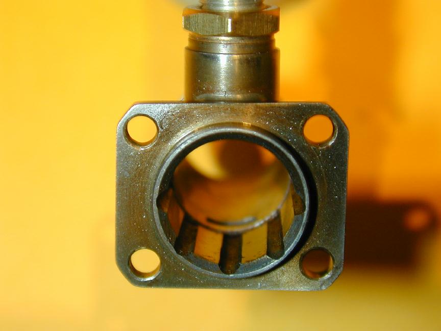
Now we can make and hone the outer piston to fit the cylinder bore. First the blind hole that will accept the inner piston is drilled and bored. When the engine is running, compression and ignition will keep the two together quite well, but to keep them together at other times requires a little clip. This is just a circlet of 1/32" diameter music wire, so we cut a 0.032" wide channel, 0.016" deep with one edge level with the bottom of the inner piston as seen in this shot. The outer piston is then turned parallel to about one to one and a half thousandths of an inch greater in diameter than the cylinder bore at the TDC point. Finally, a 1/16" slot is cut across the piston diameter. This slot aids removal of the clip and also engages driving pins while the piston is being honed. Finally, the piston is parted off and faced to correct total height.
We need another fixture to hold and drive the piston during honing. The piston is thin walled cast iron and so is easily distorted. The fixture is made a close sliding fit inside the piston, thus providing support against pressure. It is cross drilled to carry a driving pin. I made it from 0.055" diameter music wire, smaller in diameter than the finished piston, but large enough to engage the slot in the piston base. As seen in this shot, the piston is slid over the mandrel and retained by bringing up a length of brass in the tailstock to lightly touch the piston crown. The brass should be smaller in diameter than the piston so the external hone can easily stroke over the piston length as seen in this photo.
The hone is lightly tightened on the piston, the lathe run in slowest non back-geared speed and generous oil applied to the cutting stone. Progressing slowly, the piston is brought to a fine finish and size so that it jams in the bore at the point where the inlet port is just uncovering. With a little running-in, this will produce excellent running compression that will last for several seasons of sport flying. This photo shows the finished piston assembly with retaining clip.
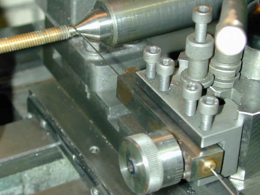
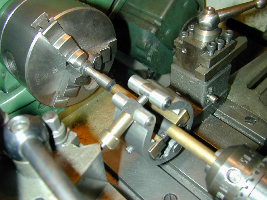
The clip was formed around a mandrel smaller in diameter than the required ID by twice the wire thickness, to allow for spring-back. This shot shows my setup for making springs and such things. The mandrel has been turned on the end of a convenient brass bolt, which was then cross-drilled to form an anchor for the wire while forming the coil. The gadget in the tool post places an adjustable amount of drag on the wire. It is "calibrated" so similar results can be achieved over several springs. The design appeared in SIC quite some time back. It is a usefull gadget.
Nearly done now - only the contra piston remains. This part is also made from cast iron and must be finished to be a tight push fit in the top of the cylinder. It should move easily as the compression screw is turned, yet not leak. It should also "snap" up when the screw is backed off and the engine turned over. It's not uncommon for me to make a couple of these for each engine before achieving the right fit. Well, no more! That David Owen fella is one smart cookie! Here is the DCO method for sure-fire, no-drama, super-easy, hone-free, completely painless contra piston fitting.
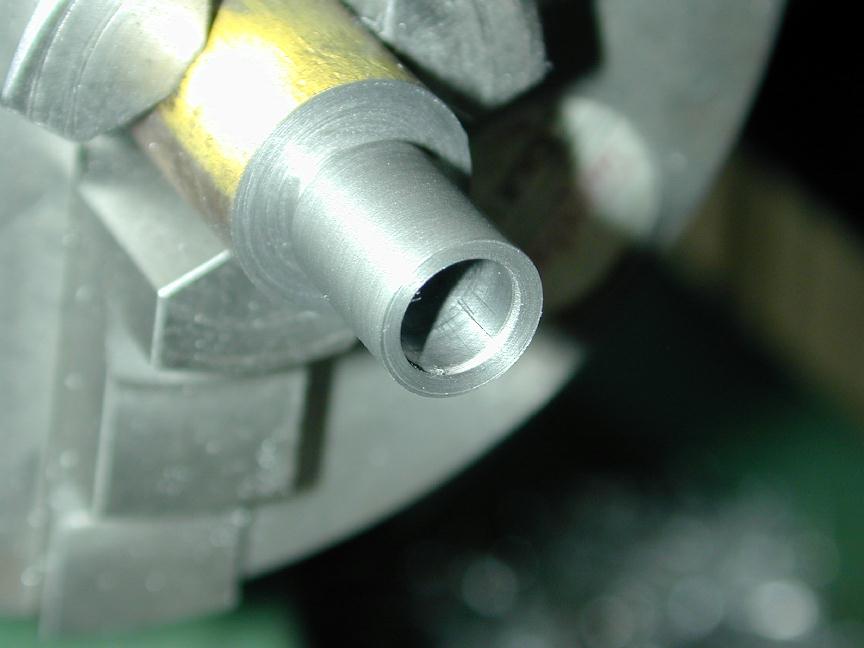
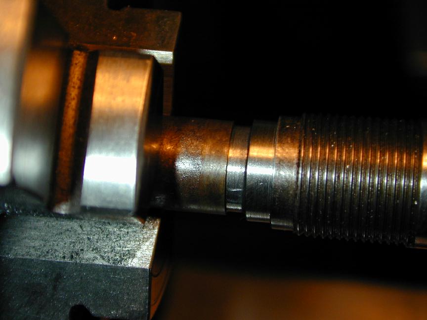
To start with, the contra piston is bored to have a flat bottom and an ID that will result in thin walls of about 1/32" thickness (between 0.03 to 0.04"). The outer diameter is turned to be about 15 thou greater than the top of the cylinder bore. The part is then parted off to length as seen in the previous photo.
Next, it is mounted on a suitable mandrel (from brass, steel, plastic, or wood even!) and fixed with a drop of Loktite or cyno (instant glue). We now set over the top slide by a shade less than one half of one degree so the final diameter will be tapered, narrower at the bottom, wider at the top (included angle less than one degree). The diameter is reduced until the contra piston end will just enter the top of the cylinder bore to about the thickness of the crown. The 15 thou allowence compensates for any loss of concentricity between this setup and the previous one.
Now with a piece of fine wet and dry glass paper (I used 800 grit), backed up by a piece of flat, ground tool steel and given a good drop of oil, the surface is brought to a fine finish. At this point, the piston will enter the bore for perhaps one quarter of its length before jamming. The part is now separated from the mandrel with a drilled bar, or released by heating in a gas flame. It can now be thoroughly cleaned and pressed into the cylinder top. The thin walls compress giving a perfect, gas tight seal which moves readily.
The old way involved walls thick enough to tap for the finishing mandrel. The piston was then honed (with a danger of making it barrel shaped due to its short length). All in all, a rather hit and miss process. Now, if the final fit is too tight, it would be a simple matter to place it back on the mandrel and give it another rub with the glass paper. Nothing could be simpler. David, your blood's worth botteling, mate! After doing this once, I can't imagine fitting contra pistons any other way.
Now a final tip from David. Hollow out your compression screws. This can be as simple as a small center drill for something Weaver sized. The idea is to prevent point contact between the screw tip and the inside face of the contra piston as this will tend to promote compression drift under vibration. Also, tap the screw hole first, then open out the die when cutting the male thread so the screw is a close fit in the thread. Do this and no form of compression lock will be needed. Incidentally, the black finish seen here was done by placing the component in a gas flame until it had "blued" to a deep blue/black, then quenching in water. Not perfect, but not bad either.
Back to Weaver Journal front page 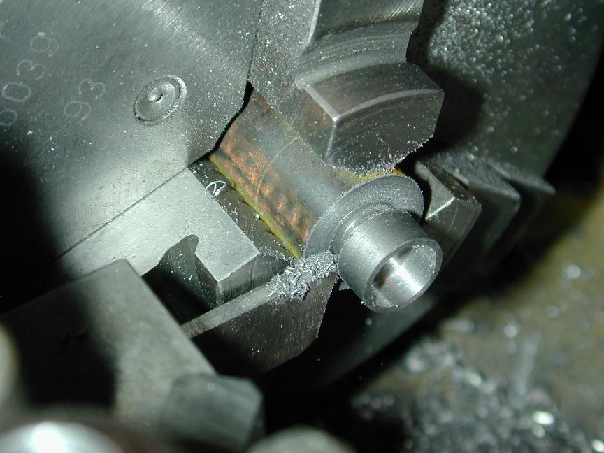
![]()