Weaver Construction Log Page 4.
![]()
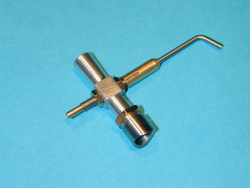
Venturi and Needle Valve Assembly (October 1999)
 In the previous section, the cylinder had progressed to a nearly finished state, still requiring internal lapping. Lapping should always be the last operation on a cylinder of this type. This means the boss for attaching the side port venturi must be fitted before lapping can be done. In this session, I decided to make the boss and the associated parts for the venturi and needle valve.
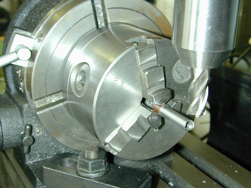
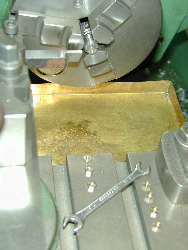
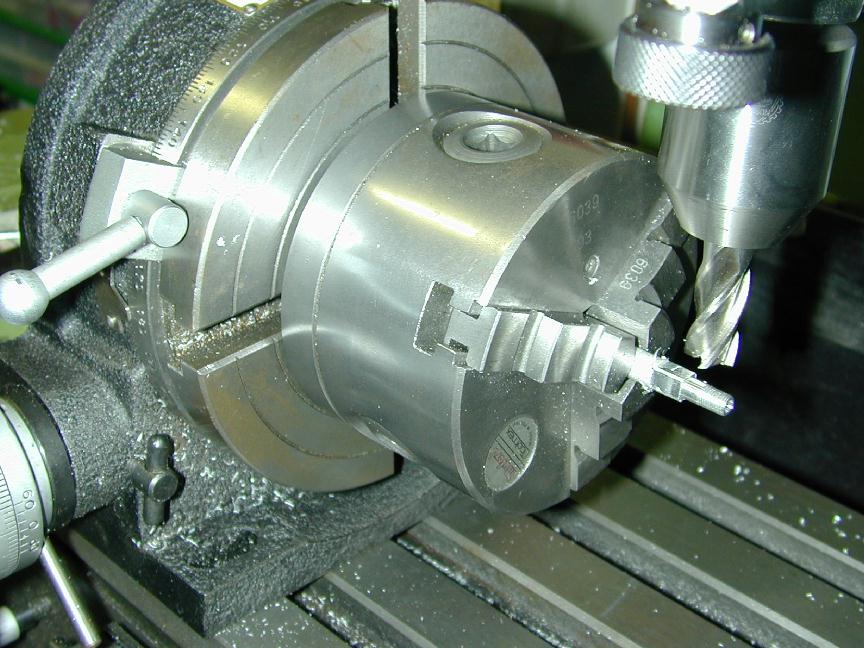
The boss will be soft soldered to the cylinder (diesels don't get hot enough to melt soft solder). One of my old electronics instructors at DCA used to say "solder does not make the joint, it only keeps the air out" and schooled me to make a good fit of parts to be soldered. The boss will butt to the cylinder which has an outside diameter of 0.500". So, a good fit can be achieved by profiling the boss with a 1/2" end mill. In this photo, we see the boss blank (enough for four) which has been finished outside, drilled ready for tapping and transferred still in the 3 jaw chuck to the mill for end profiling. In the past, I've also carried out this operation with the end mill in the headstock and the work held in the tool post (see the needle valve slitting operation photo, below).
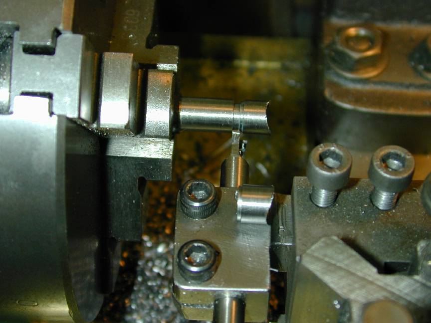
With the chuck back on the lathe, the boss can be parted off. This is done by touching the tool side to the end of the profiled boss, then advancing the tool by the boss length plus the tool width using the compound slide. A first cut is made to 0.020" deep, 1/32" short of the part-off point to form the reduced diameter seat for the venturi locking nut. It's a toss up on when to tap the boss. If it's done first, we'll have to run the tap thru again to clean the burr created by parting and drilling the 1/4" recess. If we do it after, the part will be blemished by the jaws of the chuck gripping on its OD while tapping. Since I've had to order the 7/32" 40 TPI tap (thought I had one!), the choice is made for me - tap later. You can see a finished (sans tapping) boss sitting on the tool holder in this shot.
Knowing that many of my projects stall on little, nigglely jobs, I decided to roll right on with all the needle valve assembly (NVA) bits. In the best British tradition, these are called out as a 6BA thread, though 4-40 would be close enough were I not blessed with a good supply of BA hardware. Each NVA requires two nuts, thinned down to 1/16" thick. The easy way to do this is mount a little mandrel with a 6BA stub and position a part-off tool in relation to this mandrel to do the thinning. The nuts are screwed on to the stub and turned to length, then re-beveled as shown above.
 In the photo, a little split chuck with an internal 6BA thread is gripped in the 3 jaw chuck. A 6BA screw has been threaded into this from the headstock side to allow just enough threads to protrude to carry the nut. When the chuck is tightened, the little split chuck grips the screw tightly. This split chuck can also be used to hold screws very tightly without marring the thread. Very usefull, though not 100% with regard to run-out.
With all the nuts thinned, the upper and lower spray bar parts can be made. Although we could make these from brass stock, it's simpler to modify 6BA brass screws for the job which merely requires drilling a 1/16" hole up the middle - all the way for the upper and part way for the lower, finishing the job with a #60 drill to form a needle valve seat.
In the photo, a little split chuck with an internal 6BA thread is gripped in the 3 jaw chuck. A 6BA screw has been threaded into this from the headstock side to allow just enough threads to protrude to carry the nut. When the chuck is tightened, the little split chuck grips the screw tightly. This split chuck can also be used to hold screws very tightly without marring the thread. Very usefull, though not 100% with regard to run-out.
With all the nuts thinned, the upper and lower spray bar parts can be made. Although we could make these from brass stock, it's simpler to modify 6BA brass screws for the job which merely requires drilling a 1/16" hole up the middle - all the way for the upper and part way for the lower, finishing the job with a #60 drill to form a needle valve seat.
 The lower spray bar half also gets the threads turned away where the fuel tube will be slipped on (I assume the designer felt putting tube over the thread would invite air leaks - this is pure assumption on my part, but it seems logical as Ms Spock might say).
While this photo shows the screw being held in the split chuck for drilling and turning, I was not happy with the concentricity achieved this way, so I started again, gripping the screws in a collet. This gave perfect results, with minimal to no marking of the thread.
The lower spray bar half also gets the threads turned away where the fuel tube will be slipped on (I assume the designer felt putting tube over the thread would invite air leaks - this is pure assumption on my part, but it seems logical as Ms Spock might say).
While this photo shows the screw being held in the split chuck for drilling and turning, I was not happy with the concentricity achieved this way, so I started again, gripping the screws in a collet. This gave perfect results, with minimal to no marking of the thread.
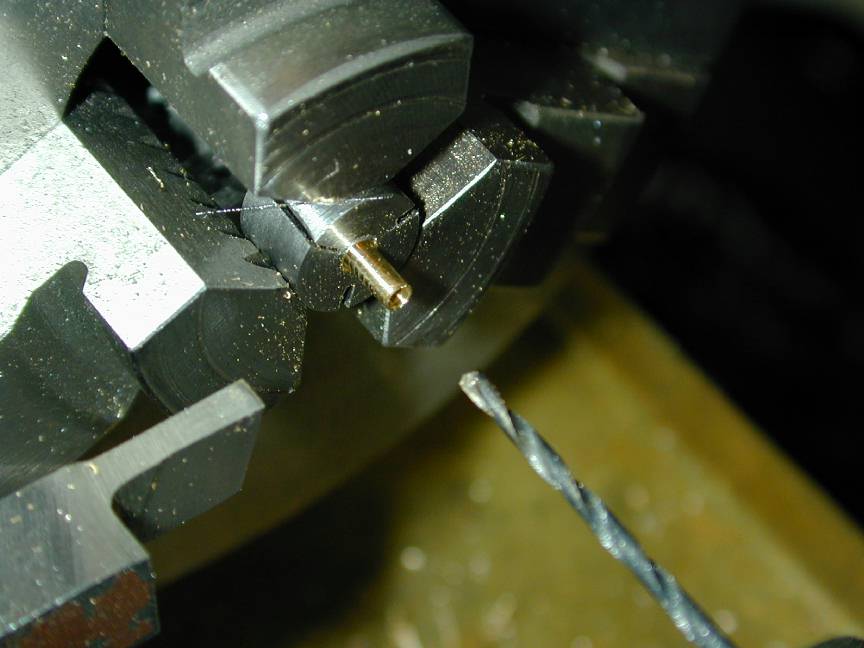
The needle valve thimble is made from 5/32" diameter brass stock (the K&S bars at your local hobby store are a good, ready source of supply for this, although rather expensive). It is drilled #42, 3/8" deep for tapping 6BA, then drilled thru 1/16" for the needle. This is best done at the same setup to ensure maximum concentricity. Again, I've used a collet to grip the stock in this photo. The tap is positioned using a drill chuck in the tailstock and gets a drop of Devcon TapMagic (or some such name) on it. Probably does about as much good as waving a bone over the job, but who knows?.
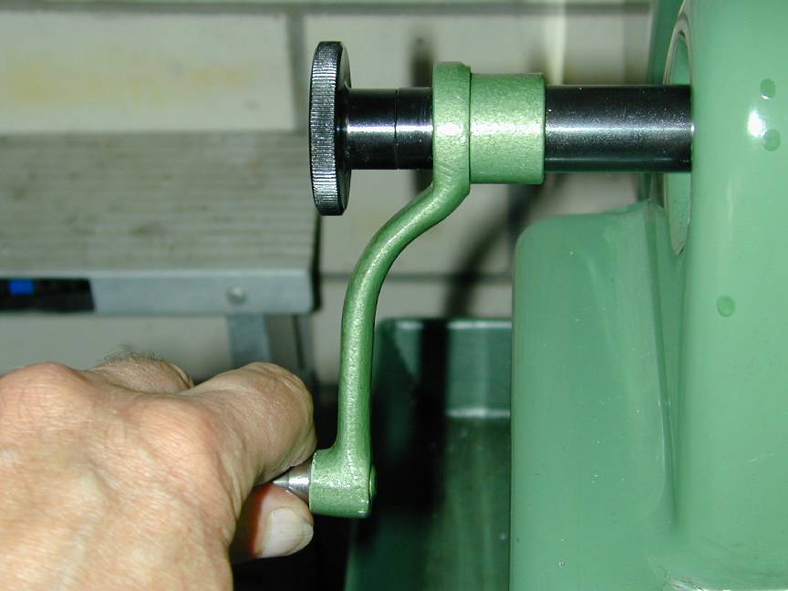
The work is rotated by hand using a handle that grips the inside of the Myford headstock spindle. As this approach provides no tactile feedback to warn of iminent tap breakage, work slowly, backing off the tap frequently, listening for that tell-tail screech brass gives when a tap is binding and watching torsional forces on the tap itself. You can see the tap start to twist before it breaks. At this point, score NVA thimbles five and taps nill for a job well done.
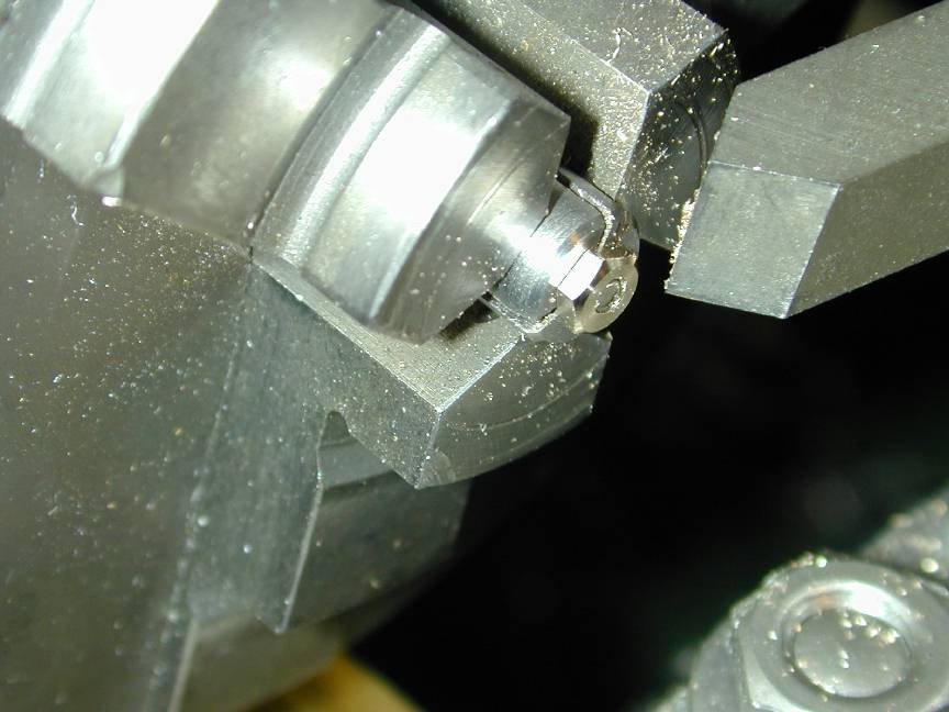
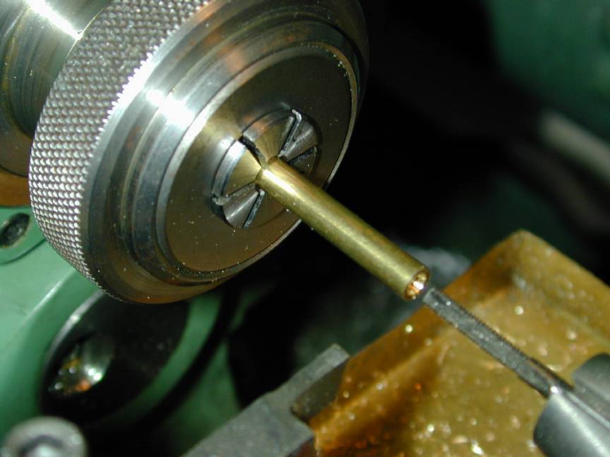
The final tasks for the thimbles are to slit them for about 0.2" from the threaded side and to part-off and put a decorative champher on the operator side of the piece. The slit allows the thimble thread to be closed down to a comfortably tight friction fit on the spray bar. Done correctly and adjusted carefully, this works well. The easiest way I've found to do this is to use one of those handy little Dremel part-off, abrasive disks, mounted on its Dremel mandral, but gripped in the lathe chuck.
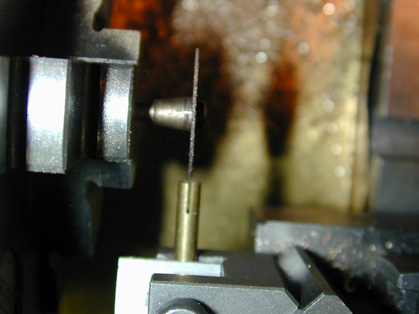
The brass stock with the partially complete thimble is mounted in a lathe tool holder and adjusted to centre height. The cut-off disks are about 0.024" thick. Touch the stock to the disk, then using the compound slide, advance towards the headstock by the material diameter, plus the disk thickness, divided by two. Run the disk at high spindle speed and advance the threaded thimble into the disk with the cross slide to to required depth. The cut is so clean, you won't even have to run a tap up the thread to clean out burrs. Take care to adjust the stock to the same plane as the disk and advance the cut slowly. Even a little off line will be noticible in the end result (like on this one).
 The venturi poses no real problems. In this photo, the side that screws into the cylinder boss has been turned and threaded 7/32"x40 TPI using a "ME" (Model Engineer) series die, then drilled thru #36 and the exit side tapered using a 000 size taper pin reamer. After all blanks reached this stage, it's over to the mill where the middle 1/4" of the blank is squared using an end mill. Calculate the amount of stock to remove from each face so the center will be 1/4" across the flats. As I was using 5/16" stock, the amount was 0.031" and the corners still reflect the stock OD. No problem - even looks cleaner.
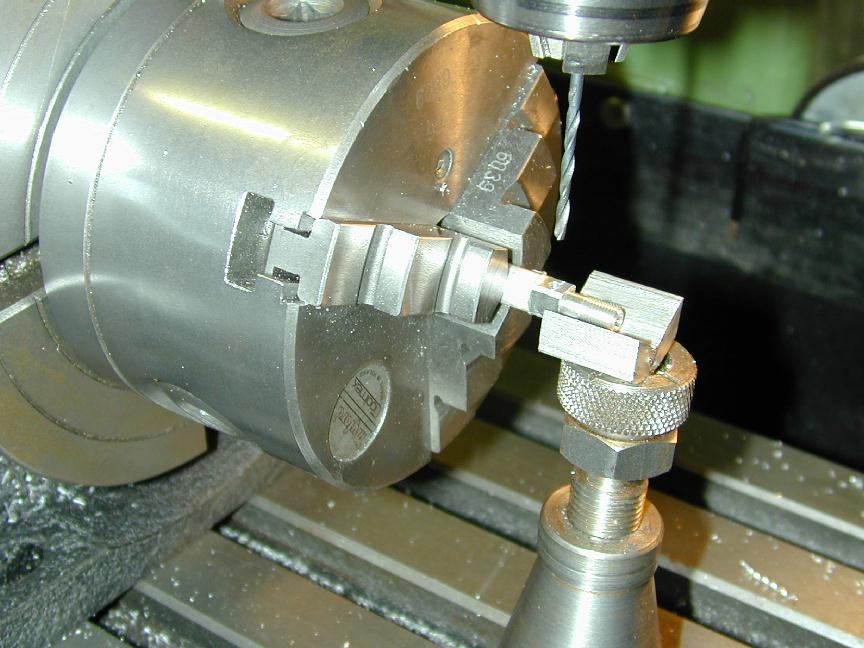 Following milling, each venturi is cross drilled and tapped 6BA for the spray bar components. Again, I'm using a little bottle jack to support the part so drilling forces don't deflect the stub causing the hole to be at an angle to the normal. After this operation, the chuck goes back to the lathe and the inlet side is taper turned at three degrees and reamed with the 000 reamer. If this is done correctly, the portion around the cross drilling will still be the original #36 diameter. Finally, the very end is drilled with a #3 center drill to give a 60 degree taper for a short distance.
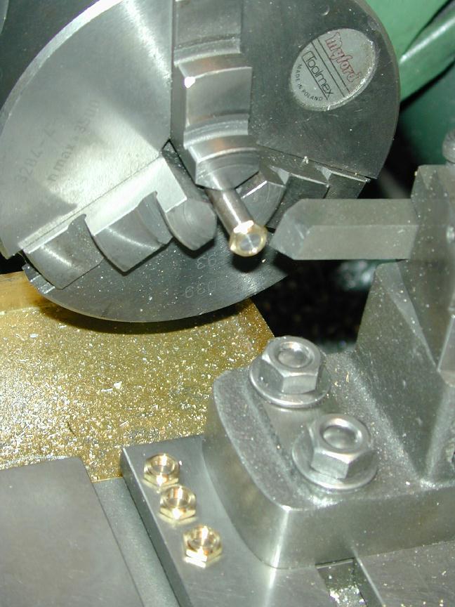 Here the lock nuts that secure the venturi against the cylinder boss are being finished on a short threaded mandrel. The end of a piece of brass hex rod has been drilled and threaded, then the blanks parted off. The side that will face against the boss is finished before parting to ensure it is perpendicular to the nut axis. Screwing onto the mandrel allows the far side of the nut to be faced and the edges of the hex to be chamfered 30 degrees giving a nice, rounded appearence. The mandrel will also be used when soldering the boses to the cylinders.
To complete the assemblies we just need the needle itself. The original Weaver plans call for a gramaphone needle. Well, I barely remember such things, and I'm getting distinctly ancient, so the original source is out of the question, except in the CSR, perhaps? Generally, I make needles out of 1/16" dia "piano wire". The needle is ground off-hand by spinning a length of wire, the longer the better, against the side of a grinding wheel to rough the shape. Next, repeat against a disk sander (other end of my bench grinder) and finally, buffed and polished against a Scotch-Brite (tm) belt - also on the bench grinder.
 The needle thimbles were drilled #53 (0.059"), but drills always cut oversize, so the resulting hole is a tight press fit on 0.063" dia wire. At the left of the photo is a little pressing gizmo which has been drilled thru #50 to clear the wire and counterbored 5/32" dia with an slot drill. I grip the wire, pointy side up, in the bench vice soft jaws, then drop on the ferrule, split side up. The gizmo drops over this and gets enough blows with a light hammer to force the ferrule down the needle. The length of the gizmo is such that the pointy bit is never in danger of being hammered. Simple. Agricultural. Effective.
 Finally for this chapter, we soft solder the venturi bosses to the un-lapped cylinders. Soldering is easy if the parts are very clean, so first they get a good rub with 600 wet and dry, used dry. To align the boss, it is screwed to the stub mandrel (mentioned earlier) and clamped to the cylinder over the inlet port. The MkI eyeball is good enought to tell when the stub is aligned at 90 degrees to the mounting flange (the eye/brain is very good at picking right angles, so better to use it before the solder is applied!). The heat is applied mainly to the stub/boss from a gas tourch with a small brazing tip fitted.
 Diesels don't run hot enought to melt high temperature soft solder. The stuff I've used comes from CIG and has a high silver content, melting at about 700 degrees. CIG also supplies a flux which is either acid or killed spirit based as it promotes instant rust. In this photo we can see how my skill at soldering Weaver bosses improved over time. The cylinder on the left is the third attempt - I think I'd gotten the hang of it by then.
 And here, at the end of November, 1999 (after a three week break to make three EZE's), is progress on the Weavers. Astute readers will notice the field has thinned from four to three. The #1 cylinder was irrepairily stuffed by cutting the transfer belt too low. So, I need to make another cylinder for it and I'm thinking of changing the induction from side-port to rear rotary valve, just for fun. Anyway, three out of four ain't bad?
![]()
Back to Weaver Journal front page