Weaver Construction Log Page 3.
![]()
Cylinder and Cylinder Head
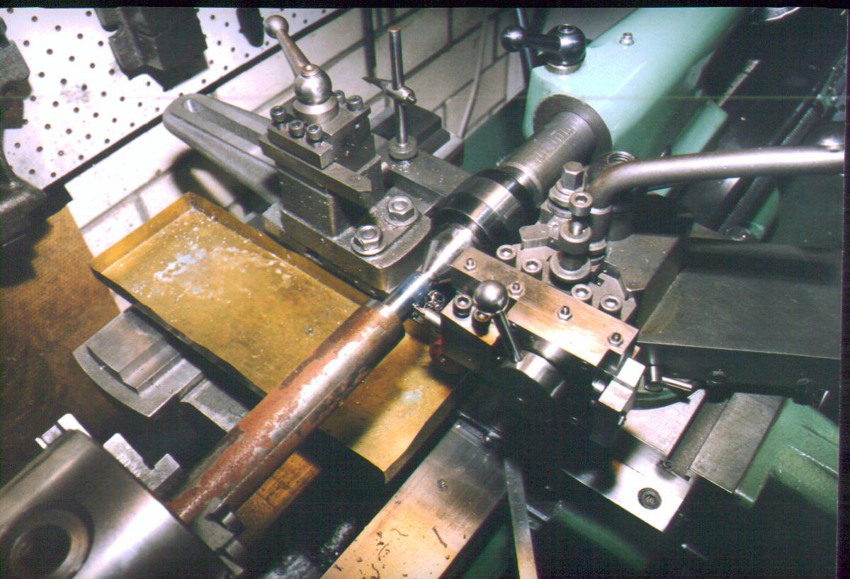
The Weaver cylinder is turned from 7/8" diameter steel bar stock. Russell case hardnes the interior of his. I don't bother. In the first stage, the outline is finish turned, oriented with the mounting flange towards the headstock. This permits the thread for the cylinder head to be cut at the same setting. Here the GHT retracting tool holder is being used to cut the thread (follow the link from my Links Page to Hemmingways who produce a kit of materials and plans for this tool).
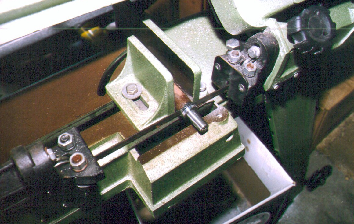
Here I'm being cheap, sawing off the partially finished blank to save metal (actually, it's easier than parting off). Just need to be ready to catch the part before it falls to the floor and damages the thread! It's very important that the cylinder bore be perfectly normal to the mounting flange. The sequence here ensures that the flange is finished at the same setup as the bore is drilled and reamed. That should do it.
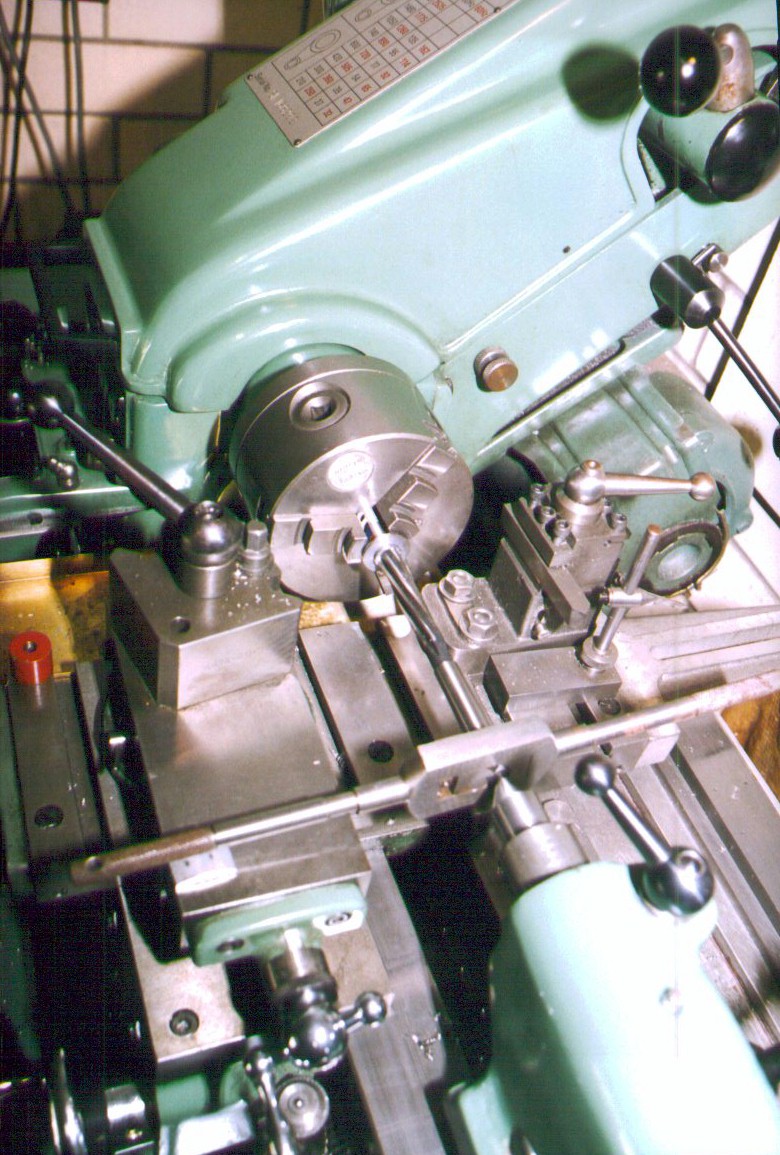
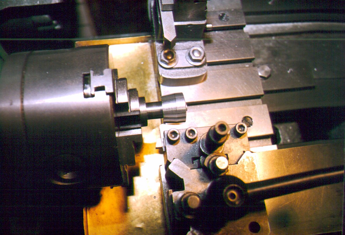
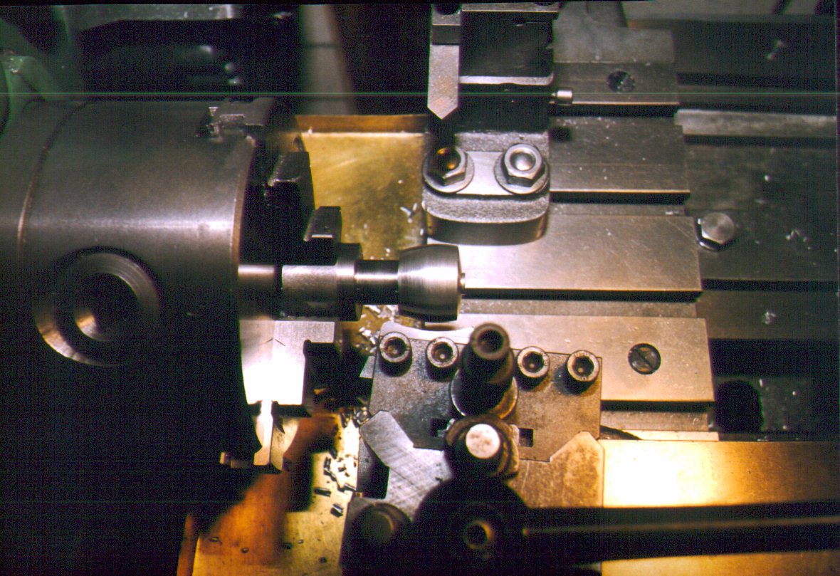
The cylinder blank has now been replaced in the 3 jaw chuck with the top of flange against the jaws and some thin aluminum shim (beer can material) arount the outside to protect the finish and thread. The bore will be drilled so as to leave 8 to 10 thou to be removed by the reamer. It is pilot drilled first. I'm told it's good practice to select a pilot size no grater than half the next drilling size to prevent the next size wandering. Here we see the reamer being floated into the bore using the tailstock (larger hand reamers will have a dimple in the end which assists this operation. For this operation, the headstock is turned by hand. Keep up plenty of suds and never rotate the chuck backwards. The reamer is prevented from rotating by resting the tap handle on the compound slide. A piece of shim material protects the slide from damage by the handle.
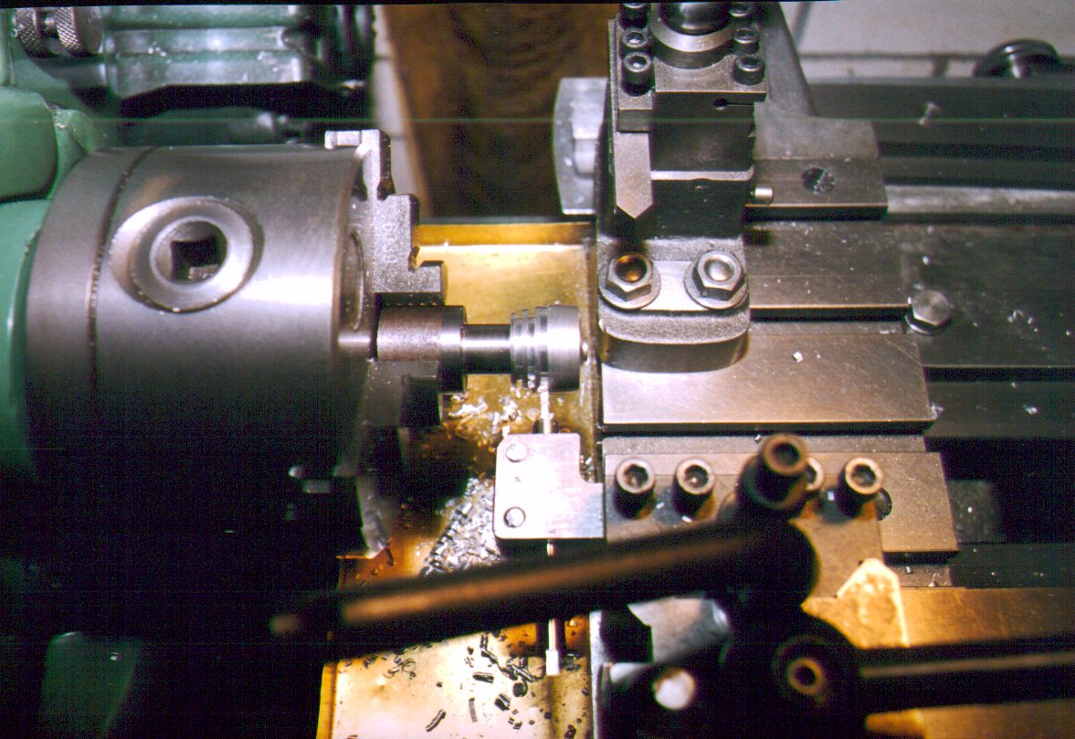
The transfer ports of the weaver are unusual. They comprise 5 vertical channels, spaced equidistantly arount the forward 180 degrees of the cylinder. They terminate in a "transfer belt" (Weaver's terminology) below the exhaust ports. This arrangement avoids the induction port at the cylinder rear. These ports cannot be cut before reaming (or boring) as their presence would make it impossible to cut the bore accurately. This flash-failure shot shows how they are drilled. A short aluminum (or brass) plug is turned to be an interference fit up the bore. The holes are then drilled at the intersection of the cylinder and plug. The cylinder wall will be quite thin adjacent the transfer passages, but by using a slightly softer material for the plug, the drill will incline towards the softer material, preventing any danger or a ruined part.
Not illustrated is the exhaust porting operation. This is carried out with the cylinder in the chuck, sitting vertically on a rotary table on the mill. A .060" slitting saw is advanced into the wall so as to leave adequate support between the three, 120 degree spaced ports. The inlet port is chain drilled (a row of 0.059 holes) and opened out to a 3/16" x 1/16" slot using a burr in a Dremel hand tool. Finally, the "transfer belt" is turned internally using a saw-tooth shaped tool bit in a boring bar. This is arranged with the slope of the tooth slanting upwards to direct the transfer charge up and away from the exhaust ports. A little fiddly, but no great hassle. All that remains is squaring the flange, drilling the mounting holes, soldering on the inlet boss and final lapping of the bore. We'll leave these tasks for later.
Before the last cylinder is finished (remember, I'm making four at once), it is used as a screwed mandrel to hold the cylinder heads for exterior finisherng. In this shot, the interior of the head has been bored and screw cut. The head has then been screwed onto the cylinder (gripped by the yet to be sawed material stub) and a slight taper turned onto the exterior of the blank. The outside will be finished with a form tool made from a piece of gauge plate (high carbon steel) which has had a concave radius cut in it.
The plate was then hardned and tempred and the radius sharpened (Dremel tool again) relieving the edge below the radius. It is mounted in a tool post holder and advanced into the spinning head. Using a speed just short of the "chatter" speed and jiggling in-out, for-aft movement, a smooth profile is quickly achieved. These two shots are effectively before and after shots for the process. One edge if the form tool has a sharp corner. The top of the head was profiled by rotating the tool 90 degrees and profiling the surface facing the tailstock, leaving a little boss which will be drilled and tapped for the compression screw before the part is removed from the mandrel.
Before that operation, the end is center drilled so a live center can be used to support the head as the cooling fins are cut. In this shot, the fins are cut to depth using a parting off blade being advanced "up" the head by an amount carefully calculated from the distance to be traversed so that all fins will be of equal height. The tool used should not have a "V" ground on its top as this shape does not produce a flat at the end of the groove. I'm using a tool made from the ubquitous 1/4" diameter HSS steel, ground on the Quorn and held in a (wait for it) holder designed by George H Thomas, as detailed in Model Engineer of the late 70's and reprinted, posthumously, in a terrific book called "George Thomas' Workshop Manual".
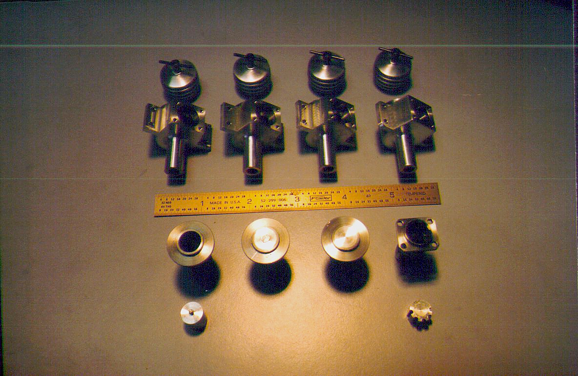
That completes work on these components for now. The badly lit shot showing the porting plug above shows progress to date. The making of the compression screws has not been documented. They are simple turning and threading operatoins, followed by cross drilling for a piano wire tommy bar. Finally they are heat blued for appearence and surface protection.
![]()
Back to Weaver Journal front page