Weaver Construction Log Page 2.
![]()
Backplate

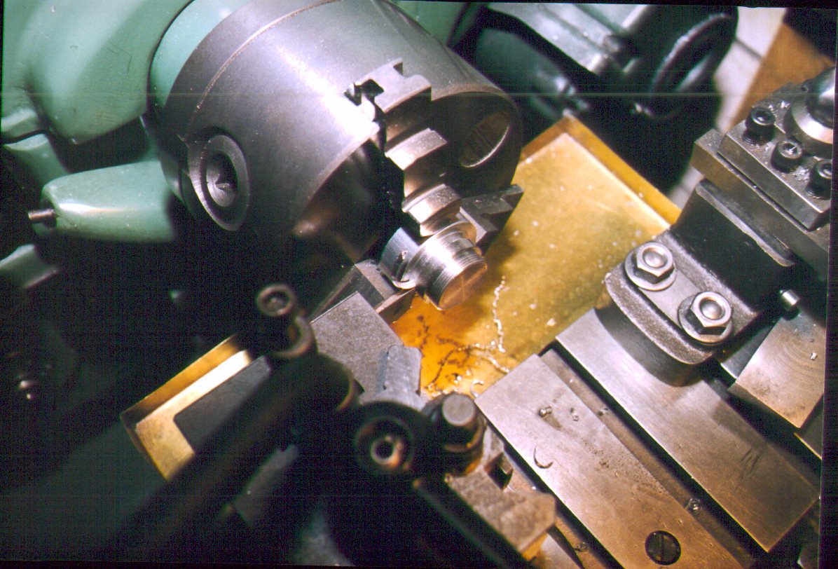
The backplate is simple turning with only some aspects of work holding posing any problems. I generally make male threaded parts before female, but sitting here, months after the event, I can't remember which way around I did these! In this first shot, the backplate profile has been turned on a piece of bar stock with the interior face oriented towards the tailstock. This means we will be screwcutting towards the sholder formed by the backplate rim, so a thin (0.020") runout groove is first cut at the thread/rim junction to the depth of the thread form. This also assures the backplate will form a tight seal against the rear of the crankcase.
The thread cutting tool is a piece of 1/4" diameter HSS steel, ground to a 60 degree point with seven degrees of side rake, mounted in a George H Thomas (GHT) retracting tool holder. This magnificant gadget takes a while to make but is absolutely invaluable to thread cutting. The little ball lever actuates a spring loaded, over center cam - just requiring a flick to retract the tool bit by about 3/16". This allows the saddle to be repositioned for the next cutting pass without having to twiddle dials and remember settings.
In use, the compound slide is set over by half the included thread angle, less a degree. This allows the cut to progress down the thread face, rather than just plunging in. Next, the compound dial is zeroed and the tool tip just brought into contact with the work OD using the cross slide. At this point, the tool is moved away from the work towards the tailstock with the saddle and the full depth of cut advanced with cross slide, which is then locked. The tool is brought back to clear the work with the compound slide and the first cut "put on". The thread is cut advancing first by 0.002" per pass and finally 0.001" per pass until the compound slide again reads zero. At this point, the thread is complete! Always remember to oil the thread before doing trial fits into the crankcase. A tight aluminum to aluminum thread will "weld" itself together all too easily and fair ruin your day.
After the thread is finished to provide a comfortable fit with the crankcase, the backplate can be parted off from the stub, as shown in this shot. Again, no rocket science, but do note the "V" shape of the chip forming. This shape slightly narrows the chip in relation to the groove, greatly assisting chip clearing. The shape is achieved by grinding a V in the top of the parting blate tip. I do this using a Dremel hand tool with a thin cut-off wheel. No great accuracy needed. Try it - I'm sure you'll like it (another great tip from GHT).
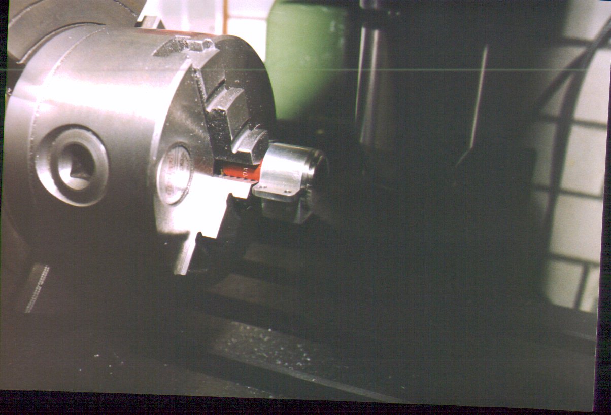
Finally, the external cavity for the backplate needs to be formed and this is the challenge in work holding mentioned earlier. The simple solution is to use a crankcase, chucked on its front journal to hold the backplate. Adequate concentricity is assured (close enough for jazz, as we used to say) and the only problem will be that the cutting forces will well and truly lock up the backplate into the crankcase! No problem. The chuck is transferred to the mill and a 1/16" slitting saw used to place a neat, horizontal slit across the backplate rim for the tightening tool. This allows the backplate to be easily unscrewed from the crankcase. The photo shows this operation about to commence, but due to flash failure in the days before my pathetic photography efforts went digital, the slitting saw is all but invisible.
![]()
Back to Weaver Journal front page