WATZIT?!
Model Engines of Unknown Origin
Page 2
Last update: Nov 28, 2005
Click on images to view them in larger size and more detail.
Quad Ball-Race .63
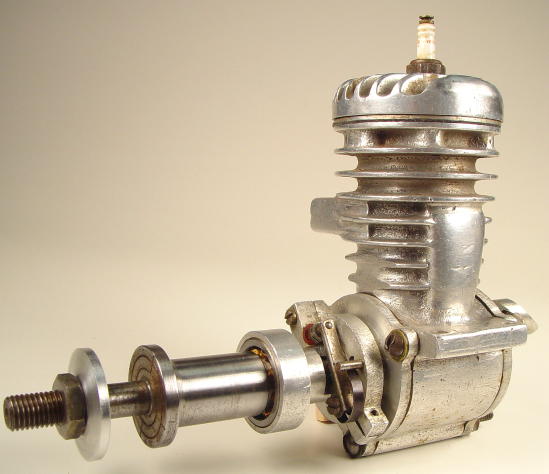
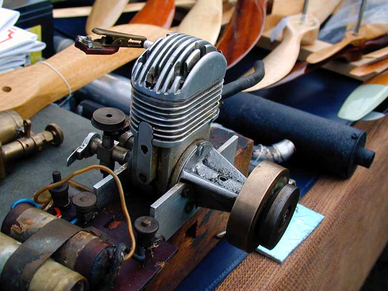
This one we feel is a custom, probably one-off item. It was very nicely made and features dual ball-races on both shaft and the rear rotary valve. Not visible is a sadly broken and butchered lower lip on the exhaust. Capacity measures about 0.63 cu in and it has a ringed aluminium piston. Looks to me like it was intended for speed use from the long (Mr Whippy) shaft that would facilitate very streamlined cowling. The styling is rather "modern" in an early 50's way, but the points setup with cam between the shaft races (a la' McCoy) argues for pre 1950, I'd say. Beats the hell outa me, Lieutenant...
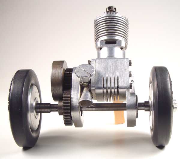
This unique engine came into Bert's hands courtesy of Ray Strinati. We quickly identified the engine as the same one appearing in Mike Clanford's A-Z of Model Engines. Now, just to prove that one should not believe everything one reads in MC's book, read on, as they say. First, Bert's account:
My old friend, Ray Strinati [says] it once held the 2.5cc speed record at 63 MPH. I measured the wheels at 2 1/2" diameter, which if my calculations are correct, the wheels had to be turning 8,470 RPM to reach a speed of 63 MPH. The engine is geared so that it turns 1.5 times as fast as the wheels, so that means the engine had to be running 12,706 RPM. I made no allowance for wheel slippage, and surely there would have been some.
The engine is very well made, inside and out. It has a screwed in place dural carrier for the wrist pin and the shaft runs in ball races. It is a crankshaft rotary valve type. The cylinder has four exhaust ports with four intake flutes milled into the inner wall of the cylinder between the exhaust ports, somewhat like a Webra Mach 1. The front and back plates of the engine carry the ball races that support the live axle. It is in good shape and would probably crank right up! Ray thinks it was made in 1948 or 1949, but was not sure. He was also not sure if Ron Flowers is still with us after all these years.
From the drive end of the engine, rotation is the usual clockwise direction. This means the engine operated with the cylinder trailing the front axle and the air intake pointing directly forward, which is logical. The wheel hubs are stamped "nearside" and "offside", which probably translates in Texan to Inside and Outside.
This is a precision built engine that must have been considered as a marvel in it's day. It is very, very nice even now. As far as I can tell, it is totally home built. Now if I can just find plans for his car!!!
Ken Croft was able to get in contact with a very knowledgeable source in the UK and managed to add considerably to the confusion. Ken says:
Now the plot thickens, as Mike Beach has come back to me about the "Flowers" engine. Once again, I am the reporter, not the source of the information.
In England, there is a small but enthusiastic band of tethered car addicts. Their leader, and editor of a small mag called "Retro" or some such, is a good guy called Peter Hill. Peter is the fountain of all knowledge on tethered cars in the uk, and their history. Mike has spoken to Peter about the engine. Peter says that in Retro, about 3 years ago, he published a picture of the engine. The picture had been sent to him by Ray Strinati, asking if anyone knew anything about it. At the time, Mike Beach contacted Peter to tell him that he had bought the engine from its maker, a chap called Ken Robinson, who at the time was living in Rochester Kent. This Robinson was also the maker of a batch of 12 engines called the "Speedwell". They were 10cc and not successful. A review of the Speedwell appeared in Model Engine World some time back.
Now Mike has again spoken to Peter Hill about the engine and it's possible "Flowers" connection. Peter says that to his knowledge [and his records are extensive], there are no speed records attributed to the name of Flowers, indeed, the name Floweres seems not to occur anywhere in his archives. What Peter does have apparently, is a picture if the so-called Flowers engine, in a tethered car.
Peter is a bit miffed about the Flowers attribution of this engine. He is a keen historian, and believes that if collectors are inventing false providence for items in their collection, that is distorting history and as such is a bit naughty. I explained to Mike, who will no doubt talk to Peter, that this certainly does not apply here, as the engine was a gift and there is no profit motive, nor attempt to inflate it's value. More likely a simple mistake or memory lapse, or Ray has been fed unknowingly with some wrong information. I don't think Peter Hill is on email but I will find out, as it would be nice to tidy this thing up, and to get a copy of the picture of the engine in it's car.
Ken snapped this one at Old Warden, 2001. An ambitious project:
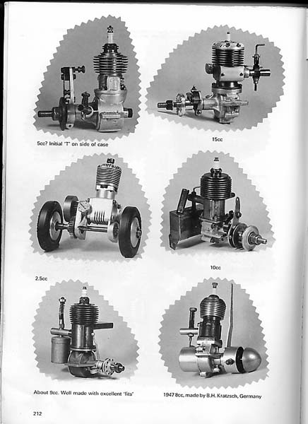
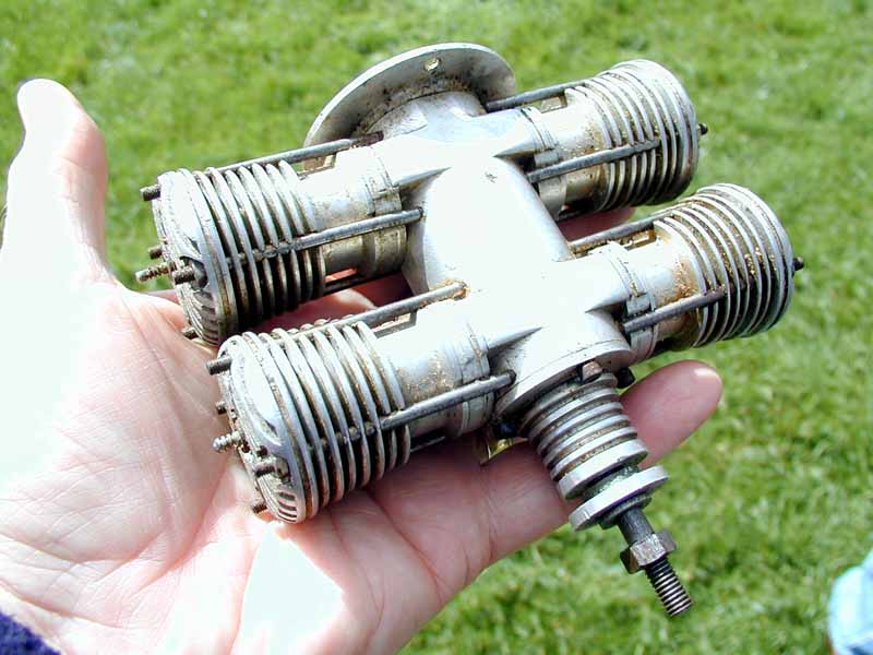
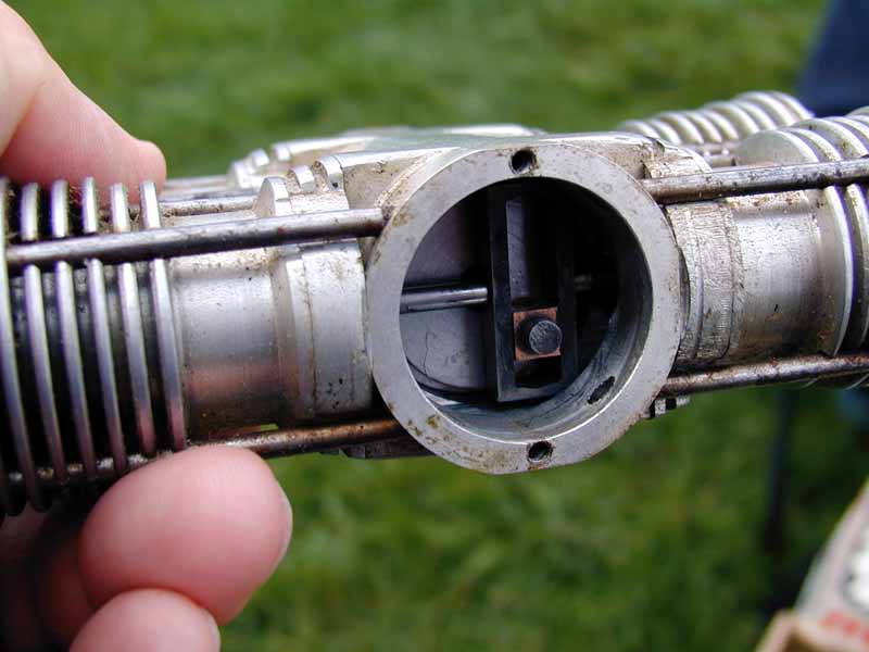
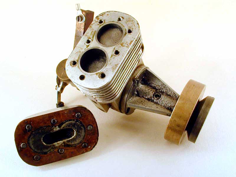
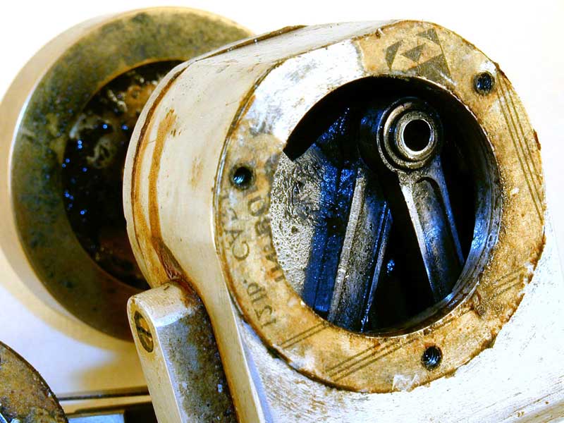
The flat 4 is an unfinished engine, quite old [although it had glow plugs] and the inside picture shows scotch yokes and no swinging conrods. There was no provision for an induction system of any kind, and we could not see where it could go. It was most likely to be a single rear disc with the front getting its charge through the hollow shaft. Lots of work had gone into an engine that stood little chance of ever running.
And to add my three pennith worth, note how the cylinder hold-down stud holes are tapped all the way through into the crankcase. Now even assuming the backplate occludes the rear ones, they are still going to bleed some case pressure. I'm also not too keen on only two backplate screws on a big backplate mounted engine with it's center of mass way up front. And a final word on Scotch Yokes in general from Roger Schroeder (with some words blanked to protect the guilty):
When I was at [...], my section head
had the idea that the very large bore and very short stroke was the engine of
the future. Thus he undertook the development of a scotch yoke engine
having a 5.5" bore and a 3.2" stroke. My friend who was the guru in
combustion demonstrated with a conventional crank/rod single CFR engine
that the combustion process in such a bore/stroke combination was really
terrible. There was insufficient turbulence to get any speed in the
flame front and the surface to volume ratio was a killer for heat
transfer. Another friend demonstrated to all our regret that when the
sliding shoe goes off center, there is a large force couple that
distorts the piston and leads to early failure unless the piston is
really beefed up. (just what is not needed is more piston mass, right?) None of
this deterred [section head] who pushed the project ahead until a 4 cylinder, 8
combustion chamber prototype was built and tested. This one proved the
poor performance and, when built strong enough and with all accessories,
did not give the small under-hood size that was expected.
The project quietly died. This was my first exposure to the fact that
all engineering decisions are ultimately political.
But wait (as they say), there's more! Years after what you've just read was posted, I found out that the engine had passed into Eric Offen's collection. Not only that, but Eric was kind enough to pull it apart for some more photos. Due to age and other factors, he had to take a hacksaw to the studs of one cylinder to do this, for which we must be most grateful.
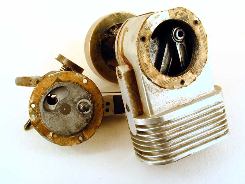
We now see (Photos 5 and 6) that the cylinder liners are brass and that they carry "conventional" exhaust and transfer port cut-outs. It's hard to say, but there may be a hint of chrome in the bore, and the piston looks like it may be aluminium. Photo 5 shows the square-edged exhaust; Photo 6 shows the transfer with the lower side rounded to assist gas-flow. If you squint hard at Photo 5, you'll be able to see a shallow transfer passage milled into the cylinder jacket opposite the exhaust opening. It appears that the liner may be shorter than the jacket, but we must assume that the piston, at BDC, will leave an opening to permit gas to enter this transfer passage.
Next, notice from Photo 1 that each cylinder sits on an aluminium platform that is separate from the case. David of Bourke Engines had emailed not long prior to this, suggesting that this Watzit was based on Russell Bourke's design where the volume under each piston is sealed around the Scotch-yoke rod--feasible because the rod's motion is linear--thus providing each cylinder with its own independent, two-cycle transfer pump. All that's now missing from our mystery engine is some means of delivering one-way fuel-air mix to the four "pumps" formed by these plates and the pistons. So the engine, as it stands, still won't run, but I think we can now say that the builder was following a workable concept.
Flowers/Robinson Tether Car Engine
A Scotch-Yoke Flat Four
Update: August 2004
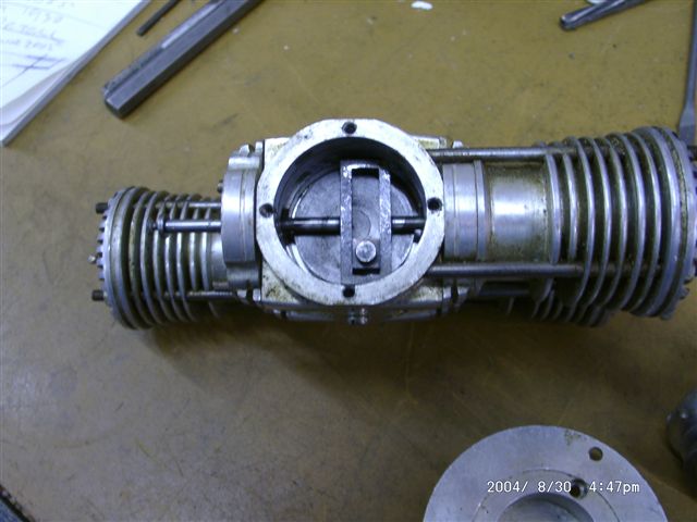 Photo 1
|
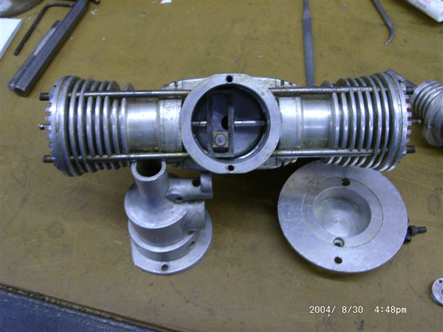 Photo 2
|
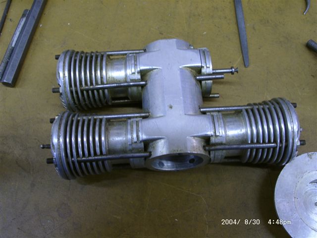 Photo 3
|
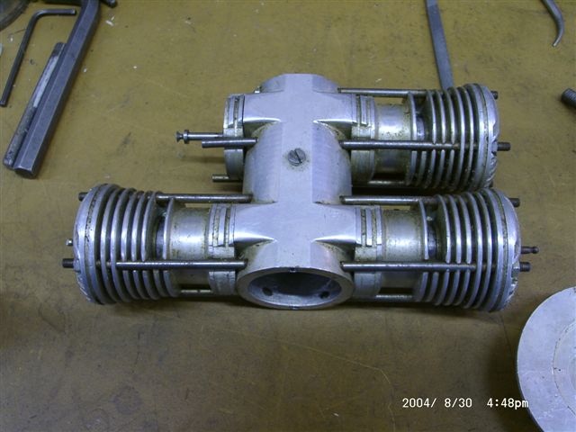 Photo 4
|
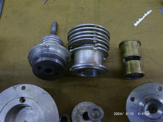 Photo 5
|
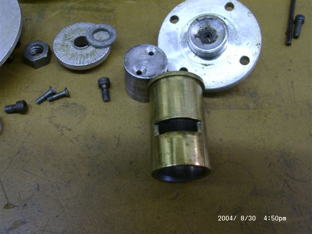 Photo 6
|
A Tiny Diesel
Ken at Old Warden, 2001 again:
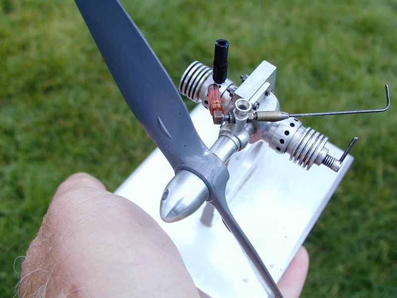
The little tiny flat twin is actually a single, with the other pot a dummy acting as a fuel tank. The owner was he who built the previously seen Vee twelve, and his father made it and flew it a lot, in the late 40's. It was probably about 0.2cc, and we could not get it to go due to being bunged up, and feeling worn in the bore. Interesting though.
I like the way the designer incorporated the venturi; sort of like the way Cox did on their TeeDee and Medallion series, except this seems a press fixture rather than being retained by a screw on sleeve at the front. The idea of the "fuel tank in the fake twin" was published in an early Aeromodeller issue (this engine might have inspired that drawing) and adds were placed for a commercial engine called "The Lionheart" that incorporated the same idea. This was advertised in 1949/50 as either diesel or glow with a capacity of 2.49cc.
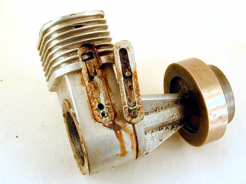
Ken Croft dredged this one up, so best let him tell the story:
Hands up, who noticed that the head fins ran transversely and not front to back?
Mike Beach picked this one up at the SAM Gala at Old Warden today (October 2001). One of our more senior engine builders believes it was featured in the Model Engineer about 1945 and he knows what it is, he thinks.
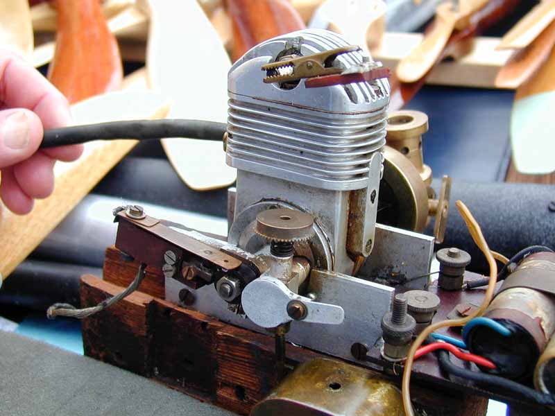
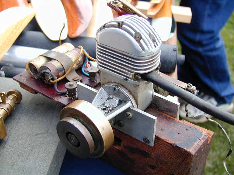
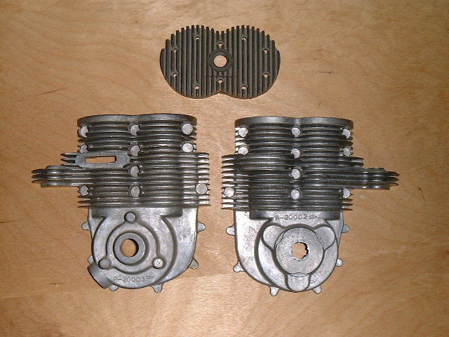
I tried to run the engine, but it just banged and would not pick up, so I have started to pull it down. It is as we suspected, a split single. It is 0.6875" bore and 0.75" stroke, giving a combined displacement of 9.125cc. The bypass does not open until the exhaust is fully open and the exhausting cylinder is at it's own BDC. The bypass then remains open at its own bdc whilst the other piston rises and closes its exhaust, then the bypass starts to close. The bypass remains open for a significant crankshaft rotation whilst the other piston is rising. If the engine ever runs, and I am confident that it will, it's Achilles Heel will be the transfer passage, which is machined into the transfer cover. It is only 0.15" wide, 0.085" deep, and 1.125" long. It connects to the crankcase by a hole only 0.125" diameter!
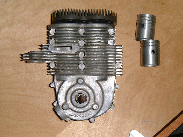
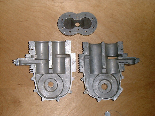
The pictures show the engine in its dirty state as I was pulling it down. In the picture of the bypass side, I have included the actual bypass cover. On the side of the case are 3 holes, the top and bottom are screwed for the cover bolts, and the second hole up is the tiny 1/8" diameter hole connecting the bypass passage to the crankcase.
The engine should run, but one problem is that there is a lot of leakage along the crankshaft bearing and out of the lubrication hole part way along the bearing. This is exacerbated by the fact that when running on a flywheel, there is no end thrust from a propeller to keep the crank disk sealing against the end of the crankshaft bearing. I will think about making a closer fitting bearing as it would be nice to see the thing running.
There is no reason to find rotary disk induction on a split single to be unexpected. Basically what happens with a split single is that the charge goes up the bypass through one cylinder only, to the common combustion chamber, it ignites then exhausts out of the other cylinder. How the charge gets into the case could be by any of our known induction systems, disk valve, rotary shaft, or sideport.
The crankshaft is centred between the cylinders.
I just measured the bore and stroke of one cylinder and doubled it. After all, they both suck in the fuel /air mixture! The only problem is that although they appear at first sight to be both at TDC at the same time, there is actually a small difference between them due to each cylinder being grossly "desaxé". The point where the cylinders are at the same position in the cylinder, is a few thou below tdc, but only a few thou. The other thing I have just realised, is that in a single cylinder 2 cycle engine, as the bypass closes before the exhaust, compression starts with exhaust closure. With this particular split single, the bypass closes well after the exhaust closes and only then does compression start. This means that the effective compression ratio is much less than for a single cylinder engine.
This is a more serious version of our previous Whatzit, or at least a nice set of die castings for one meaning someone went to a lot of trouble and probably did some prototype work we don't know about. Like the engine Ken examined (which he never did get to run before its owner sold it to a serious collector for a King's ransom), it features two heavily desaxé'd pistons. But unlike the other, it follows a more established design for this type of engine. The basic concept is two pistons sharing a common combustion chamber, with one "leading" the other and ported such that the leading piston is responsible for exhaust, while the trailing one handles transfer. The engine is called a "split single", or Twingle and was developed for use in Punch (Austria) motorcycles designed by Giovanni Marcellino in the 1920's. Sears even marketed twingle powered Punchs in the US during the 1960's.
I'll hand over to Stan Pilgrim here for a bit of a history lesson:
The configuration was adopted by Ing Zoller in 1931 and was to make DKW (Germany) the dominant racing motorcycle in the Lightweight and Junior classes during the pre war years. Up until then TT races were won by overhead cam fourstroke engines, the conventional two stroke engine of the day just was not good enough.
DKW also employed a third piston (3 cylinder single) which acted as a supercharger to force feed the crankcase. DKW tried piston port, reed valve and disc valve induction and had their greatest success with the disc valve setup.
Other companies that used split singles were TWN (German) and EMC (Joe Ehrlich, England). The first EMC bikes in 1947 had EMC designed engines but later machines were fitted with Puch engines.
The classic Puch layout was three transfer ports in the back cylinder with two exhaust ports and either one or two inlet ports also in the front cylinder (piston controlled inlet). The conrod had a main roller big end with a secondary sleeve bearing pivot pin at the fork in the rods.
A major draw back of the design was the mass of the pistons and conrods when compared to a conventional single.
A high performance 1957 model 250 SGSS Puch road bike would produce maximum power at around 6500 rpm and be capable of 100 mph with a fuel consumption of just over 20 miles to the imperial gallon when flat out. It had an exhaust note to wake the dead and vibrated that much that stress cracks would appear in the frame.
It had oil injection, dual ignition (poor combustion chamber shape) and two huge carburettors. The second carb would stay shut until about 80 mph and then would open rapidly (cam operated). With both carbs open and the air cleaners off you could look straight through the engine, look in one carb & out the other. It was shear excitement to ride back then, I know I had one.
The main reason for the split single idea was to have the exhaust port open before the transfer ports then close before the transfer ports thus preventing loss of fresh charge out the exhaust.
The idea worked well with an extractor exhaust system and or a supercharger but when Walter Kaaden introduced the resonating exhaust system that relied on the transfer port shutting prior to the reflected wave of gas being rammed into the cylinder the day of the split single had ended.
Examine the photo on the right and you can see how one cylinder looks like what we'd expect to see in a 2 stroke side port: inlet opening with the piston just before TDC and exhause opening just before BDC. Normally in a side-port design, all timing is symetrical about BDC and TDC (which is why they will run equally well in either direction), but on this beast, since the crankshaft/conrod geometry mandates that one piston must lag the other, transfer will not occur symmetrically with exhaust. Optimally, the exhaust would be fully open when transfer occurs, so the inrush of the new charge will assist to force out the remainder of the burnt gasses and the exhaust will close before the new charge get a chance to rush up one chimney, down the other and escape. So we should get better scavenging efficiency, with only some mixing of old and new charges in the transfer cylinder. Full size 2 stroke diesels built on this principle induct only supercharged air, with fuel being injected when this air has been compressed, hence their scavenging is just about as good as it gets.
Combustion will be a bit odd too. Lets assume that the engine uses spark ignition, so we can control where firing occurs, probably just on or before TDC of the exhaust piston. Mixture ignites; gasses expand; exhaust piston starts to move down, but transfer piston is still moving up (albeit at a different rate because of the heavy desaxé). For a period of time, the combustion volume will be if not exactly constant, then at least only changing slowly and the expanding gas will be pushing equally on both pistons, effectively fighting over which way the shaft is going to rotate and robbing power from what should have been the power stroke! However that scavenging efficiency also equates to low emission, a growing point of concern for all 2 strokes, so the design is not to be sneezed at. I must hasten to add that this is just my own armchair speculation and I could be entirely wrong.
Several sets of these casting must have been made. This set shown here were photographed by Tim Dannels (curator of the Model Museum) at well known collector, Doc Nicol's place in Washington state. Tim knows of yet another incomplete set in California. I remembered seeing them somewhere else and was lucky enough a few weeks after Tim sent the pictures to blunder across that somewhere again: the Aeromodeller Annual for 1974. It contains an article on multi-cylinder model engines and, amongst others, shows a set of these castings turned into a complete engine.
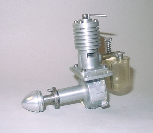
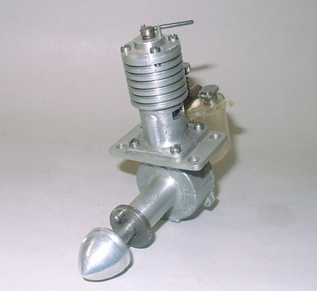
This one comes from Jim Dunkin. Jim says it has American threads and thinks it may have been made from a kit. None of the Motor Boys have a clue on this one. It seems to be well made and looking closely, we see it appears to be die cast (notice the fine parting line on the case and cylinder jacket). Design wise, it has aspects of the Dyno: a drive "peg" for the prop; a starting cord grove in the spinner nut; a stop on the compression screw. There may be a drain screw under the crankcase too. That would place it early-mid 1940's, design-wise. To me, the tank looks like a material that would degrade with time, so the engine itself may not be as old as the design appears to indicate, although the shiny Gitts cap and what looks like putty under the venturi tube may indicate that the tank itself is a later attachment. Email us if you have any clues to what this thing may be.
One hellova Whatzit
Variation on the Hellovawatzit Theme
The Split Single two stroke is an antiquated idea that was brilliant in its day.
For model use it would be just a heavy novelty engine.
Puch (Austria) started using the concept for motorcycles in the twenties. Their first split single being designed by Giovanni Marcellino.
A Diesel of Unknown Origin