How To Maintain Your Digital Vernier
![]()
Introduction
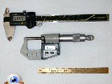
There are four types of measuring tool that will probably be found in a Model Engineer's workshop. Each has it's correct use and generally, the more accurate they are, the harder and less convenient they are to use. In decreasing precision they are, the micrometer screw gauge, the Vernier caliper, the steel ruler, and the Mk I eye-ball. Of these, the digital form of the venerable Vernier has become the instrument of choice for model engineers because it is readily available, easy to use, and cheap! In the old days, we called them "Very-near calipers", probably due to the degree of interpolation required in obtaining a reading. The digital readout has made that a thing of the past, or has it? I consider myself moderately experienced, but you are never too old to learn something and recently, I received a lesson in humility and tool maintenance. We maintain our cutting tools, but generally give no thought to the all important measuring tools, even though we should. Maybe everybody except me knows this, but I'll tell the story anyway.
The Scenario
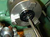
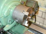
Here's the scene that began the path to enlightenment. I was facing back the center of some cast iron wheels in the 3-jaw chuck. Outside jaws had been fitted to the chuck, the rear of each piece had been faced, then the outside diameter rough turned normal to the face. The next step was to seat the faced side against the step of the chuck jaws so the axel hole could be drilled and reamered (as the Brits would say). The last step for this setup was to then face the hub back for a three decimal place precision in thickness. The geometry of the setup made it impossible to get behind it to even measure the thickness at the rim, let alone the center. It could be removed for measurement, but this would be time consuming, and would upset concentricity and lead to the danger that the front face and hole might no longer be at right angles. How do you make the measurement? Enter, stage left, the chuck back-stop.
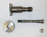
The device seen here was made several years back to a design that appeared in the Model Engineer, I think. It does not get a lot of use, spending most of its time hanging on my shadow board, as attested by the small spots of surface oxidization, but when called into service, it is worth its weight in gold. Naturally, it's designed specifically for the Myford ML7 spindle, but could be adapted to other lathes. The front section slides into the lathe headstock spindle from the opening in the lathe's left-hand end cover. It is split four ways and the right-hand end has a shallow, internal famale taper.
The other component has a matching male taper and is fitted with a threaded collar that will pull the tapers together. The inner taper has a rollpin that rides in one of the slits of the outer part of the to prevent rotation. When drawn together, the male taper expands the end of the outer part to grip the spindle bore securely. The operation is identical to that of the Myford manual headstock spindle handle, but in this case, the male part is drilled through 1/4" and is also split on the end so that when the outer part can expand no more, it forces the inner part to close. This will firmly grip the 1/4" rod at any position you place it. On the end of the rod is a replaceable pad which forms the actual back-stop.
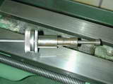
Here's the stop in action. The rod has been fed right up to the chuck. When the work has been gripped, drilled and reamed (rest-of-world terminology this time), the back-stop can be pushed against the rear of the work so that a depthing tool such as a standard Vernier caliper can be used to measure the thickness of the work—provided there is no burr on the hole exit. Fortunately reaming the hole will remove any burr resulting from drilling, leaving a minimal one in it's place that can be ignored.
The Surprise
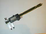
After facing a number of wheels to 0.375", I casually placed one between the normal inside jaws of my high-quality, Mitutoyo digital calipers. Ghasp! Shock! Horror! Oh the Humanities, they all measured 0.371" thick. Now 0.004" is not a lot between friends and I can compensate without a problem in this case, but there would other instances where this would be a complete disaster and the parts would now be residing in the scrap box.
This is not the sort of error one expects from even a budget digital Vernier, let alone a supposed high-end one. What's going on? Either this tool is complete rubbish, or something has changed since I bought it in 1998. I was sure it was not always like this; in fact, I was absolutely certain! But it sure was now, so when and how did it happen? The calipers have never been dropped, or subjected to any use other than the intended one. There are no obvious burrs or corrosion on the jaw faces. The under-reading on depth suggests that the "probe" is sitting 0.004" proud of the end when the jaws are closed and reading zero, but careful inspection under magnification reveals no obvious protrusion. Repeating the measurement on another piece over 1" in length gave the same 0.004" over-reading error.
One possible cause of an error like this is the depth measurement was made at an angle, possibly owing to the rather thin "anvil" offered by the end of the calipers. But my calculator tells me that to produce a slant reading of 0.375" over a horizontal distance of 0.371 requires and angle of some 8.4°. I rather think I'd notice that, so let's look for another cause and start by checking the accuracy of the inside jaws by comparison against another, higher precision instrument.
Using a piece of 0.625" drill rod, the micrometer reads 0.6247". Closed up to gently contact the test piece, the Vernier reads 0.625. Pushing tightly, the reading changes! The harder I push, the smaller the reading gets! Using light pressure, the Vernirer can be made to read 0.624", but it's so touchy, it can be made to read just about anything!
The Cause
With the test piece placed well up in the jaws, the calipers read 0.624", virtually regardless of the pressure applied. Placed at the tip and pushing the calipers very firmly together can produce a reading as low as 0.6115". Obviously the movable jaw is deflecting when the point of contact results in a long moment arm. Has something worn, or is there another cause? You are probably way ahead of me by now.
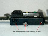
Like a lathe slide, the movable jaw of the Vernier caliper is fitted with an adjustable Gib strip. In the case of the Mitutoyo (and most instruments of this type), there are three Gib adjusting set screws, the central one being extended so it can be used to lock the head. It came as no surprise to me that upon applying a jewelers' screw driver to the front set screw, I found it so loose it was not contacting the Gib at all. The rear one was better, but still loose. Adjusting them so the movable jaw slides smoothly, but with a smidgen of "feel" cured the problem. The Vernier now reads the same as the Micrometer with moderate pressure. Applying excessive pressure moves the reading by 0.0005". I can live with that. I now observe a 0.0005" difference between the inside jaws and the depthing probe. I can live with that too.
The Conclusion
Micrometers are fitted with a ratchet on the end for a very good reason and that is to prevent just the sort of abuse I was subjecting my Vernier calipers to. In fact the micrometer ratchet makes it near impossible to induce a force-fed error. Unless the Gib of your Vernier is well adjusted, it is disgustingly easy to obtain an under-reading by varying the pressure applied to the movable jaw. With the Gib adjusted correctly, the effect is minimized, if not entirely eliminated. The location of the work in the jaws has an effect too, so adjust your Vernier Gib screws periodically, and where possible, place the work high up in the Vernier jaws. Better still, use your micrometer when truly high precision is required (and make yourself a micrometer stand).
![]()
This page designed to look best when using anything but IE!
Please submit all questions and comments to
[email protected]
Copyright (c) Ronald A Chernich, 2010. All rights reserved worldwide.
