How To Wire Up A Sparkie
Do you have an old spark ignition model engine that you'd like to try running, but don't have a clue how to wire it up? Don't be embarrassed. More and more, it seems that knowledge which once was common, is passing into legend and obscurity, and model engines are no exception. On this page, we'll look at old and new ways of wiring up a "sparkie", and give a few hints and tips that may help you relive the joys (?) of a bye-gone era.
The theory behind the spark ignition system has been well investigated in many other publications, most of which seem to disagree with each other to some degree. In order to reduce confusion, we'll restrain ourselves here to the "how", and provide a References Section for those who'd like to pursue the "why". We are also going to ignore magnetos and capacative discharge ignition (CDI) in this discussion, although we will look at transistorized switching.
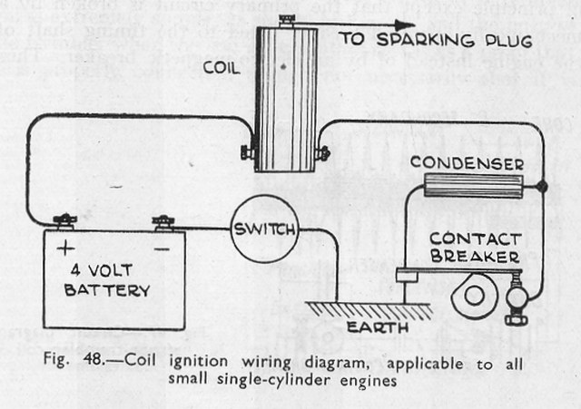
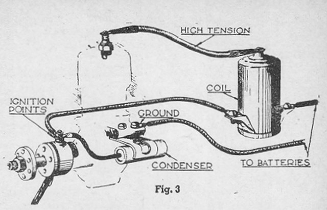
The "classic" circuit used for model spark ignition engines is an adaptation of the one invented by Charles F Kettering and initially licensed by Cadillac for their 1911 model, and which we've been been using in one form or another ever since. The wiring is really quite simple, as shown in this schematic taken from Model Petrol Engines, by the late Edgar T Westbury. For many, this diagram will be all that's required, so we could stop now. But if you did not grow up in the era of the sparkies, it may look rather mysterious, compounded by the fact that there is considerable variation in detail between spark ignition components, so let's start off by looking at the common components in general. These are:
The Contact Points
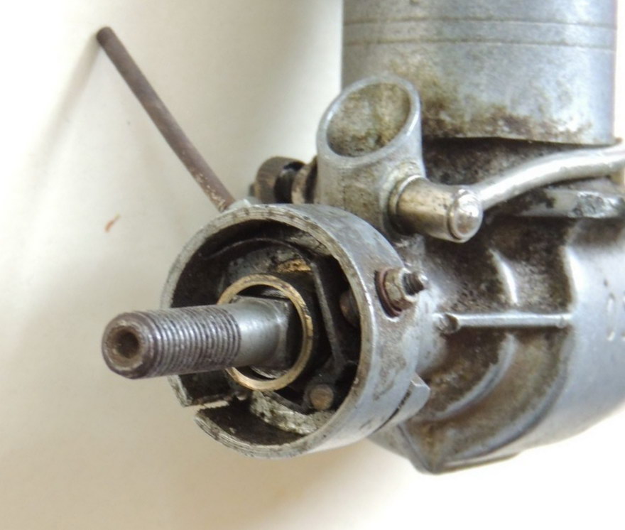
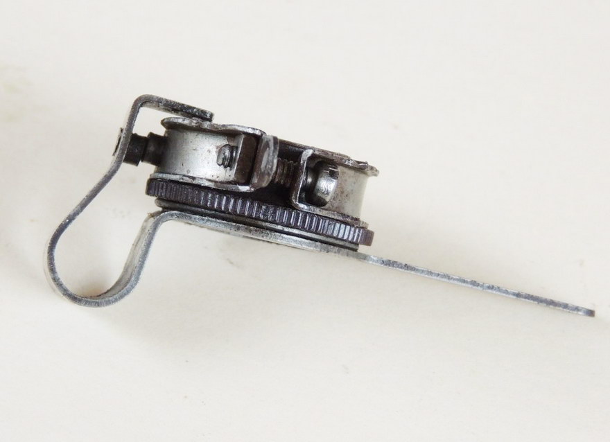
Model spark ignition engines have a set of "points" (aka, "contacts", or "timer" assembly) which are closed once per revolution by a cam attached to the engine crankshaft. The angle of rotation during which the points are closed is typically 60° and is known as the "dwell". One point is electrically insulated from the rest of the engine, the other is generally connected to the engine crankcase.
You may see the terms "fixed" and "movable" in relation to the contacts and think the point that is actuated by the cam is the movable one. It ain't necessarily so. The purpose of the points is to allow current to flow through the ignition coil primary winding for a short time during each engine revolution. The physical separation between the points when they are open is generally made adjustable so that the dwell can be altered. This is done by making one of them movable in respect to the other. Frequently, this movable point will not be the one that is moved by the cam! Luckily, none of this matters a toss. What is important is that one of the points is insulated electrically from the rest of the engine, while the other is not.
Generation of the high voltage which creates the ignition spark is initiated by the opening of the points. In almost all cases, the whole timer assembly can be rotated in relation to the cam allowing the position at which the contacts open in relation to top dead center (TDC) to be adjusted. This allows us to adjust the time at which the spark happens (hopefully) in relation to the point of maximum compression. This action is referred to as advancing and retarding the spark. To achieve maximum power, we want the spark to occur at some time just before TDC, but this can make the engine difficult to start. If we move the timer in the same direction as the crankshaft rotates, the spark will occur later, making the engine easier to start, but robbing us of power. This is called "retarding the spark". Moving the timer assembly in the opposite direction to the engine rotation advances the spark, so retard to start, then advance when running.
To do their job, the points need to offer low electrical resistance when closed. A downside to provision for advance/retard adjustment is that the mechanism may introduce undesirable electrical resistance, or even unreliability, especially when dirt and oil are added. For this reason, a design where provision has been made to connect the wiring as close as possible to the actual points themselves is an advantage as it places no reliance on mechanical contact between the crankcase and timer assembly for the point ground connection. A good ground connection is still required though for the high tension circuit.
The Capacitor
One authoritative source who should know better says that there is a difference between a capacitor and a condenser. There isn't. When two electrically conductive surfaces are separated by an insulating dielectric—which may be air—they exhibit an electrical property which we can measure, and call "capacitance". Once upon a time, and principally in the US, such devices were known as condensers.
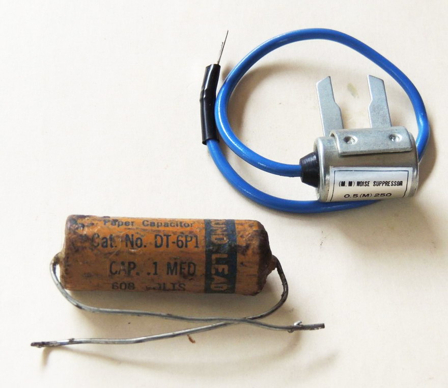
Regardless of what you call them, the property in question is measured in Farads (after Sir Michael Faraday), but since a whole Farad is a very large and dangerous thing not often encountered anywhere, we conveniently prefix it with "micro" as it's much easier to say "I'd like a 0.2 micro Farad capacitor please", than "give me a 0.0000002 Farad condenser", which is what you'll be looking for as the thing to wire across the ignition points mentioned above. The normal abbreviation for a micro Farad is "μF", "uF", or "mF". The F is always a capital letter because it's a person's name. The lower case "m" is an abbreviation for "micro", which should be represented using the Greek letter "mu" (μ). The use of the lower case "u" is a convenience for representing μ using typography that lacks Greek letters.
The optimum value required will vary with coil design and characteristics, but it is not particularly critical; a value between 0.1μF and 0.5μF will be fine. However, another property of a capacitor is its working voltage. This is the maximum voltage that can be safely applied across it before the insulating dielectric breaks down. For reasons lost in time, the working voltage is represented as "VW" (volts, working). For our requirements, a component rated for about 150VW is required. More does no harm, but as expected, a higher working voltage imposes a thicker, or different dielectric material, requiring more plate area for the same capacity, so size and weight go up.
The Spark Coil
The spark coil—"coil" for short, and "induction coil" for long—can take many forms, and has! Its purpose is to convert the low battery voltage—typically 3 to 4 volts—into a very high voltage; one high enough to ionize air and cause a spark to jump across a distance of 0.02", or more, under several atmospheres of pressure. This requires a voltage of around 15,000 to 20,000 volts. I've been a bit vague here on purpose, as what goes on in the Kettering circuit is rather complex for something so seemingly simple. Many books have been written on the subject, and disagreement over the details are more common than not!
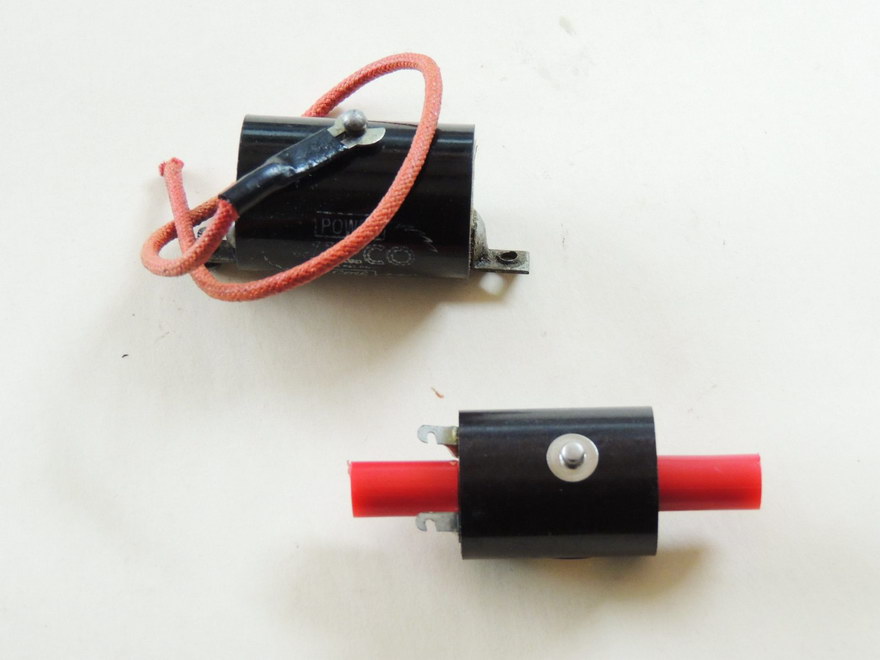
The coil comprises two windings of enameled copper wire around a bobbin through the center of which passes a soft iron core—almost inevitably laminated plates, or even lengths of wire. The primary winding carries a high current, so it is wound using a low number of thick wire turns. The secondary winding will carry only a very small current, so it uses a very high number of thin wire turns. The ratio of turns will be in the region of 1,000:1, or more. You can make your own coil, but it's a major undertaking, so generally you'll buy one. Those made for model airplane use are small, to keep weight down. This makes them sensitive to voltage (and hence, current), so for test-running, many model engineers outfit themselves with a motorcycle coil. This is way too heavy to fly in a model, but is reliable, robust, and gives a good, hot spark—that being just what the doctor ordered when dealing with old engines, or shop-made ones.
An ignition coil will generally have three connections: a high tension connection which supplies the 20KV to the spark plug; a low tension connection which is wired to the insulated contact point (and via that, to ground); and a battery connection which is connected to either the battery positive, or the ignition switch. In theory, it should not matter which battery terminal is connected to the coil, positive, or negative. Some assert it does make a difference and you should try both to determine which is best, although how you measure this is not mentioned.
A three connection coil will be acting as an "auto-transformer" where the primary voltage effectively adds to the secondary to provide most bang for your buck. At the moment the points open, the collapsing magnetic field will produce a voltage in the region of 150 volts across the primary winding (from a typical 3 volt coil). The turns ratio, primary to secondary, transforms this into the high voltage required.
The Spark Plug
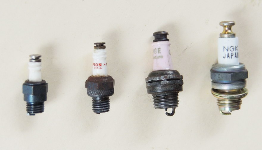
The spark plug, or "sparking plug", as the British charmingly prefer to call it, has an insulated electrode to which the coil high tension is connected by an insulated lead. As twenty thousand volts is nothing to be sneezed at, the high tension wiring and the spark plug deserve some respect. It will not, and cannot kill you, but it may tickle a bit. Spark plugs for model use, once as common as dirt, are still available, but are somewhat rare even though the quality is better than that of their heyday. The spark is formed when the air gap between that insulated central electrode and another attached to the sparking plug body breaks down. The distance a spark will jump in free air for a given voltage is inversely proportional to the pressure. That's to say, you may observe a nice enough spark with the plug outside the engine, but that's no guarantee you'll get the same—or any—spark under the increased pressure due to compression of the mixture in the cylinder.
Note too that the body of the plug forms the second half of the electrical high tension circuit, so if you are continentally connecting your ground wire to the engine mounting lug, the circuit starts at the spark plug thread and gasket. It then travels across the cylinder head, through the cylinder liner, and hence to the crankcase, with some gaskets and bolts thrown in for confusion in most cases. All resistance robs you of high tension volts, so good, clean connections are the order of the day.
Modern spark plugs for model engines use the same 1/4-32 thread as that used for glow plugs. You may also encounter a 3/8-24 thread on very old engines. NKG make a 10M1 plug (10mm diameter, 1mm pitch), and many model engineers have successfully made their own spark plugs, with thread to order. The spark gap varies by maker too, but 0.02" (0.5mm) is a ball-park figure.
Battery
If you read old magazine plans from the Good Old Days, you will find designs using a 4.5 volt "cycle battery". You'll also see the use of two 1.5 volt dry cell batteries wired in series for 3 volts. Today, you might see reference to wiring three NiCad batteries in series for a total of 3.6 volts. But NiCads are growing hard to find as various lithium based cells have become all the rechargeable rage. Confused? You should be. The "real" answer lies in the coil, which will have been designed to operate at a specific primary voltage and whose resistance governs the maximum current. Apply too much voltage and you risk burning out the coil. This can also happen if the correct voltage is applied for too long (more on that later).
Coils have a property known as "induction", which is measured in Henrys (after Joseph Henry who did pioneering research in this field). A property of induction is to resist a change in current flow, so when our battery is connected across the ignition coil primary winding via the ignition points, it takes a while for the current to rise. This buildup is exponential, and again, I refer you to the references if you want more detail. What it all means to us is that at running speed, the time during which the points are closed (the dwell period) should be long enough for the primary coil current to approach the maximum, ensuring the associated electro-magnetic field also approaches the maximum. As the engine speed while we are flipping the prop is going to be much less, the dwell duration will be longer, so the time during which our battery will be supplying current is going to be way longer than is necessary.
Some have written that the current drawn is less when the engine is running. This is not accurate. We could say that the average coil current is lower when the engine is running because the dwell duration is optimal and we are not wasting as much energy. The objective is to get as much energy into the coil's electromagnetic field as its design allows, without wasting power, which is what happens as we reach the flattening top of that exponential curve of current verses time through an inductance. At that point, we are just wasting power heating the coil, which does neither it, nor the battery any good. I've seen Kettering circuit explanations that say we want to "saturate" the coil's core. Rubbish. If the core can magnetically saturate before the current reaches close to maximum, it's a badly designed coil.
Because of this starting drain on the battery, you will often see provisions for a "booster" battery to be plugged into the circuit for starting purposes. This is simply a higher capacity battery of the same voltage, connected in parallel across the normal battery so that the applied voltage does not change (which would damage the coil). Its purpose is to reduce the load on the lower capacity flight battery while starting, thus extending its life.
The Switch
An essential item for two reasons. On the surface of it, you may ask why? The point actuating cam assures that the circuit to the coil primary is open most of the time, so current can't flow. But if the points should close with the engine off, the battery is going to drain, and worse, the coil will be in danger of overheating. There are a couple of places we can place the switch, either between the coil and battery, or between the battery and ground. The latter is the most common. The switch should be capable of passing the full primary coil current, which will be in the vicinity of three to five amps. A quick acting toggle switch is preferred to a slide switch as with the latter, there is the danger that if turned on or off while the points are closed, the relatively slow sliding action of the switch contacts can lead to arcing in the switch, which can pit the contacts making them less reliable and higher resistance, or even weld them shut.
Wire
Connecting all the above requires insulated wire of some form. Today, PVC covered multi-strand, tinned copper wire is generally used. It is going to be exposed to heat and oil, not to mention vibration, so good quality solder joints and good quality wire are called for. As mentioned above, the primary circuit of a standard spark ignition setup is going to have to carry three to five amps. The high tension lead will be at 15,000 to 20,000 odd volts above ground and will be being vibrated like crazy while doing its thing, so good insulation and flexibility are essential.
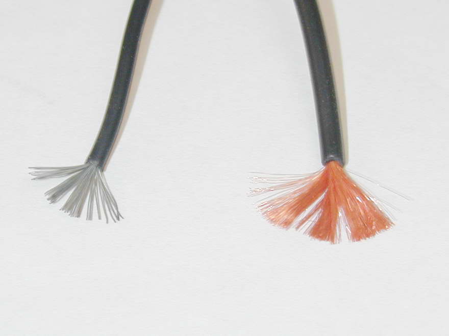
For the high-tension wire, you can't beat the sort of stuff used for electronic test equipment leads. Test-leads spend their entire life being bent, tugged, pulled, tied in knots, and stood on, while quite possibly being exposed to some rather inhospitable conditions. Accordingly, they are made with lots and lots of very, very fine strands about 0.001" in diameter. This makes the lead very flexible, with extremely low electrical resistance. The insulation is both thicker and made of a totally different compound compared to normal hook-up wire. You can actually rest it against a hot soldering iron for some time with no more than cosmetic damage. Today, this insulation is generally silicon based and so will be unaffected by exposure to a variety of oils and solvents, hot or otherwise. Naturally, there is an extra cost involved, but it is not awful and you can buy it by the meter at any reasonably stocked electronics warehouse in black and red at the very least.
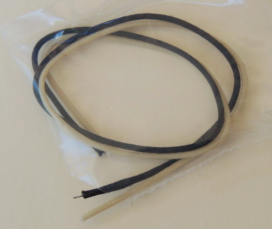
While modern materials are fantastic, old sparkies were wired up with a wire whose insulation was woven and impregnated. There are virtually no advantages to using this, except that it looks cool! The modern equivalent is called "push-back wire" and amazingly, it is readily available as it is used extensively for wiring and rewiring vintage electric guitars. If it has an advantage, it's that you don't have to strip the ends to solder it up. You just push back the insulation to expose some bare wire, solder up, then if necessary, push the insulation back down the wire. All very neat and it really looks the biscuit on a vintage sparkie. You can buy it by the roll, or by the foot from luthier supply houses line Stewart-MacDonald.
Classic Wiring
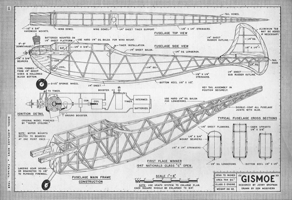
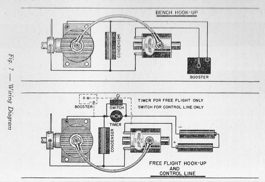
Hopefully, this has answered your questions about how it was done in prehistoric times. Plans of the period would often include a wiring diagram, as shown on this one from 1948. Notice it has no switch. The designer seems confident that the flight-timer would serve double duty as the master switch and engine cut-off. Not an unreasonable assumption, and saves the cost and weight of a switch as well.
Modern Wiring
So what has changed? All agree that the timer/ignition points are the weak link in the old ignition system. This is because they are so susceptible to dirt, oil, contact pitting, and other aggravations which tend to increase their electrical resistance, which reduces the primary coil current, leading to a weak or unreliable spark. Because of the constant hammering they are subjected to, tungsten was the material of choice, and it is not a great conductor to start with! Clearly, the first choice for improvement is the points.
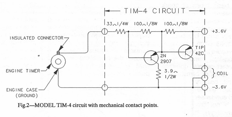
One improvement became possible in the 1960's with the advent of cheap transistors. The idea is to keep the engine timer assembly just as-is, with all its problems, but use it to switch a transistor on and off. This requires only a few milli-amps of current, so in theory, dirty points, oil, etc, won't matter. The points bias the transistor either totally on, or off, and when on, it carries all the amps required by the ignition coil primary circuit. As a bonus, we no longer need the capacitor. For a really good time, watch the experts who wrote reams about the "real" purpose of the capacitor in a Kettering circuit tap-dance their way around why it is no longer required then the mechanical switch is replaced by an electronic one.
The circuit above was devised by Floyd Carter and appeared in issue #21 of Strictly Internal Combustion magazine (SIC). Others abound, but this is as good as any and the transistor types quoted are still available.
Pointless Ignition
Since everyone agrees that the most problematical aspect of a spark ignition setup is the ignition points, the logical thing to do is find an alternative. The advent of semiconductor devices has made this a practical approach, first by using a photocell and a light source, with a rotating mask between to emulate the closed period of traditional ignition timer points. Later, the Hall effect transistor was developed. This device is switched on by a magnetic field. In both cases, there is still the requirement for a mechanical device rotating with the crankshaft to provide the pulse of whatever to trigger the transistor which makes current flow in the ignition coil primary winding. But this is not a bad thing as it allows us to mechanically advance and retard the ignition to obtain the optimum performance from the engine.
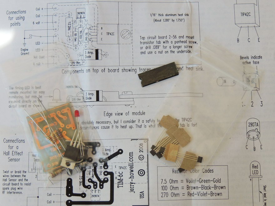
Of the two, the Hall effect device requires less work to implement and is more reliable, having a lower component count. The mechanical aspects of mounting the miniature rare-earth magnet which will activate the Hall effect transistor still requires precision, but not to the degree required to manufacture and spin a disc between the light source and photo-diode (or transistor), frequently in a light-proof enclosure. Circuits for this form of pointless ignition have been published in magazines like SIC, and Model Engine Builder (MEB).
References
- Westbury, ET: Model Petrol Engines, Percival Marshall & Co, London, (undated).
- Westbury, ET: Ignition Equipment, Percival Marshall & Co, London, 1948.
- Shores, R: Ignition Coils and Magnetos in Miniature, 1997.
 Back to the Construction Techniques Index Page
This page designed to look best when using anything but IE!
Please submit all questions and comments to [email protected]
