Workholding with Pot-Chucks
Holding parts for second and subsequent machining steps can be quite a challenge. If you are just starting out in model engine making, you may be tempted to look at a job and think that your three-jaw self-centering scroll chuck looks like it might just do the job, if you take really light cuts... don't even think about it; there's no substitute for solid workholding. On this page we'll look at a simple device which takes only a few minutes to make from scrap, but which will make light work of second operations on things like prop drivers, backplates, cylinder heads, and the like.
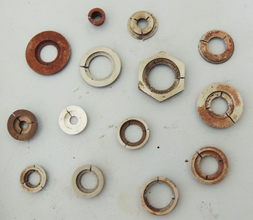
This photo shows a pile of pot chucks made over the decades (as if they don't show it) for various jobs. All have been machined from some off-cut, generally steel, of a size appropriate to the thing to be held. They consist of a shallow cup, or "pot", with a hole in the middle and a flange around the outside. The ring is cut through in one place, and sometimes slit to the pot wall 60° either side of the through-slit, on the outer or inner flanges, or both.
The general idea is to make the "cup" diameter a close fit on the part to be held so the three jaw chuck will compress the pot-chuck, holding the work tightly. The depth of the pot-chuck gives the three-jaw chuck something to grip onto and the outer flange locates it against the scroll chuck jaws providing more stability, and as the cup was machined with the flange against the jaws, a high degree of concentricity and repeatability—more on that later.
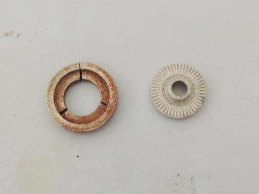
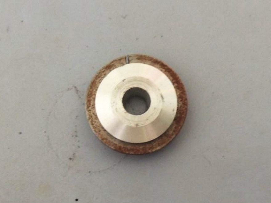
Here's an old prop drive washer (for the Sugden Special). It has been face-knurled and has a central spigot to locate the prop. First machining operations were completed easily while the driver was the end of a length of barstock. After drilling undersize and parting off, it needs to be faced to thickness, chamfered, and reamed with a tapered D-bit reamer to fit the propshaft collet. It should be obvious that unless the prop driver is held so the knurled face is normal to the lathe axis, the driver will induce a disastrous and unacceptable wobble on the spinning propeller.
The pot-chuck is machined from the rear first, producing the outer part of the cup and the rear of the flange. I generally make the walls and flange about 1mm (0.040) thick. The job is then reversed in the lathe and the rear of the flange pushed firmly into contact with the front of the self-centering chuck jaws for the remaining operations: facing to final flange depth, boring out to the required size and depth, then drilling and boring out the center.
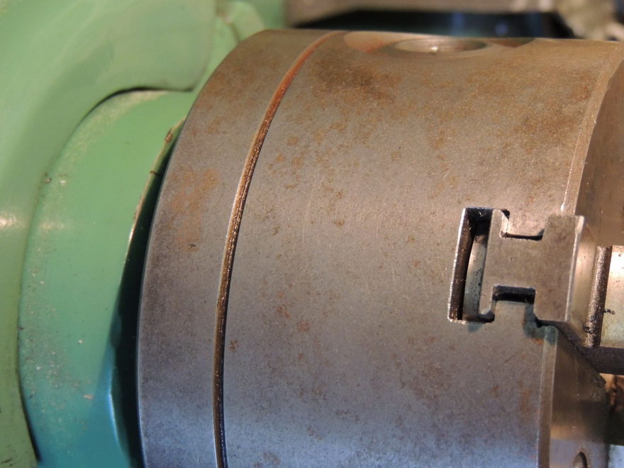
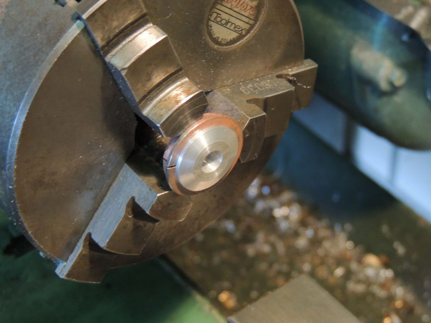
At this point, the core of the pot-chuck is running perfectly true, but all scroll chucks have a degree of run-out, so we must now mark the pot-chuck so when we place it back in the three-jaw chuck, it will be in close to the same orientation as it was when we machined it. To do this requires some fore-thought. As you probably know by now, the jaws of your scroll-chuck must be inserted in specific locations. To enable this, each jaw and each slot of the chuck is numbered, one to three. But these are hidden when the jaws are inserted, so unless your chuck is already stamped, stamp a "1", or some other mark opposite the #1 chuck jaw (as seen in this photo if you look closely on the backplate). Use this mark to place a light center-punch mark on the flange in the middle of the #1 jaw piece. You can now remove and replace your pot-chuck with the best chance of retaining concentricity.
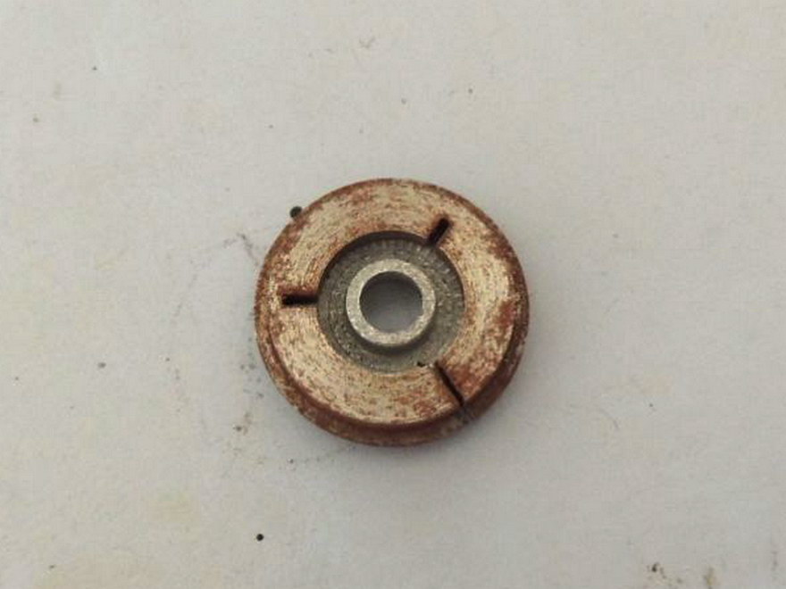
All that remains to be done is to scribe a diameter through the center-punch mark, then cut through the pot-chuck opposite the punch mark. If the pot-chuck is large, or the walls are thick, consider sawing through the inner and out flanges 60° to either side of the through-cut to better allow the pot-chuck to flex and grip your work. Generally, if the cup is a good, close fit on the job, you won't need to do this though.
I could have said more about determining how deep the pot should be, but really, that is obvious—the important part is in marking the jig so it can be replaced correctly before use. Swarf in the three-chuck scroll will also impair concentricity, so clean it regularly. You'll find many uses for pot-chucks in model engineering. I think I read about them first in the QUORN Book, by Professor Dennis Chaddock, where he used them to face steel washers to very specific widths, as determined by trial fit, in order to position the ball handles in the best position for convenient operation of his tool and cutter grinder. I doubt there is any other way that job could be accomplished.
![]()

This page designed to look best when using anything but IE!
Please submit all questions and comments to
[email protected]
Copyright (c) Ronald A Chernich, 2004. All rights reserved worldwide.