Turning Large Radius Curves

This tip shows a painless way to form a relatively large radius using the typical, light-duty, model engineers' lathe. Although the example shown is a concave curve, the technique is equally applicable to convex curves as well.

The task at hand is to make the prop drive "spool" for an ETA 29, Model "A". The part was completely absent on the engine being restored, but some research turned up 3-view drawings from an old issue of the Aeromodeller. A scan of the page was layered onto a CAD drawing page and scaled until the diameter of the spool matched the measured diameter of the front bearing housing casting. The scanned drawing also carried an Imperial scale, so after re-sizing the image, the scale was measured and the 1" divisions were found to be only 2 thou oversize (A, below). Amazing. A dimensioned drawing was then made by tracing over the scanned image (B).
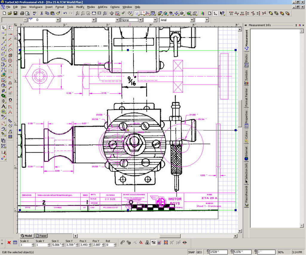 A |
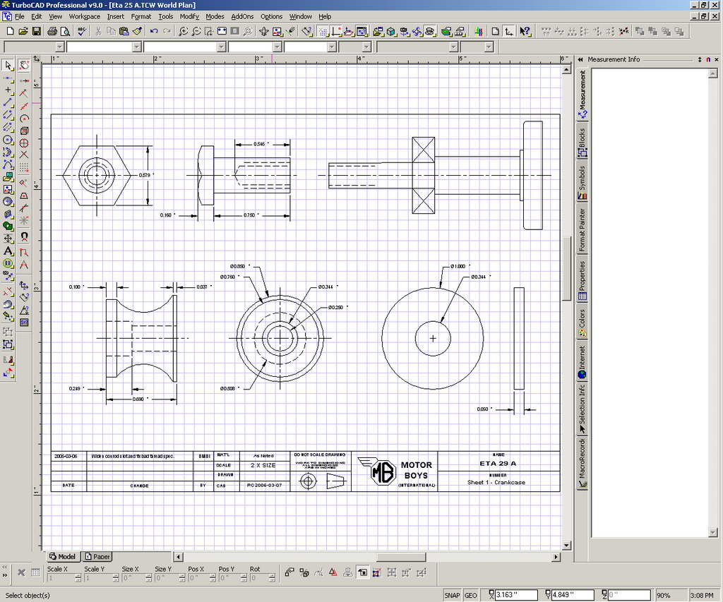 B |
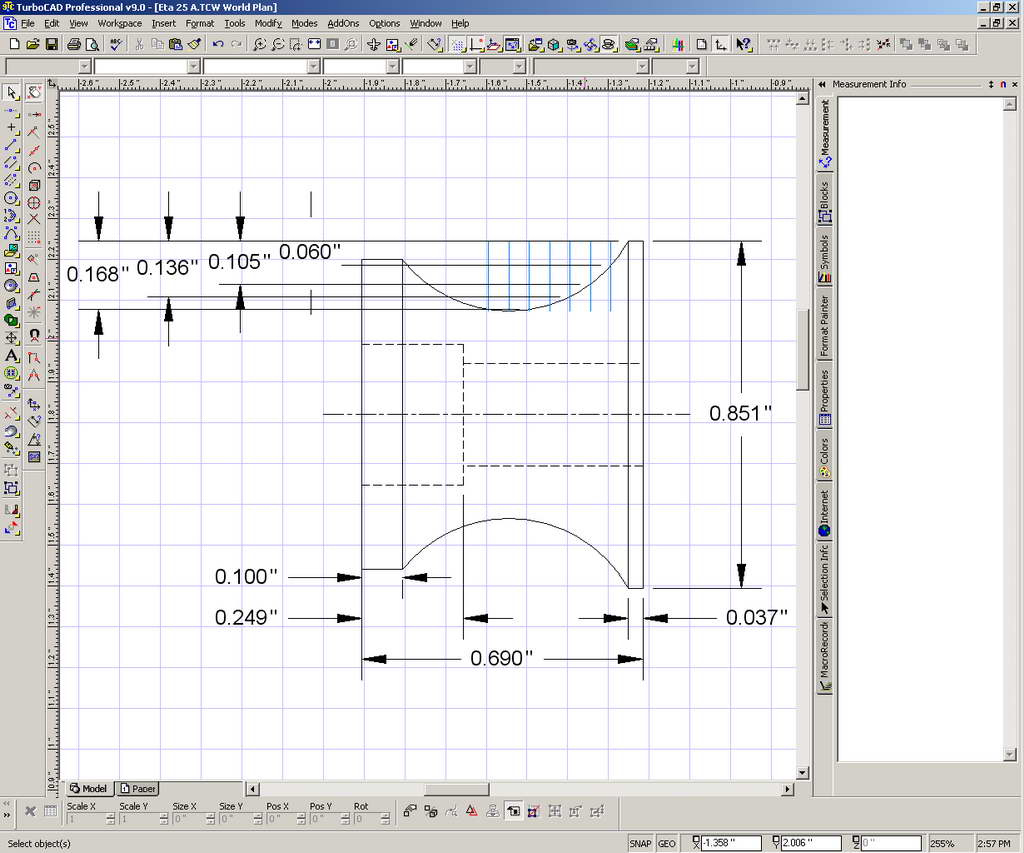 C |
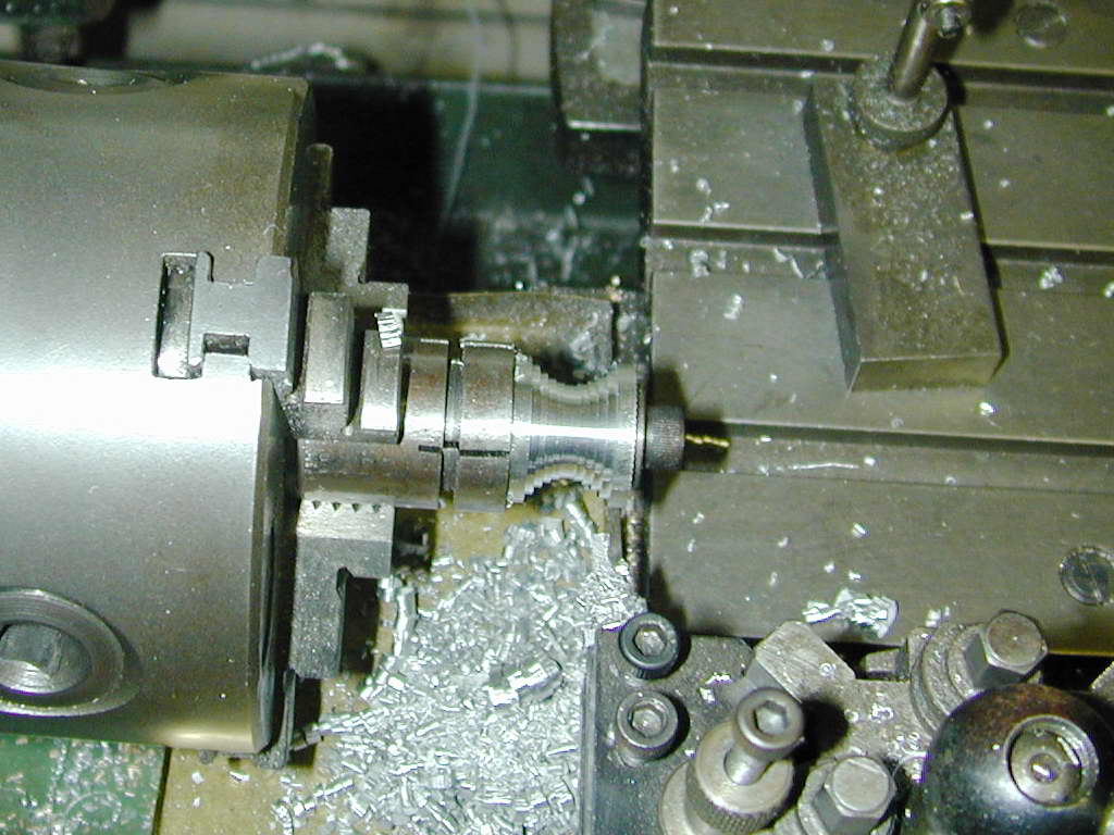 Here's stage one. A plunge has been taken, 0.100" wide, at the center of the curve. The tool is then moved 0.050" in each direction and another, easier cut made to the next measured depth. I actually dis all the ones on one side, followed by all the ones on the other so that the backlash of the compound slide would only have to be taken up once. I allowed 0.005" extra on each cut for a bit of extra smoothing on the final step.
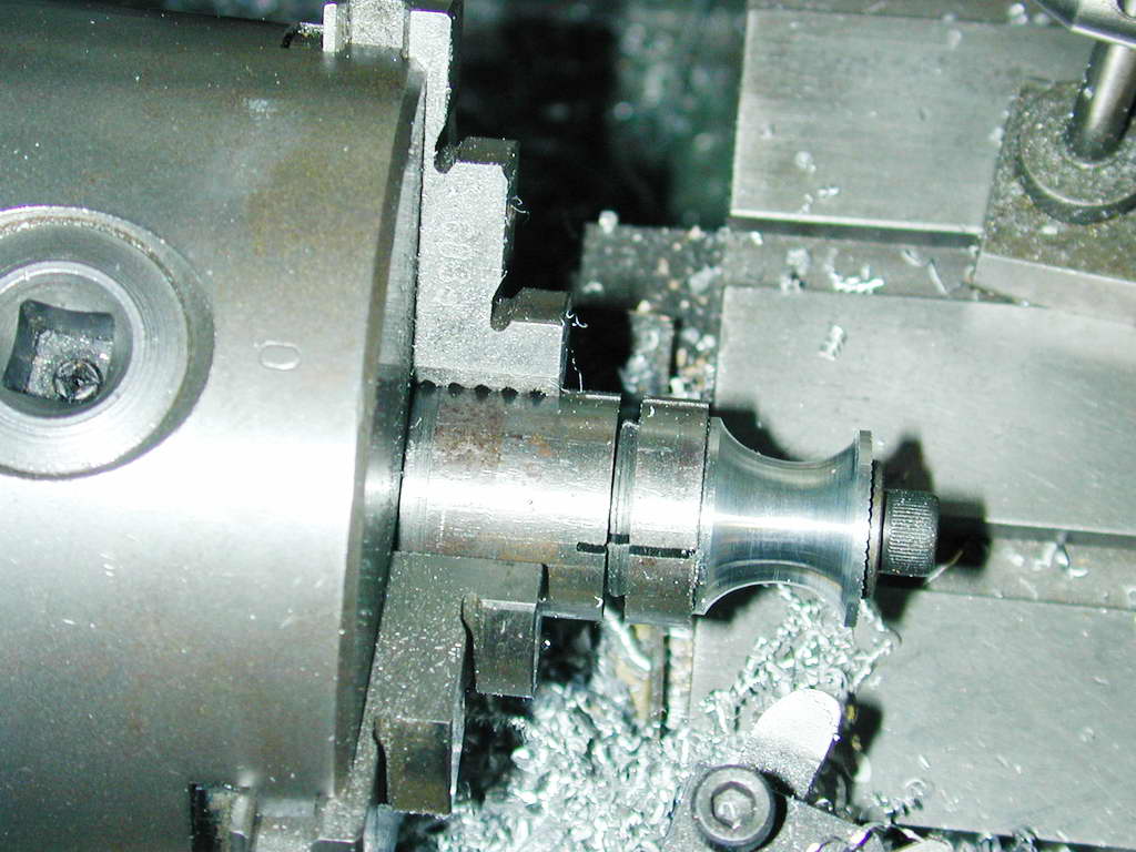 The last step is to use a tool with a large nose radius to smooth out the steps to turn away the "steps" so that a smooth curve is formed that connects the corners of the plunge cuts. This could probably be done better with a hand-graver, but lacking one of those, judicious two handed juggling of the cross slide and compound slide wheels produced a job that needed no further attention.

This page designed to look best when using anything but IE!
Please submit all questions and comments to
[email protected]
Copyright (c) Ronald A Chernich, 2004. All rights reserved worldwide.