How To Tighten Head Bolts
Hover for popup titles.
![]()

On this page you'll read a strategy for tightening the head bolts on model engines which have such things. It came about after I saw a diagram in a respected magazine suggesting a sequence for tightening the bolts on a typical six-bolt head. The sequence initially struck as wrong, until I realized they were talking about one style of engine, while I was thinking of another. But the unwary could apply one to the other and cause a distortion that the sequence was intended to prevent! Clearly what is required is that model engine owners understand the problem, then be able to work out the most appropriate sequence to avoid distortion, or poor seating.
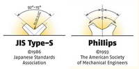
Before launching into that, I strongly suggest that you review the April 2011 Tech Tip on selecting the correct screwdriver for the job. I've lost count of the number of model engines I've seen with completely butchered screw heads due to a previous owner applying too much force to the wrong screwdriver for the screw type. This can lead to screws which can no longer be removed without dangerous surgery. These days, screwdriver insert sets are cheap and readily available. Get a comprehensive array so you'll always be able to select one that is correct for the job (and not worn out from previous abuse).
Head Types
When it comes to heads with hold-down bolts, there are three basic types:
- The cooling jacket which clamps a cylinder liner down into the crankcase. Many diesel engines use this arrangement which commonly has three or more long screws. Two bolt heads are not unknown in small diesels.
- A thin head which clamps down on a cylinder liner flange with the liner completely enclosed by the crankcase. This type will generally use a four or more short screws.
- A thin head which clamps down a cylinder liner which incorporates cooling fins. Generally, these will have an equal number of long and short screws, though engines using two longs and four small ones are not uncommon in the smaller displacement engines such as the Glow Chief shown below.
 Type 1. |
 Type 2. |
 Type 3. |
Sure, there are other variations, but these three are the most common.
The Problem
What we want to happen is for the head, regardless of the screw configuration, to exert equal pressure at all points around the cylinder liner which it is pressing into the crankcase. This will not happen if one screw is firmly tightened down while all the others are loose. In the case of Types 1 and 3, this can pull the whole liner to one side, increasing friction and inducing adverse piston wear. On all types it can also lead to compression leakage (primary, or crankcase pressure on Type 1, cylinder compression on the other two).
The Strategy
To prevent this, we need to tighten the screws a bit at a time, alternating so the head and liner are pulled down equally. If you fully tighten one first, it will go down further than it should and the others will not be able to go down as far as they should. We need to get the screws to act against each other in a balanced way. Suitable strategies for the three types are:
- Tighten one screw lightly. Tighten the opposite screw to the same amount, then any other, and its opposite number. Repeat in the same sequence, going for firm. Go around one last time aiming at tight, but not so much that the slot, or cross point is in any danger of being burred.
- Apply the same strategy as for Type 1. Generally this type of head will have an even number of screws, but an odd number is not unknown. If that is the case, do all the odd numbered ones first (counting around in a circle in any direction), followed by the even ones. Again, aim for three passes of equal tightness.
- On this type, tighten the long screws first, going to full tightness in the usual three passes, then repeat for the short screws. As before, tighten them in opposite pair sequence, if possible.
In all cases we are looking for a sequence which gradually presses the head and cylinder down without creating any force which might pull down one area more than the rest.
Conclusion
By this time, I'm sure some of you are saying all the above is obvious. It may well be, but evidence suggests there are many owners to whom it was not all that obvious.
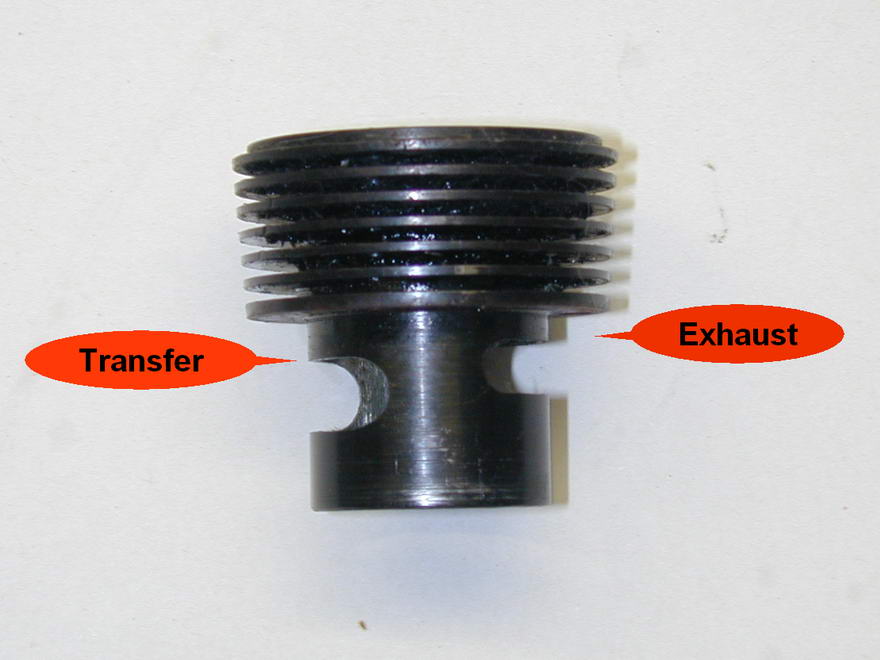
As a parting shot to all, I'll add that in the case of Types 2 and 3, it is possible to put the liner in two ways. The wrong way is with the transfer port aligned with the exhaust opening in the case! An engine will run like this, but is will be hard to start and gutless. This is another problem we've seen all to often—in at least one case, on an engine new from the factory! If in doubt, remember that the transfer should open after the exhaust, so the top of the transfer port opening will be lower than the exhaust port top. A quick check will save all sorts of embarrassment and cursing.
![]()

This page designed to look best when using anything but IE!
Please submit all questions and comments to
[email protected]
Copyright (c) Ronald A Chernich, 2012. All rights reserved worldwide.