How To Machine Cooling Head Fins
![]()
To me, this is one of the most satisfying and rewarding jobs in model IC engine making, as after the fins are cut, the engine really starts to look like an engine. However, cutting those fins can be stressful and discouraging: all is well, then--usually on the last fin--the tool momentarily digs in
, and before you can react, there's a *bang* and you're looking at a broken tool and a ruined job wobbling eccentrically in the chuck. In another scenario, the thin fins all assume a lean to the right due to friction heating of the left hand side of the fin being formed on the right; most unattractive.
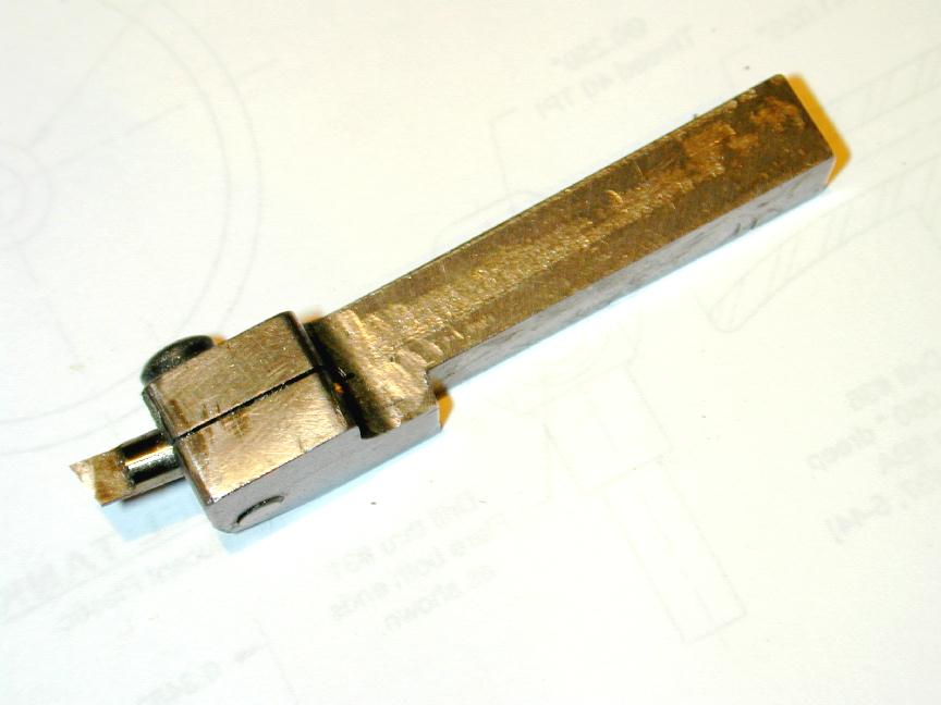
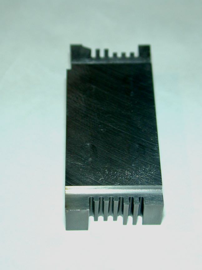 Commercial manufacturers are concerned with production costs and time. So to them the cost of having a special purpose tool made that cuts all the fins at once, finally rounding the ends and roots, is more than justified. They also have honkin' great lathes that can cope with the stresses of plunging such a tool into lump of metal that is being flooded by cutting lubricant. The tool seen here was cut by "wire erosion" to precisely the required rakes and clearances for the Peter Burford .33 cc diesel. In earlier days, cutters have been made by ganging together blades made from disks of tool steel or gauge plate, or even old power hack-saw blades. This is not beyond the capability of the average home shop machinist, but the power required to use them, and the rigidity needed to ensure they don't deflect and dig-in, are usually beyond our modest machines.
So we are restricted in most cases to cutting our fins one at a time, with the attendant potential dangers mentioned before. Believe me, I've had both these disasters occur, but (famous last words) that is all now a thing of the past. There is a secret and it's a simple one: you just need the right tool for the job.
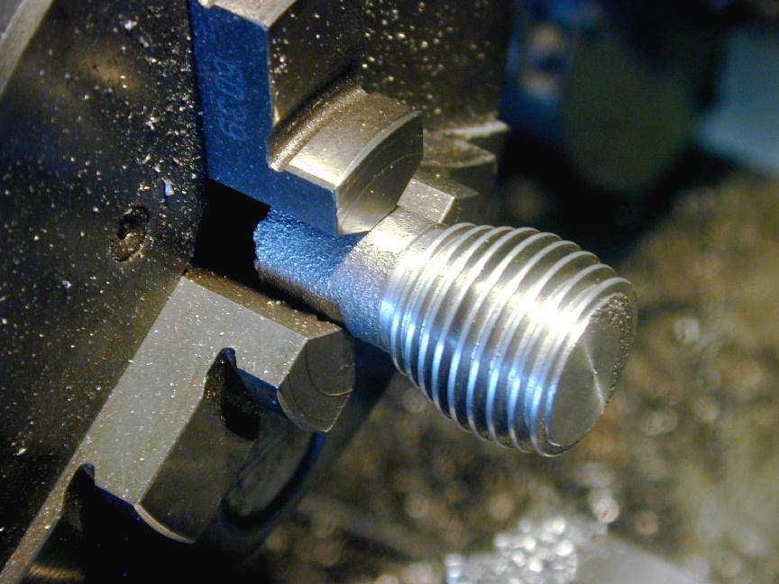
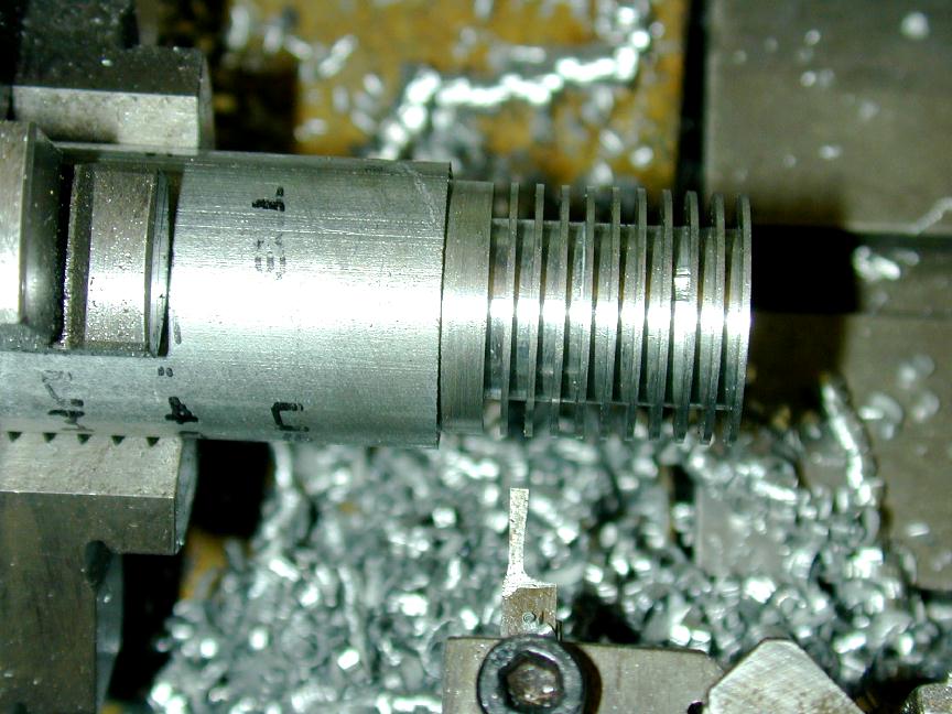
 The "right tool" is one that has zero side rake, sufficient side clearance on the front and back sides, and that is relieved on these sides so that only the cutting tip is actually contacting the job. The tool seen here is the tool that was used to cut the fins on the heading photograph. It has been ground from a length of 3/16" square High Speed Steel (HSS). Front clearance is 10 to 15 degrees and this particular tool has zero back rake. Each side of the tool has 3 degrees each of clearance and relief. Experts would say that the latter is excessive and weakens the tool near the root, precisely where it needs to be strong. They may be right. I'll just say that after adopting this shape, my tools have stopped breaking and my fins are straight--even wafer thin steel fins like to 0.5mm (0.019") ones on the Nova-1.
The disadvantage with the shape is that any subsequent touch-ups on the grinder will result in a tool that cuts a narrower gap. However, I've found that initial sharpening lasts and lasts. Besides, as we shall see, for a job like fin cutting, we can easily compensate of a tool that is not precisely to specification.
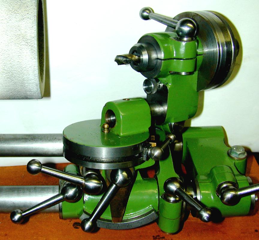
As to how these precise angles are ground, well there's no easy way to say this, you really need some kind of tool and cutter grinder. And believe it or not, it was failure scenario #2 (the leaning fins of Pisa) on the third engine I attempted, that gave me drive, desire, and energy needed to build the QUORN tool and cutter grinder. This is a complex and versatile device that took over six months to complete. If this is not to your taste, or timescale, there are simpler machines like the "Stent" and "Worden Mk III". The latter is more than adequate, and relatively easy and fast to make, while the Stent is nearly as complex and versatile as the Quorn. If you are more inclined to throwing money at the problem, there are relatively inexpensive Asian T&C grinders that can do the job quite well. Now while I'm sure there are talented folk out there who can grind an acceptable tool "off-hand" on a bench grinder, the average amateur machinist is going to need a tool for this purpose. Accept it, embrace it, do something about it, and then get on the the job.
 I generally don't bother with tailstock support for the job unless the amount of stock I have available for chucking is significantly less that the depth of my chuck jaws (as when using an offcut from the scrap box). First, reduce the blank to the finished OD and face the end (sometimes I bore and thread internally before cutting the fins; sometimes after--it really does not matter). Then with the tool set on lathe center line height and "square" to the job, touch the right hand side to the face of the blank. The fins can be spaced using the top slide, or a calibrated handwheel on the lead-screw if your lathe has one (like the excellent Myford series of model engineers lathes).
Whichever, establish a reference on the dial, wind the cutter clear of the work and advance by a distance equal to the sum of the required gap and fin width. The plan may say Gaps 0.056", Fins 0.025". Maybe your tool is a thou or two under or over. You could grind a new one, or you could just accept that this engine will have slightly wider fins or gaps. The really important dimension is the sum of the two; in this case, 0.081". If you use this to advance your nominal gap cutter, the last fin (or gap) will come out precisely where it should and all will be well.
 If the shape of the head is tapered or profiled, this should be done before cutting the fins. If left until later, the operation would burr and may damage the fins. However if the fins are "stepped" (different diameters, but with tips square to the head), it's easier to reduce them to size after cutting as producing the stepped shape beforehand is too potentially error prone to be worth the significant effort.
Touch the tool tip to the OD of the blank and zero the cross slide dial. Determine how deep to cut from the plans. I generally cut aluminium at the slowest, or second slowest non-backgear speed I have available; ie, between 260 and 300 RPM. If I hear chatter, then I know I need to go to a lower speed. So start-up and wind in. Just like parting off, never pause with the tool tip against the rotating job. If you have to pause, back off a little. You can use cutting lubricant if you want. Experience with your tools and machine will eventually tell you what works best for you.
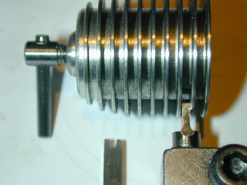
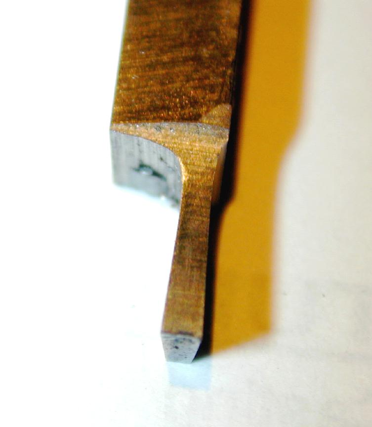
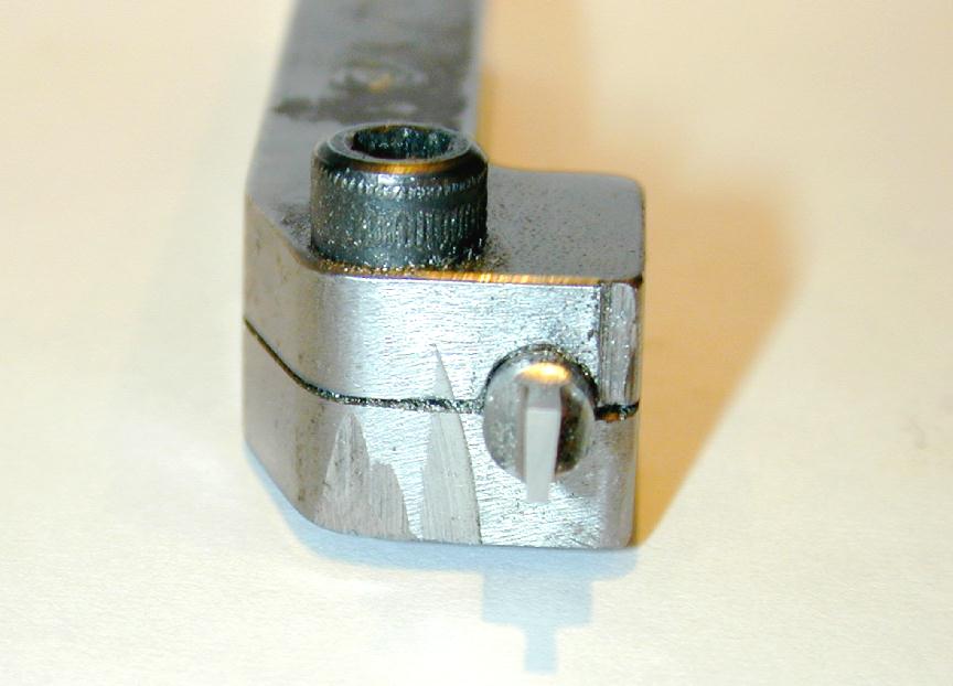
Some engines, particularly older ones with aluminium cooling jackets like the Mills and Prototype Taplin look better with neatly profiled tips to the fins. This can be done with a fine Swiss pattern needle file and fine emory paper, but a far superior job can be achieved with a form tool. In the posed photo above, we see such a form tool made from a piece of 1/8" square HSS. The front clearance was ground in, then a little slot was ground using a Dremel cut-off wheel. These will cut a slot about 0.025" wide, but best of all, as the extreme edges of the disk wear quickly, they will cut a slot that is radiused at the end--just what we need! The tool is mounted and positioned centrally over the first fin. Start-up and wind in until the tip is radiused, noting the depth you have cut to. Now advance exactly as before to position over the next fin. Repeat 'til done.
|
|
|
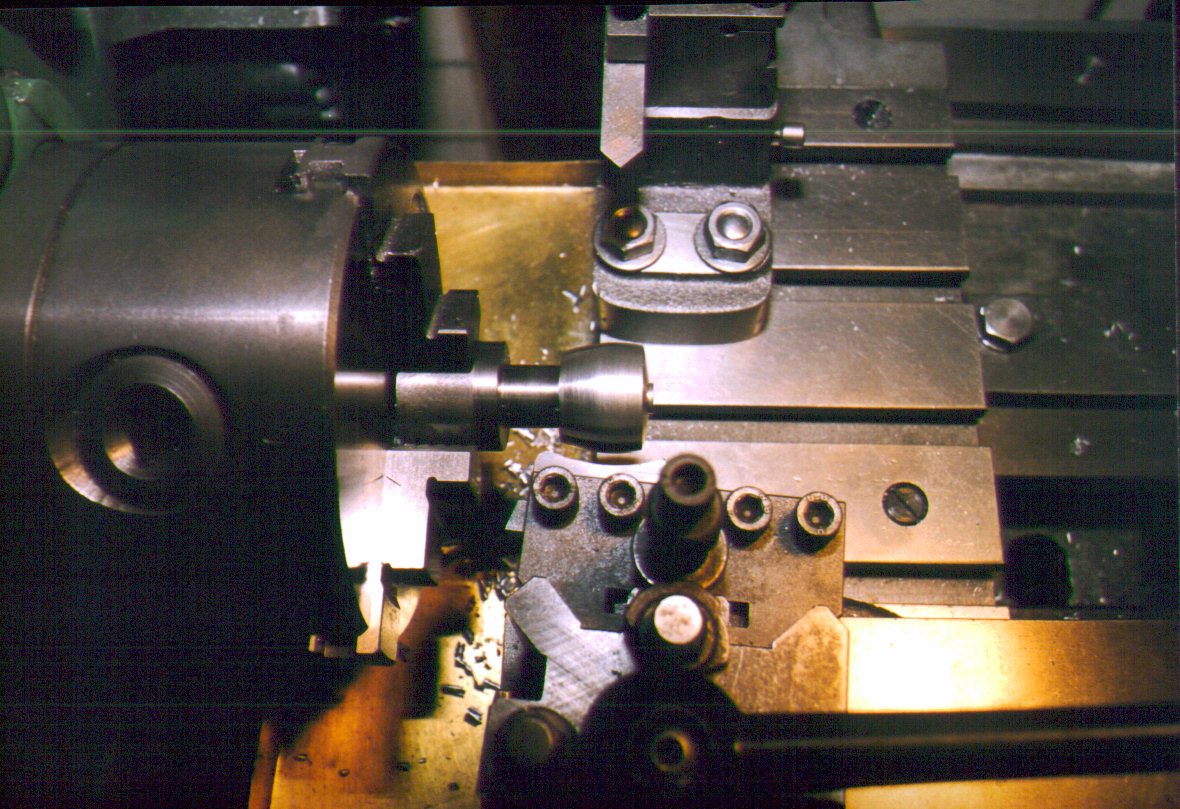
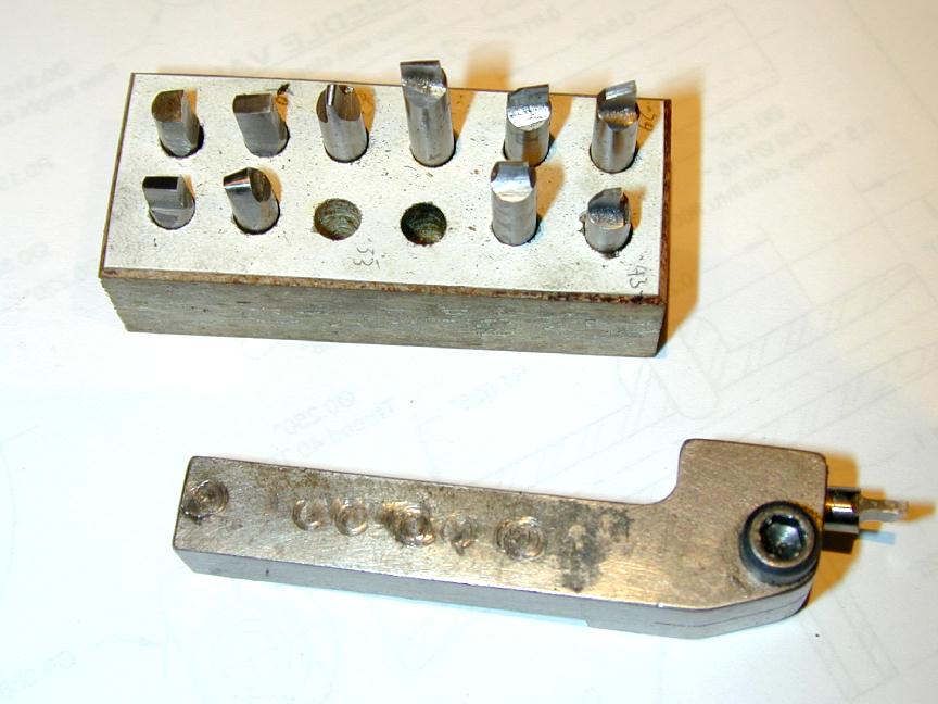
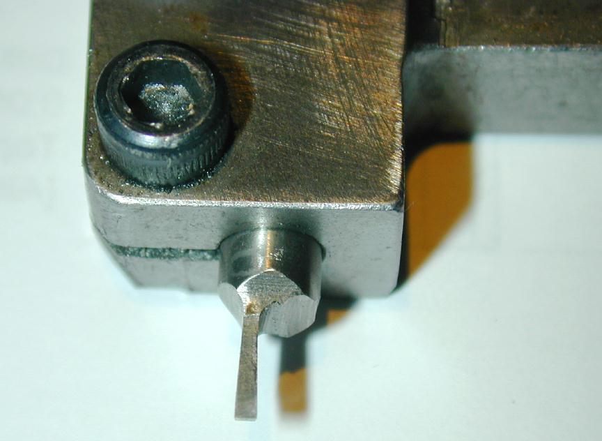
Here's another tool that is far more economical on HSS consumption. It uses 3/16" round HSS stock and is made to the design appearing in that essential book by the late George H Thomas, The Model Engineers Handbook. GHT shows two versions of the tool. One has the hole for the HSS inserts set parallel to the tool mounting. The other, as seen here, inclines the tool by 6 degrees to provide built-in back rake (and so requiring extra front clearance to be ground into the tool tip). My example of the tool has been in use for 10 years (and is starting to look it). The little block contains a number of tips ground for various jobs. Some have a radiused tip, most are square. Between these, some more in 1/4" round HSS stock for the different GHT designed holder seen below, plus some longer ones ground in larger square HSS stock, I seldom have to grind a tool for fin cutting; there's usually the right one to hand, or one that's close enough  .
.
|
|
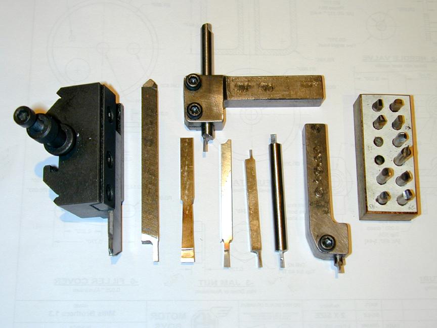
The other tool is the GHT designed 1/4" HSS holder mentioned earlier. It holds the tool "straight" with no back rake. In use, it is normally mounted inverted--as should be obvious--though it can be mounted this way up to support a tool used to "trepan" circular grooves into the face of a job. The big advantage of the tool in this case is the ability to rotate the tool so it assumes the essential tangential position in the groove it is cutting.
The other square tooling in the right hand photo shows various combination parting/fin cutting tools withe the exception of the really broad one second from the left. This is actually a multy-throw crank turning tool. And just to show that I'm still human, notice the broken off tool tip on the 3/16" square tool in the middle. I can't precisely remember the circumstances, but I do recall thinking to myself that whatever I was about to try to do with that tool was not a great idea. What can I say? Trust your instincts!
![]()

This page designed to look best when using anything but IE!
Please submit all questions and comments to
[email protected]
Copyright (c) Ronald A Chernich, 2004. All rights reserved worldwide.