How To Stop Your Comp Screw Wandering
Created: January, 2013
Click on photographs to view in more detail

Introduction
Operators of model diesel engines are all too aware that carefully setting the compression adjustment screw is no guarantee that it is going to stay there. Luckily, they will never get tighter. Instead they tend to back off, reducing compression, power and "song". There are remedies to the problem which can be applied at two levels: treating the symptom, and treating the cause. Obviously the latter is preferable, but sadly, there are times both are required. In this How To..., we'll look at the causes, some cures, and some remedies.
Causes
In the most common design used for variable compression diesels, the contra-piston (CP for short) is a simple press-fit in the top of the cylinder. A fine thread screw in the center of the cylinder head or jacket bears on the top side of the CP. Turning the screw clockwise forces the CP down, increasing compression. Turning the other way creates a gap, so if sufficient pressure can be made to exist within the cylinder, the CP will snap up until restrained by the screw. In a running engine, this is virtually instantaneous. There are exceptions to just about everything I've said here, but we'll cover those later.
The root of the problem hides under the CP. It's the bang-bang-bang of the mixture exploding rather than burning on each engine cycle. Yes, there is some flame-front propagation going on, but a compression ignition engine is basically a violent beast compared to a glow, or spark ignition model engine. This means higher vibration impulses which are trying to force the CP up while they are actively pushing the piston down. Vibration can make the comp screw turn on its helix as the latter is generally well oiled, and especially if the screw thread is a loose fit.
Another factor which can exacerbate the unscrewing tendency is a "point contact" between the comp screw tip and the CP surface, especially if it is off center with the screw axis. This can easily happen in many ways. The most common causes is a "pip" produced by machining, either on the end of the comp screw, or in center of the CP, or both! A rough or poorly faced comp screw tip is another, as is a drilled or poorly faced top surface to the CP itself.
Remedies
Before we look at ways to stop the problem occuring, we'll look at some prophylactic remedies.
 Comp locking lever |
 Friction spring bar |
 Hidden friction slug |
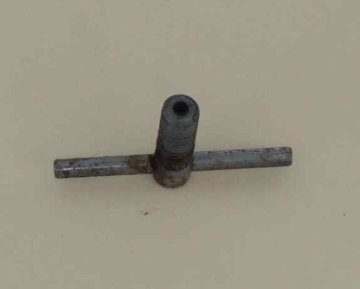
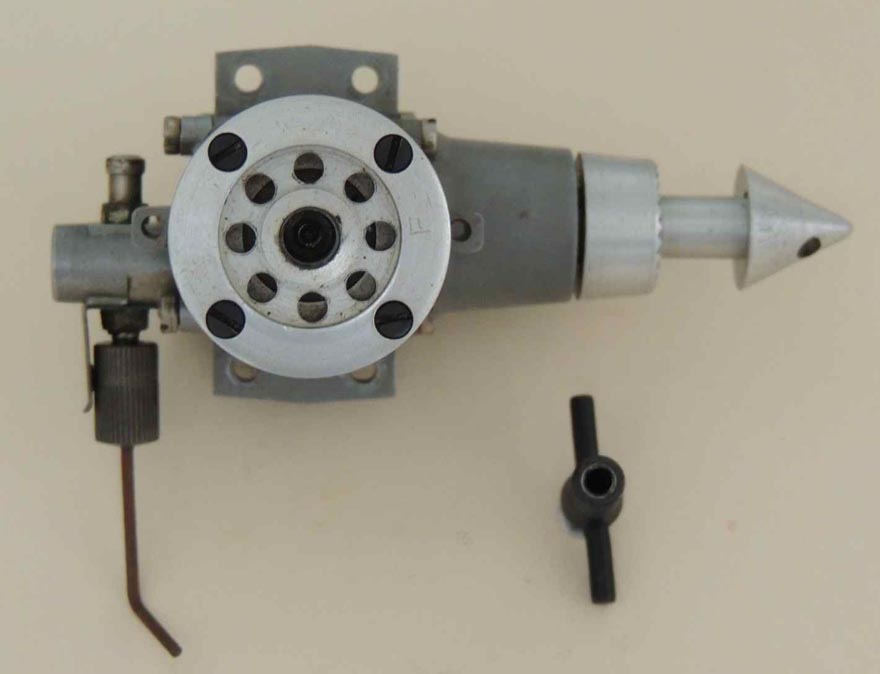
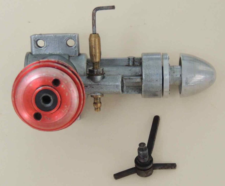
Comp Locking Lever. This is the simplest and most effective solution. The one seen here was standard equipment with early Taipan diesels, supplied to address a chronic problem. Taipan designer and manufacturer, Gordon Burford, knew exactly what caused the problem and how it could be minimized, but could not apply the cure without driving the price through the roof. The easy solution was this stamped aluminum lever, tapped for the comp screw. The downside to the thing is its tendency when loose to vibrate down while you're trying to adjust the compression and lock before you're done. Nevertheless, if you have a problem engine, this is the quickest, easiest, and least invasive solution.
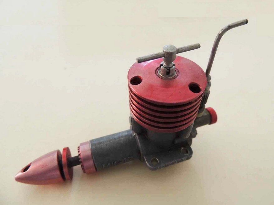
Friction Spring Bar. Gordon's next solution first appeared on his 2cc Tyro and was later applied to the 2.5cc TBR diesel seen in the picture. It's a piece of piano wire bent so that the two end legs poke into two holes drilled in the head. It applies a side force to the compression screw, resulting in enough friction to prevent it shifting. The bar can be pulled up by unscrewing, but works well after initial adjustment. The downside is drilling those holes, not the sort of thing you want to do in a vintage engine.
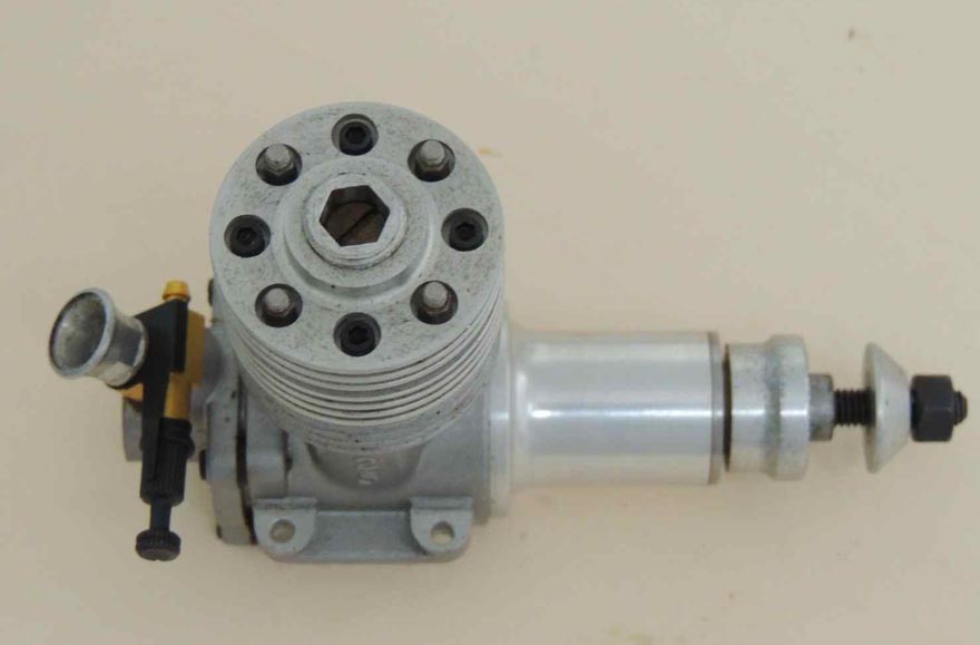
The Hidden Friction Slug. Guess what? Gordon Burford again, this time on his CIE replica. Notice the dark spot between the top fins, radial with the compression screw? There is a hole drilled all the way through to the center, tapped for an Allen head grub screw. This presses a piece of nylon rod (weed-eater material) against the screw thread, again providing friction to combat movement. Tighten the grub screw for more friction. Another effective solution, relatively unobtrusive, but time consuming to implement. Than again, Gordon's replicas were not mass produced and buyers were prepared to pay a premium.

Some manufacturers resorted to a coil spring between cylinder head and the compression screw, often bearing against the tommy-bar. This is a poor solution and, depending on which way the spring is wound, adjusting the compression can tend to tighten up the spring coils, as well as compress them. The stored torque and tension has been known to actually help the compression screw unwind! This is not to say the scheme can't be made to work effectively. The one-turn, flat wire spring on the FROG 180 seen here is not unattractive and the closed ends resist torque effects, but it usually looks ugly and takes more effort to get right than the alternatives.
Having looked at ways we can cure an existing condition, let's see how to prevent the problem in the first place.
Preventions
There's not a lot we can do about the violence of combustion and the resulting shocks to the system (although OK tried, as we'll see later). But as an engine builder rather than owner, there are a number of things you can do to obviate the need for a cure. Below we see two commercial jobs susceptible to slacking off during running.
 Point Contact (1) |
 Point Contact (2) |
As noted in Causes, point contact between compression screw and CP will promote wandering. The first example (left) shows a slight pip in the center of the CP, left by machining. The tip of the compression screw also exhibits a non-flat surface from manufacture. In the second example, the center of the CP has been drilled leaving a conical depression. The tip of the screw has been approximated to the same shape, but given manufacturing tolerances, it is highly unlikely the two matched, or were concentric. The result in both cases is a small point of contact between screw and CP, offset from the screw axis, resulting in a tendency of the screw to turn under vibration.
 Center drilled tip |
 Center drilled tip |
 Floating pad |
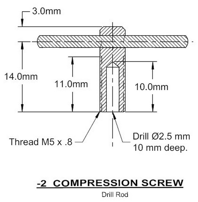
The first photo (left) shows how drilling out the tip of your compression screw can eliminate the center of the screw as a point contact source, and to a degree, bridge a slight pip in the CP center. The center photo shows this practice carried out by ETA Instruments on their 2.5cc team race diesel. The plan extract (the Owen Mate 2cc DIT diesel) shows a simple blind hole. I now prefer to do this with a #0 center drill (aka "Slocumbe" drill). The 60° flutes allow you to gradually widen the hole diameter until just a narrow band of tip remains.
The photo on the right illustrates another approach, as applied to my Sugden Special team race engine. The CP center has been carefully machined so no central pip is present (you should always aim for this state in any case). The tip of the compression screw has been drilled as before, but this time a brass pad with a short stem is added to the screw. The fit is rather loose, allowing the pad to float a bit and press flatly against the CP. For a bit of extra effort required during construction, this works surprisingly well.
In all cases, you need to aim for a firm fit between the compression screw and its thread. Tap the head first, then open out your threading die to cut an over-size male thread. Gradually close the die, testing the fit until it is firm, but not tight. If you make it too tight, not only will it be hard to adjust, it's likely to gaul the aluminum thread, resulting is swift wear to a loose fit!
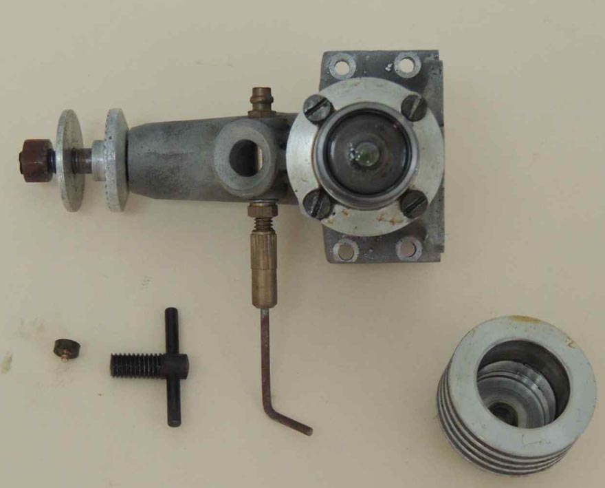
Aluminum is not the best material for a working thread, so some engine makers go to the added effort of fitting a steel, or brass plug, tapped for the firm fitting compression screw. This can be pressed, glued, or screwed into the aluminum head with a flange on the bottom to prevent jacking action of the compression screw pushing it out of the head. The example seen here shows such a device in blued steel, fitted to a Karl Zeiss Jenna 1cc diesel. Very neat, and very long wearing. Sadly, they've also machined away the diameter of the compression screw end to a small, solid tip, then fitted a massive pressed steel comp screw locking lever to cure the problem they created.
The Rissian made Mk 17 went one better. Their plated steel insert, as seen in this photograph, extends above the cooling jacket and has been quadrilateral splits, similar to some types of self-locking machine nuts, in order to provide additional grip on the compression screw.
Modern team race diesels arrived at a different solution, typified by the experimental Gordon Burford 2.46cc engine seen here: the push-pull CP. Details vary, but in general, a large diameter screw is fixed to the CP in a way that allows the screw to rotate while the CP does not. Because they are a unit, the screw both pushes and pulls the CP, providing a very definite adjustment, assisted by a fine thread on the large diameter screw. The size, fine thread, and a close fit means that friction is sufficient to prevent unwanted movement, although some use the nylon pressure slug for insurance.
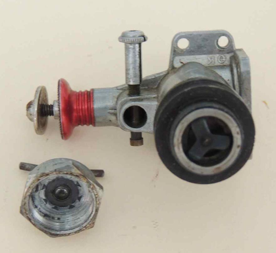
During their brief dalliance with diesels, US manufacturer, Herkimer Tools (aka, "OK"), came up with a unique solution. The compression screw pressed down on the CP rim through a bronze, three legged "spider". The intent was to provide a degree of cushioning between the CP and the adjusting screw. Like McCoy, OK used an aluminum CP, sealed by a high-temperature O-Ring. This works fine, but lacking the firmness of a tight press fit cast iron CP, all of the pressure is going to find its way to the compression screw thread. OK made additional claims for their invention and covered it with US Patent 2,733,694 to protect their "world's first shock-proof diesels". For more details about this engine, see our OK Diesels page.
Beyond Scope

Before leaving the topic, we should mention some odd-balls. First, we have the Speed Demon Diesel where turning the compression screw clockwise reduces the compression because it is raising the cylinder liner (which has a closed top end). This also changes the engine timing, but works quite well, regardless. Second are the engines which use the cooling muff itself to adjust the compression setting, such as the ED "Penny-Slot" pictured here, and those using an eccentric crankshaft bearing to effectively raise or lower the crankshaft axis and hence the piston position at TDC. Examples include the Scottish Clan and one of David Andersen's early diesels.
Conclusion
The problem of the wandering compression screw is a common one in mass produced sport diesel (compression ignition) engines. It is caused by the high impulse induced vibration and wide manufacturing tolerances causing point contact between the compression adjusting screw and the contra-piston, frequently exacerbated by a loose and/or coarse thread on the screw. The simplest fix is a locking lever, although this can complicate handling and place the fingers fiddling with it in dangerously close proximity to the flesh-slicing disc at the front of the engine. Model engine makers can take simple steps to prevent point contact, and ensure the thread is fine, and firm. Other solutions and avoidances exist. Some we've examined here. There are others, but please, please avoid the big, ugly hex nut solution!
![]()

This page designed to look best when using anything but IE!
Please submit all questions and comments to
[email protected]
Copyright (c) Ronald A Chernich, 2004. All rights reserved worldwide.