How To Work With Cast Pistons
![]()
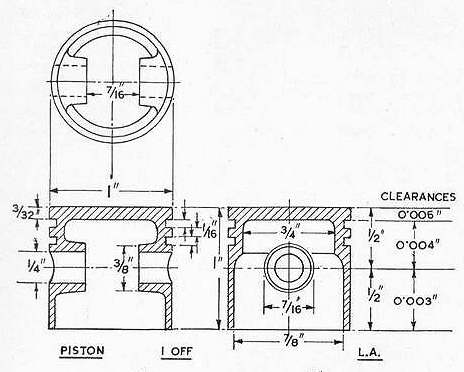
This tip came about as a direct result of a set-up problem I encountered while working on the ETW Whippet Project. The cast piston is cored to make it as light as possible. But the 1/4" diameter wrist pin needs a good bearing area, so 3/8" diameter bosses are cast on the inside. The problem was determining the best way to mount the piston to drill and ream for the wrist pin so that it would be centered in the bosses while located transverse to the piston axis, and on the piston diameter plane. The Whippet text said that the pistons were cast with a spigot. This would have made things easy, but my modern casting was not. What to do? I played with various schemes in my head before deciding to consult other ETW texts for a clue. The answer was found in the Phoenix article. It's quite simple, effective, and worth documenting.
The drawing at the top of the page shows the piston design. This tip deals only with the steps required to drill and ream for the wrist pin. To finish the piston, it will be mounted on a true running mandrel, similar the this one that uses the piston skirt and wrist pin to both hold and align it for final skimming to the bore and cutting the ring groves.
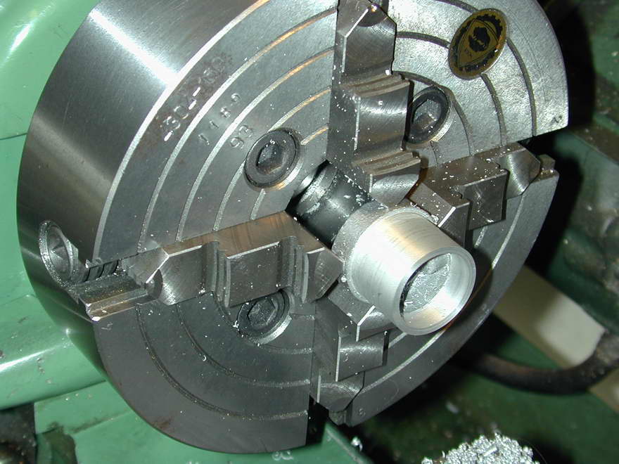 The first step is to mount the piston in the four-jaw independent chuck so that the ID runs as true as possible, or at least with any "oval-ity" equally disposed around the central axis. The ID is then cleaned up down to the bosses and the OD turned to a comfortable oversize diameter to allow for later skimming. Finally, the length of the part is reduced to the finished dimension as measured to the top of the bosses, allowing for their diameter. If they are not even in location (and these weren't), split the difference so the wrist pin will be located a little off in both, not right in one and a lot off in the other!
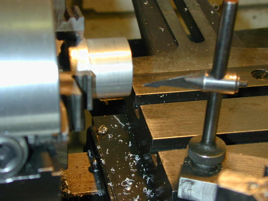 Before removing it from the chuck, it is rotated so that the bosses are horizontal and a scribing block used to scratch center lines along both sides of the piston. In this photo, I'm using a GHT lathe center height gauge, the first thing I actually made after buying the lathe. GHT cunningly designed it so that it so that it not only provides a setting datum for tooling, but can be used as a scriber for just such tasks as this. As the piston is oversize at this stage, scribing lines in it does no harm. This done, the position of the wristpin is measured from the skirt and center popped on one of the scribed lines.
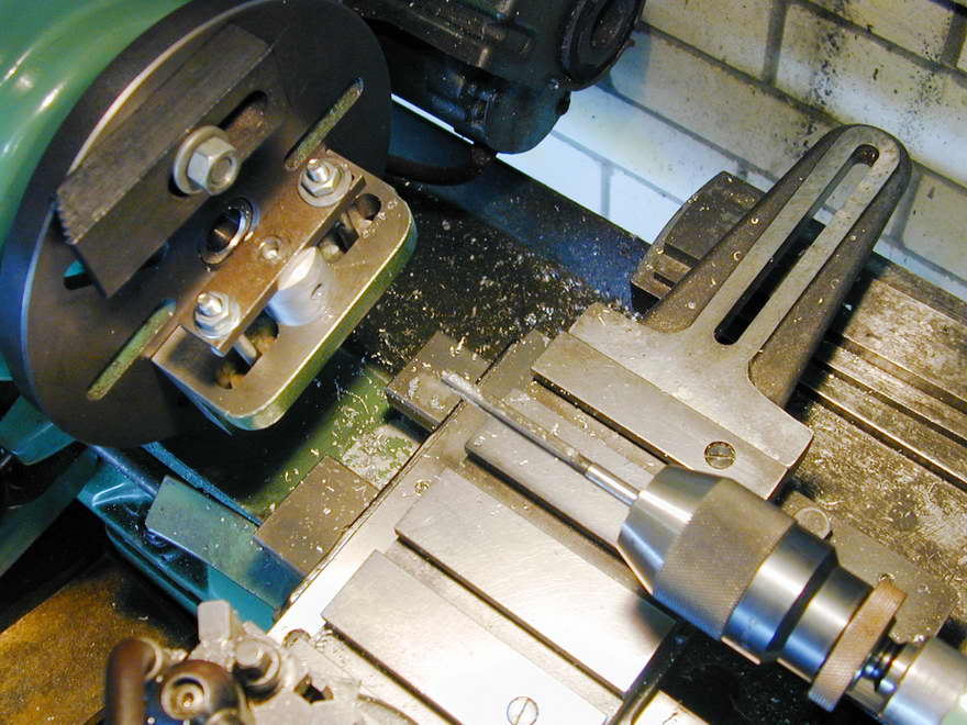
 The next step requires a good angle plate with a line scribed across it that is at right angles to the mounting face. The idea is that the piston will be aligned on the angle plate so that the opposed scribe lines are aligned with the line scribed on the plate. The result is that the piston must now be perfectly positioned so that a hole drilled through the center pop mark will be on the diameter, and pass neatly through the (invisible) bosses. This photo shows the center popped wrist pin locations on the scribed line, and the marked up angle plate (single, fine lines only please, no tram tracks!)
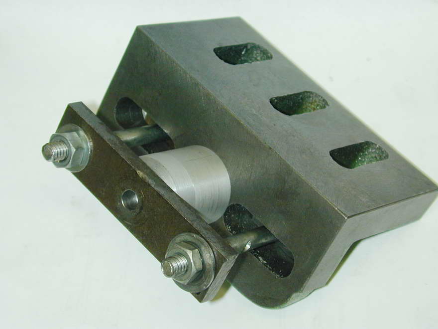 A flat bar and a couple of long bolts have been used to clamp the piston into position. Prior to this, the piston had been held lightly in a three-jaw chuck to skim the crown flat and remove the as-cast area where it had been gripped in the four-jaw chuck. Like the machined outside diameter, a generous allowance for final skimming has been left on the crown.
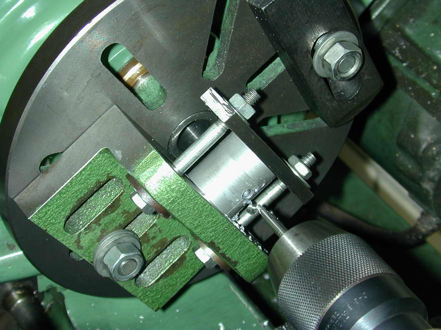
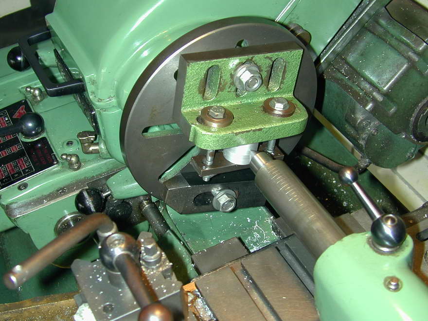 The plate can now be attached to a lathe faceplate using the center popped wrist pin location for final alignment. This photo shows the rough position being set by resting a dead center in the center pop while the mounting bolt is tightened, leaving the plate loose enough to be tapped into final the position.
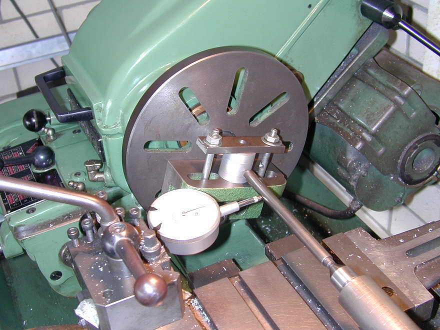 The "dead center in the punch mark" trick will get the work close, but alignment should be finalized using a wobbler (another GHT design) and a DTI. As the angle plate represents a considerable out of balance weight, something from the mill clamping kit will be attached opposite it before the next operation.
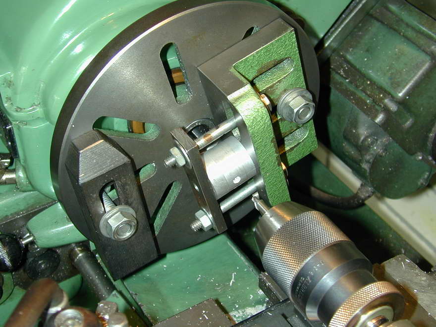 With the dot running true, the wrist pin hole is center drilled, then drilled through 1/64" under size for final reaming. Reamers like to cut, and 0.008" is a happy amount for all concerned. The center drilled start is now drilled until the drill breaks through to the core.
 At this point, we could continue on, but there is no guarantee that the face of the boss the drill next meets won't draw it off center, so the center drill is used again to start the hole into the unseen boss face through the hole just drilled.
 With the hole drilled, it's a good idea to finish the job with a venerable and slightly worn 1/4" reamer, if you have one. A nice, new, sharp reamer will be used on the conrod little end. The reason for using an old reamer is so the wrist pin will be tighter in the piston than the conrod. The conrod will have an oil hole in the little end that will be of no use if the pin decides it would rather rotate in the piston!
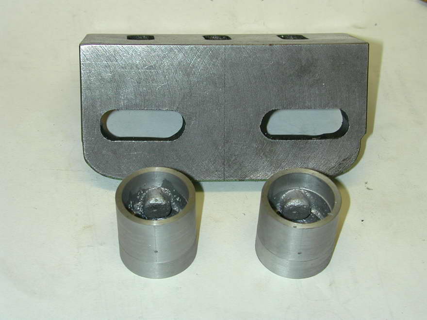
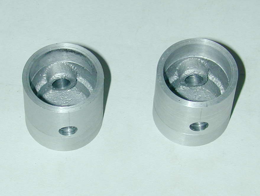 And here is the end result. Two pistons with the wrist pin holes reamed as central in their internal bosses as the coring will allow. All accomplished "blind", as it were. Thinking about it, this technique will work for aligning any circular, or even irregular shaped parts that have received some lathe work allowing opposing axis marks to be scribed while still mounted. Naturally, the chuck must remain steady as the marks are scribed, but the friction provided by the normal headstock drive train will be sufficient for that if you are careful.
![]()

This page designed to look best when using anything but IE!
Please submit all questions and comments to
[email protected]
Copyright (c) Ronald A Chernich, 2007. All rights reserved worldwide.