Cam Grinding Machines
") |
 using Sherline parts") |
 based on the Gene Switzer design from SIC") |
Click on photographs to view in more detail
Hover for a description
Of all the various ways to form harmonic cams for model four-stroke engines, the method with the greatest potential for accuracy and repeatability is to use a machine that grinds the cam from a scaled up master cam profile[1]. The advantages include:
- If the master cam is large, forming it to an accurate profile is comparitively easy
- As the finished cam is a scaled down replica of the master cam, any imperfections in the master are also reduced
- All ground cams should be identical in profile and size, with a very fine, smooth finish—provided any grinding wheel wear is accounted for
- The method permits the cam blank to be hardened before grinding to shape
- Depending on the design of the machine, precise phasing of the cam lobes on a one-piece shaft is simplified compared to other methods.
Several designs for cam grinding machines have appeared in model engineering magazines (see References). In many cases, the machines have been assembled from whatever was lying around that would do the job for the designer, so a plans-builder is left with some need to improvise. Generally, this is not a problem since any model engineer who decides to make a cam grinding machine is somewhat beyond the beginner phase. This is not something I've done, so take the information on this page with a grain of salt! But I have examined a couple of physical examples that did the job, and done some reading on published designs to provide the bare basics of cam grinder layout and options.
Full Size Commercial Practice

Commercial Cam Grinding Machines are adaptations of cylinderical grinding machines. The shafts they form are usually induction hardened before grinding, so distortion ooccurs and cylinderical grinding of the journals is required to being them into line. The schematic here shows a commom pattern employed on many commercial cam grinders. The master and generated cam are rigidly coupled on a common axis. This shaft is pivoted on rocking arm links such that the master cam contacts a roller follower, while the generated cam is in contact with the grinding wheel. It should be noted that the center lines of follower and grinding wheel do not coincide. The grinding wheel can be moved longitudinally to other cam stations and the master cam rotated to provide the desired phasing. Although simple, my research has not found any model cam shaft grinders made to this pattern.
Model Engine Sized Cam Grinders
")
The most common published design has three parallel shafts. Two are mechanically inter-linked so that they can be rotated in the same direction in a 1:1 ratio. This connection can be any non-slip means and I've seen chains, gears, and toothed drive belts used. The master cam is positionable along the first. The second is the generated cam, or rather a carrier for it. The grinding wheel is mounted on a rocking arm that pivots on the third. It too can be repositioned and locked over the cam locations. A follower attached the arm rests on the master cam. The moment arms provide the scale-down factor from master to generated cams. The inter-connected shafts need to be rotated at a relatively slow but steady rate. I've seen hand-cranked machines and various automated drives provided by windscreen wiper motors, electric car window drives, messes of gears, and more recently, stepper motors ratted from old printers. The picture here shows a conceptual layout along the lines described.
 displayed at GEARS '05.")
Positioning and pivoting the grinding wheel can be accomplished by a sleeve the slides on a rod which must be perfectly parallel to the other two shafts. Some means also must be provided to dress the wheel in situ and to adjust the height of the wheel from the work, preferably with some calibrated means to adjust it. In this photo of a machine designed by Eugene Croll taken at the 2005 GEARS exhibition, the wheel head is shown rocked back providing access to the shaft for inspection and measurement.
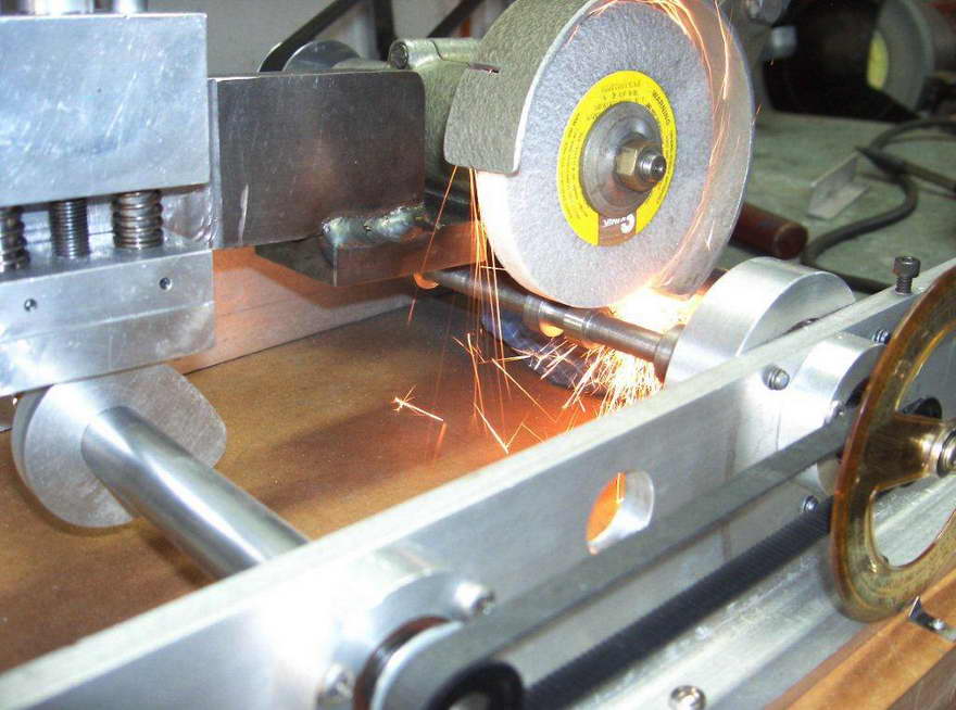
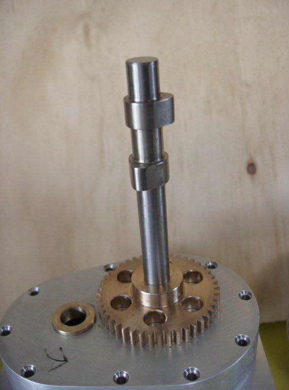
The way in which the cam shaft blank is held varies as it needs to be held rigidly and truely, while providing for various shaft lengths and diameters, and permit them to be removed and without drama. A lathe-like "between centers" approach with drive dog coupling works well for this. Grinding is a slow process and wheel wear, "loading-up" and the consequent need for dressing should be minimised. Hence it's not a bad idea to rough the cams out by milling before grinding.
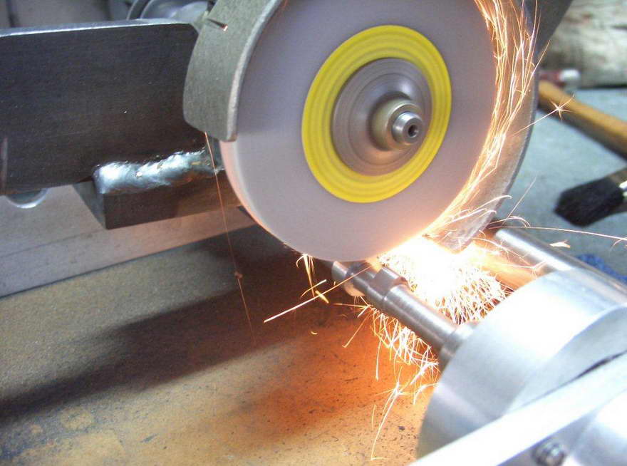
One small but important detail is the follower that is attached to the wheel head and rests on the master cam. The one pictured here is flat. For this type of machine, it should theoretically have a radius equal to that of the grinding wheel times the reduction factor. If the reduction factor is large (say factor 4 or more) a flat follower as seen here on Chris Dunn's machine will be fine. But if the ratio of master cam to finished cam is small, a flat follower will not reproduce the master cam shape. At the extreme where the ratio is 1:1 like the machine designed by Jerry Kieffer at the head of this page that appeared in HSM [2], a follower with approximately the wheel radius is very important. Obviously wheel wear and dressing is a factor, but you need to start out right.
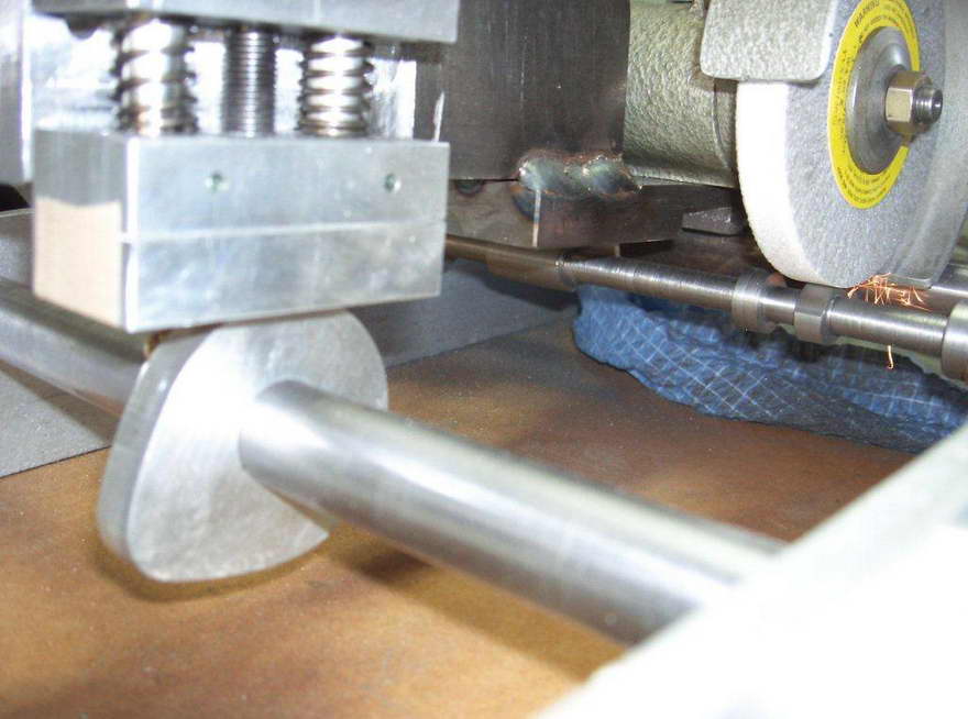
Some means to set the distance between the wheel and the work must be provided. Chris has used a simple bolt that pulls the pivoting arm closer to the follower against spring tension. This will work fine and even a coarse thread will provide fine adjustment. It does not need to be calibrated, although some designs incorporate a DTI to assist repeatability on multiple lobe cams.
 Grinding wheels will wear and may "load up" with metal particles requiring them to be dressed to expose new cutting facets, and to restore a uniform, flat surface. More sophisticated devices will incorporate a coolant and flushing agent at the work point to prolong life and improve the surface finish. Some cams are purposly ground at an angle to induce tappet rotation and reduce wear. This can be done by dressing the wheel at a small angle.
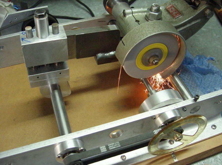
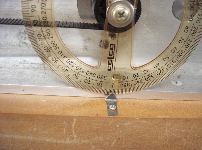 Then there's small details like some means of accurately determining the angle between the cam shaft and master cam when grinding multiple lobes on the shaft. The builder of this machine solved the problem by fitting as a drawing protractor to the work shaft with a pointer on the base plate.
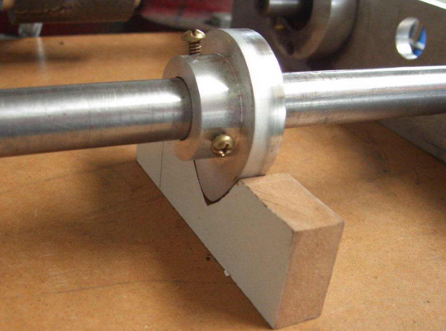
The master cam is indexed on its shaft with set screws and a simple V block is used to orient the cam. It all sounds a bit daunting, but as seen in the photos sent in by Chris Dunn (Australia) of his machine, with some ingenuity and a well stocked scrap box, you can produce excellent results.
 Chris has adapted a tool-post grinder to the task with the shafts riding between a couple of pieces of aluminium angle screwed to particle board. What could be simpler? So consult the references, look in your scrap box, and produce your own mechanical monster to puzzle your heirs with.
References
![]()

This page designed to look best when using anything but IE!
Please submit all questions and comments to
[email protected]