Building the W-Hobby Superba 2220 F1A (A2) Kit
![]()
Last update: Feb 24, 2002.
Click on a photo to view it enlarged.
 Background
The Kit
Fabricating the Spars
D-box Construction
Wing Construction
Fuselage
Fin Runner and Tail Fittings
Covering and Finishing
Flying and Trimming (1)
Flying and Trimming (2)
Conclusion
Background
The Kit
Fabricating the Spars
D-box Construction
Wing Construction
Fuselage
Fin Runner and Tail Fittings
Covering and Finishing
Flying and Trimming (1)
Flying and Trimming (2)
Conclusion
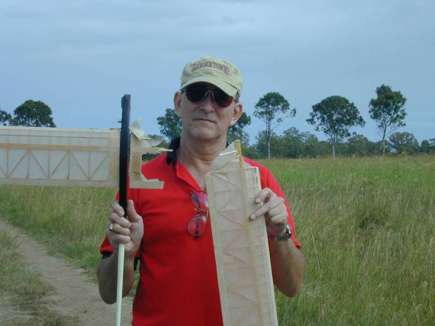
It's been pointed out to me by various club members that I appear to be making a habit of towing the wings off A1's and A2's during contests; especially if it looks like I might actually place. Faced with the 2002 contest season and the need to rebuild an inner wing panel of my John Cooper inspired F1A for the second time, I decided that a better answer might lie in a model that an old geezer like me can't possibly overstress: hi-tech kevlar and carbon being the obvious candidate.
A bit of browsing the 'net led me to the W Hobby site, a Lithuanian company that specializes in F1A, B, C, E and J using the most uptodate "hi-tech" construction techniques for completed RTF models, kits and component. Now I have a philosophical objection to RTF at the competition level, although the price of these is quite reasonable, if you're being paid in US dollars instead of South Pacific pesos. But the kits looked good, so after checking the certificate of the company that collects your credit card details on their behalf, I took the plunge and ordered a pair of F1A kits: their "medium-tech" model, the Sija--circle tow and zoom, carbon tube spar and caps, no D-box, and the Superba 2220--a full carbon/kevlar D-box, circle tow, zoom launch "bunter".
The plan was to build the Sija to get experience with carbon building techniques, as a circle tow trainer, followed by the Superba as the out-and-out competition model. Unfortunately, delays in delivery of the Sija have reversed this brilliant plan, so with the first competition day rushing towards me, the Superba had to be built first and fast. I must point out that communication from W Hobby has been first class with emails keeping me informed of hold-ups and delivery etc.
This short article (like I can ever write a "short" anything) is intended to highlight some aspects of this type of construction to those doing it for the first time and wanting to learn from all the mistakes I made in doing it for the first time, or for those wondering if all this hi-tech construction is really worth it.
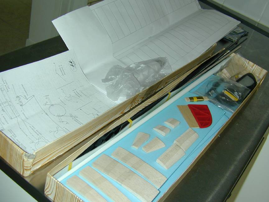
As received, the Superba 2220 is a complete dry kit to which you will only have to add adhesives, dope and paint. The wood selection is just what I would have picked and finished exactly to shape. The hardware package contains everything, including the appropriate control lines; even the turbulator thread and bonus mystery parts. The D-box shells (2-layer carbon for the wing, kevlar for the stab) are beautifully formed and finished with a white, outer gell-coat to limit heat absorbtion under the covering. For a complete list of the kit contents, visit W Hobby's Superba page.
The instructions accompanying the kit are minimal. This is as one might expect, since a modeller building this sort of model can reasonably be expected to be both experienced and resourceful.
They comprise one 2-sided sheet giving very basic wing constructions hints, another sheet giving flying and trimming hints (for setting the bunt and zoom times), 2 sheets showing the timer and actuation line set-ups (that almost, but not quite co-respond to the current revisions to the mechanisms) and a final sheet covering basic fuselage pod assembly. On checking my kit contents, I found 2 small hardware items missing. An email to Vidas Nikolajevas at W Hobby got a quick response: they would be packed in with the Sija, when it got shipped.
The first step is to assemble the spars. These are a carbon/balsa sandwich, wrapped with kevlar thread. The balsa webs have the grain running spanwise and are ready tapered (top-bottom) from straight, hard balsa. To these must be epoxied the tapered (fore-aft) carbon caps. Before beginning, the caps are lightly sanded to remove any residual release agent that might prevent the epoxy from sticking to the carbon. Following sanding, they are rubbed with acetone to remove the dust and finger oils. After this step, avoid touching the surface that will receive the glue.
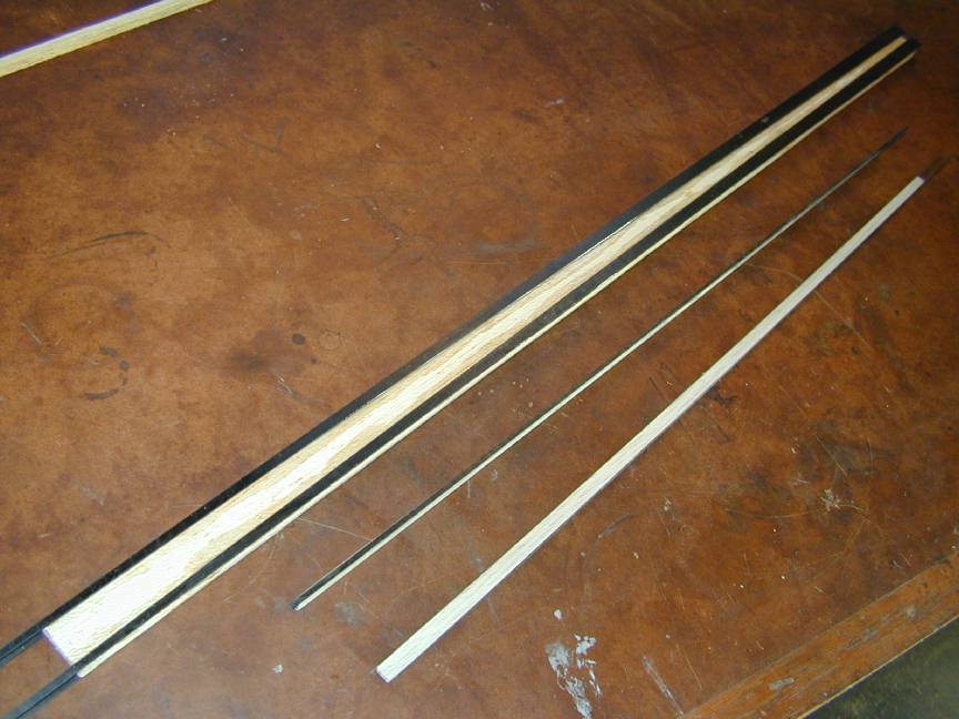
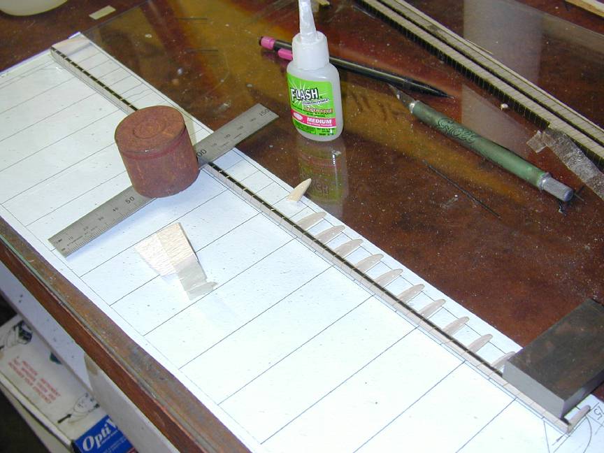
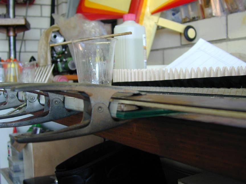
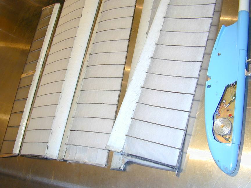
To laminate the spars, I used 30 minute epoxy applied to the balsa web block using my favorite workshop tool: old business cards. This epoxy gave enough pot-life to do both sides at once before weighting down the assembly between flat surfaces to cure. To achieve the correct allignment of the top and bottom caps, I lined them up with the outside edges of the web block. These should be sanded flat first--I didn't and later regretted it. Be very carefull when applying the weights that the caps don't shift and ruin the top-bottom registration. The photo here shows the inner spar caps glued to their shear-web block, an outer spar after sawing from its block, and the stabilizer spar: 1/16" thick which comes with its caps already attached saving you from a difficult job. Note how the distance between the spar caps makes the sandwich "stable" on the bench and simplifies weighting down during curing.
After a good 12 hours under weights, the individual spars are sawed close to the cap size, then sanded to final taper. When black dust starts to appear, stop sanding! Next, the spars need to be spiral wrapped with the very fine (but very strong!) kevlar thread supplied. Before doing this, I lightly sanded the edges of the carbon caps to remove the knife-edge that might cut through the thread fibers. The approximate winding pitch is shown on the instruction sheet. In the wing joiner area, 0.5mm; for the remainder of the inner panel spars: 2-3mm, while the outer panels are wrapped at a pitch of 4-5mm. However, a note says this is for F1B (Wakefield) spars which these instruction sheet seems to have originally been written for. I assumed the F1A spars would be the same. I was also concerned that the little spool of kevlar thread may not be enough, so I tended towards the wider spacing. I need not have worried: there was plenty left over.
Vidas at W Hobby has looked very carefully at my photos and added this comment in order to keep me awake at nights: While looking at your photos I found one rude mistake in your construction: spars are wrapped with too little kevlar. Root spars should have very close wrapping (0.5mm pitch in root, 1mm near dihedral and 1.5-2 mm on the wingtip). Carbon spars will separate on high load/tension if they are not wrapped enough. I have experienced that myself many years ago, and now looking at your photos I suspect that this might happen to you too... There is no way to fix it now, so just try to be a little more careful when accelerating/launching the model.
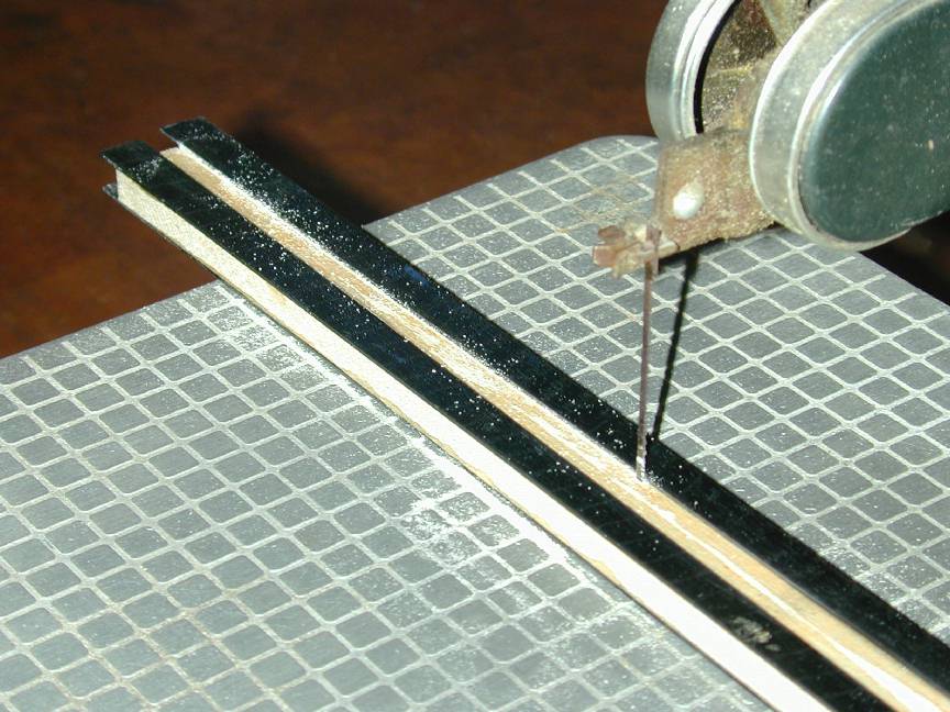
The instructions would have you complete the wings, then epoxy in the wing joining tube. I didn't like this for a number of reasons, chief being I was afraid that if I made the cut-out for the tube, the wrapping process would collapse the spar in that area, destroying the profile. If the gap were filled in with a temporary piece, it would be difficult later to get it out without damaging the kevlar binding. Alternately, drilling for the tube after the wing was built would be extremely difficult and potentially disasterous requiring the drill to be hand held and guided. The joiner tube (ready made from kevlar/epoxy around the fully hardened 6mm wing joiner) required a 6.5mm slot. This is close to 1/4" so I used a 1/4" ball-end slot drill in my mill to cut a slot just deep enough to take the tube and parallel to one cap, arbitrarily selected as "top". By not cutting full depth, the remaining web would hopefully retain the correct spar height during wrapping. Next I aligned the spar "tops" against a 1m straight edge and epoxied in the joiner tubes. As the front of the spars are at right angles to the root, I should get the perfect line-up, right?
Well, it both worked, and didn't. The line-up has given me a flat top wing surface and any minor skew was corrected by sanding the root ribs to mate with the fuselage pod sides. What did not exactly work was avoiding "crushing" of the spar in the joiner area during wrapping. It amazed me: I placed the joiner in the tube as I wrapped the spar in that area and I wrapped firmly, but not tight. Net result: the joiner tube went from a close sliding fit to a firm push fit that got worse with time! By the time the wings were finished, it was just too damn tight to be usable and no way would the wing wriggler be able to activate smoothly. This would probably have been avoided by following the sequence in the instructions, but I still think the spar would have collapsed more in the area of the joiner. As an engine builder, I was able to fix the problem by placing the joiner in my lathe and applying a Sunen external home to it to remove a thou or so until I had a firm "popping" fit. This took a very long time as that joiner is very hard! Obviously, this cure would not be available to most modellers, so be on your guard for this problem.
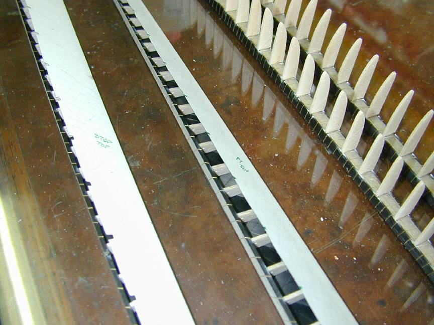
Lesson learned? The joiner and tube should go in last, but some way of maintaining the spar profile needs to be worked out (I still shudder at the thought of trying to drill that hole in a completed wing). I'm calling this Big Mistake #1, though I still don't have a better plan for next time. I also managed to induce a spiral warp into one of the outer spars during the thread wrapping process. The instructions say specifically not to glue the thread to the spar except where ribs and D-box attach. I assume this makes the spars more springy and flexable. It also allowed me to correct the fault by a bit of carefull twisting and accurate jigging during D-box assembly--but better if it can be avoided in the first place. For an idea of the kevlar wrapping, look closely at the inner spars visible in the background of the outer wing panel construction photos.
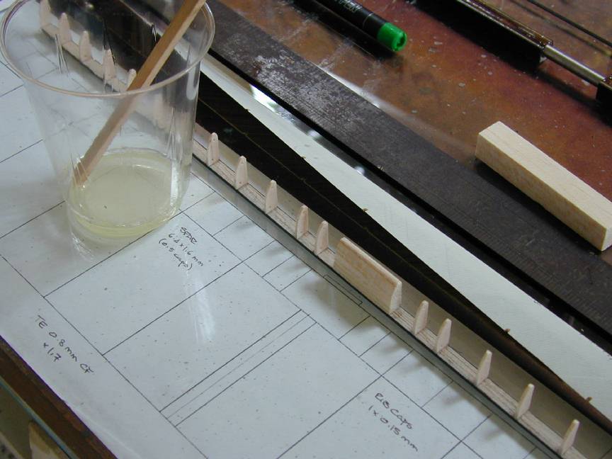
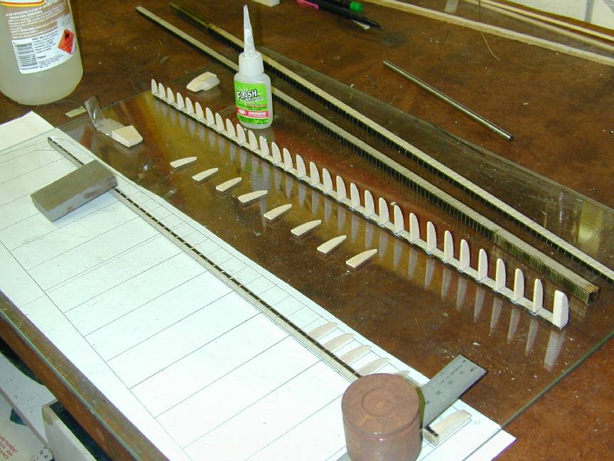
This begins with gluing the half-ribs to the spar with mediun viscosity cyno. All the ribs supplied in the kit were an excellent fit and although the instruction sheet warned some trimming would be needed to achieve the correct length, I did not find this to be so. To gain experience with the process, I decided to build the stabilizer first. The picture here shows the forward ribs ready for the D-box. The plan is under a thick pane of glass. This is a good working surface: flat and reasonably cyno resistant (but keep the bottle of acetone handy for spills etc). Note the kevlar LE shell in the background of this shot: notches have been cut at each rear rib position, top and bottom to allow the carbon rib caps to be glued to the spar caps rather than the D-box shell as some constructions advocate. This idea comes from W Hobby's instructions and makes a lot of sense to me. The hard part is cleaning the squeezed out epoxy from these notches after it has cured. I used a little flat needle file, being careful where kevlar thread corresponded with a notch on the wing (no kevlar binding was suggested for the stab).
These shots show the nose ribs being applied to the outer main wing spars. The dihedral rib is thick and so it is glued first and used to align the spar for positioning of the remainder of the ribs. A word on the plan supplied: it is no more than a basic outline showing rear rib positions with a small "cut-away" area on one outer and inner panel to show the nose rib spacing. To actually glue in these ribs, you really need to extend the main rib lines to the leading edge and draw in the intervening nose ribs. There's no reason why these should not be added to the master plan copy to save you the bother. As both inner and outer D-boxes taper in height and depth, you need to be careful to keep the sandwich-sanded ribs in order. Work with a few at a time, leaving the others stuck to the tape they are supplied wrapped up with until needed.
Note that the apparent misalignment of ribs, spar etc with the plan in these shots is caused by the plan being under the thick sheet of glass; wouldn't want you to think I'm a sloppy builder!
While the stab box went together with 30 minute epoxy (just) a longer pot life was needed for the wings. I opted for a 3 hour variety that gave me 45 minutes (nominal) pot-life. This needs to be smeered to every rib, then the spar caps, so don't underestimate the time this will take! Also remember to give the inside of the D-box a light sand and rub with acetone to make sure all traces of the mould release agent are removed. I forgot on the first outer panel and by the time I remembered it was way too late. I'll worry about that forever--I don't even remember which panel it was, so I'll have to worry about both of them! (call it Big Dumb Mistake #2).
The shells themselves are considerably oversize and must be trimmed, then notched. I used a white grease pencil sharpened to a chisel point to mark the trim line using the spar as a guide (taking care to wipe the spar with acetone to remove unwanted grease pencil residue after). Tin-snips were then used to cut within 2-3mm of the line, followed by a final cut on the line--this is an old aircraft sheet metal trick; it's very difficult to cut into a sheet to a line, but easy to trim off a thin strip to the same line. The shells need to be a perfect fit; you can't sand them down later as that would destroy the kevlar wrapping. Leave them over-length and adjust the position, span-wise of the rib/spar assembly to the best-fit location. In this location, mark the position of each rear rib on the shell with a fine-point, permanent felt marker. Gang up 2 or 3 abrasive cut-off disks on your Dremal Moto-tool, mount it in a vyce, or a jig and then push the shell together, lining up top and bottom edges to cut the rib cap notches. You need to carefully jiggle, bend and twist the shell to get it to clear the tool body, but it can be done if you have two hands free. This why it is essential to have the tool itself firmly stationary--you absolutely cannot do this with the tool hand held. Next sand the insides and wipe with acetone (the level in the bottle is getting lower all the time).
After carefully pushing the epoxy coated fish-bone into the shell to align with the notches, place a length of 3mm square balsa (1/8" for old purists like me) down the middle of the spar, then wrap tightly with masking tape in the middle, then at tips, between the cap notches. It will buldge like crazy either side of the wrapping, but don't worry. The reason for the square strip is so the masking tape will have something to push against and ensure that the nose ribs are rammed well and truly into the point of the shells. I hit on this trick after making my tip boxes and noting that there was a small but noticible gap (bugger!). The strip trick, which I will claim credit for, but which is undoubtably not original, worked perfectly on the more highly stressed inner panels.
Now place the mess on the edge of a flat board (or thick glass pane) and start applying masking tape from board top, over the shell, around the spar and onto the bottom of the board. Pull it down tight. Cover the existing tape at the tips and center first, then work at intervals rather than proceeding from one end to the other to prevent creating a bulge you can't deal with. After you have tape between each pair of notches, use acetone on a paper towel to wipe epoxy from the notches visible on top of the spar. There's nothing you can do about the bottom ones except needle file it out later; even the top ones will need a small clean-up. Finally, I placed a large lump of triangular balsa trailing edge stock on the shell with a metal straight edge on top of that so I could clamp the whole thing firmly, not tightly, along its entire length. Each D-Box was left like this to cure over-night for at least 12 hours.
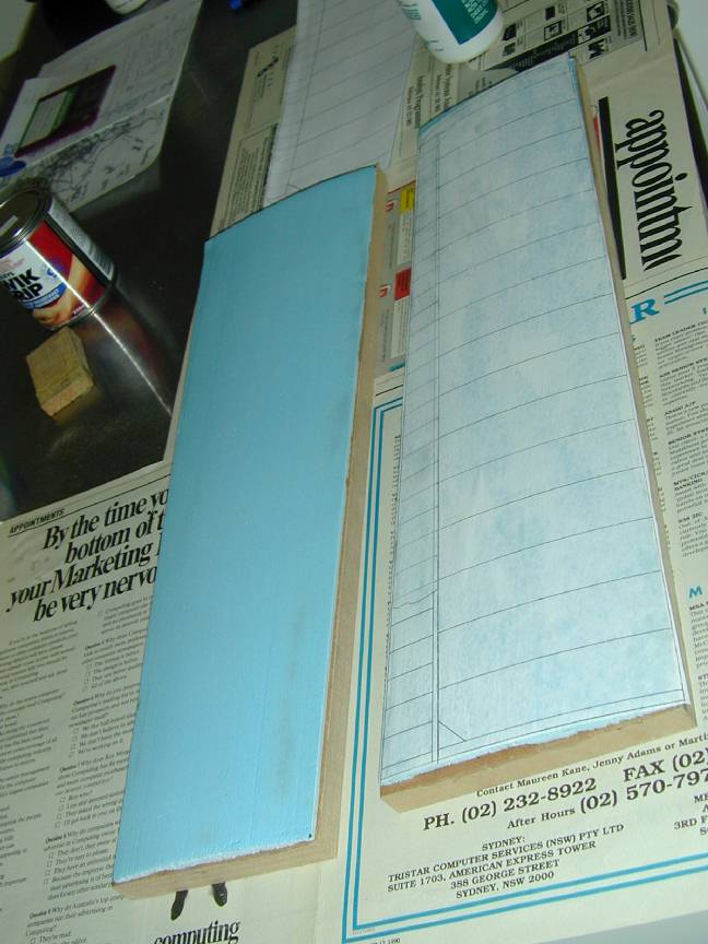
The kit includes convex camber jigs pre-cut from blue foam to match the undercamber of all four wing panels, the stab being flat. These need to be glued to flat backing blocks. Although the instruction sheet says to be carefull to get the warps "per the plan", the plan contained no information about warps at all. Looking at the blue foam, it looked to me like they contained the appropriate wash-outs, so I crossed my fingers and pressed on. The blue foam will be attacked by certain kinds of contact adhesive, so try to use a water-based product. I decided to cut up the wing plans and glue them to the top of the foam jigs with thined PVA. Each jig was then tightly wrapped with cling-wrap to protect the paper from small cyno spills.
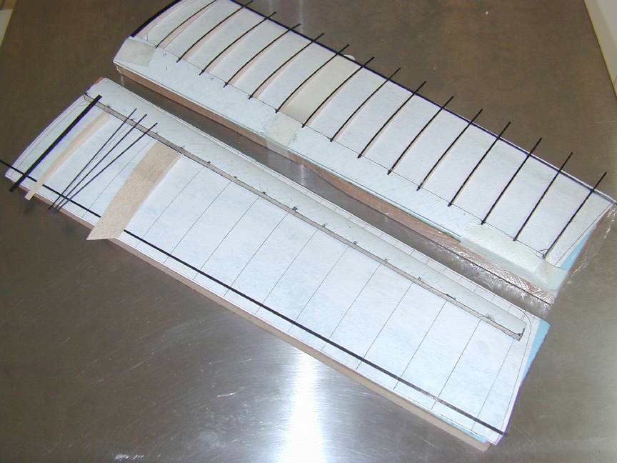
The D-box is secured to the jig with masking tape as shown here and the rear ribs cyno'd to the spar. I placed a thin packing piece (slice of good old business card) under the front of each rib as it went down to allow for the rib cap thickness. Again, be carefull of keeping the tapered ribs in order and double check the height where they meet the spar and the angle to ensure the rib sits easily against the contoured jig. Some rib stacks needed a very minor touch up with fine sandpaper, but overall the fit was expectionally good.
After the ribs are glued to the spar, they need to be trimmed to length. Place a long straight-edge over the wing at the trim point. Follow the chord dimensions given on the plan for root, dihedral break and tip, carefully measuring each rather than depending on the outline. I didn't do this and so managed to end up with one inner panel almost 3mm narrower than the other at the root--Big Unfixable Mistake #3, *sigh*. With the straight edge held in place, use a sharp blade to trim each rib to length, taking care not to cut through the cling-wrap. Now glue the carbon trailing edge to the two end ribs only, making sure it is flat and follows the camber of the jig. Move to the middle and raise that rib above the TE, apply a small amount of cyno, then press it down and the TE forward. Repeat at the 1/4 span ribs, inboard then outboard, followed by 1/8, etc until all ribs are glued. This avoids pushing a mistake along the panel that might happen if you worked from one end to the other.
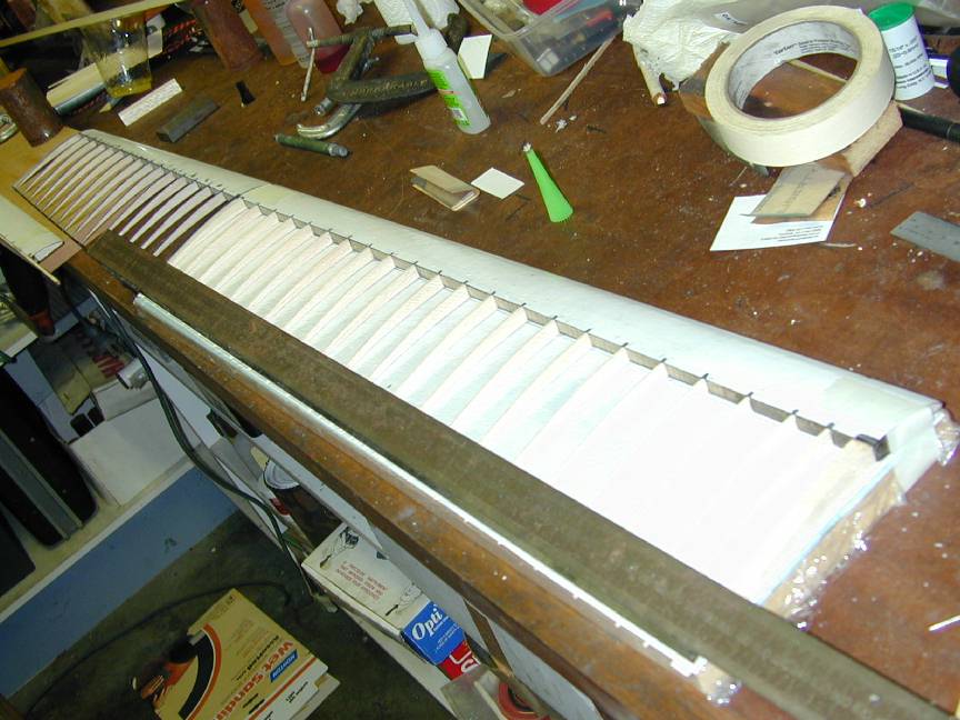
Now we come to the most time consuming, messy part: applying the carbon rib cap strips. Each must be sanded lightly on the side to be glued, cleaned (acetone again) and cyno'd to the D-box notch, rib and trailing edge. Be gentle and careful when sanding the cap strips. If the sandpaper catches an end, the strip will snap before you know it. Fortunately, the kit includes a generous oversupply of cap strips, but go easy. The caps are supplied oversize, length-wise. Keep them this way and handle them only by the length that will overhang the TE following cleaning. This prevents finger oil from getting on the surface to be glued.
At this time, the joints at the trailing edge of the wing are very fragile. The instruction sheet suggested doing the botton caps first, but the sheet was obviously written before the foam jigs became part of the kits as it shows strip packing pieces, so I decided to do the top while everything was straight and secure in the jig. I think it worked ok, but club expert (and he really is an expert), John Lewis said the instructions were more correct and my deviation may have caused my wing to loose some undercamber. Looks ok to me though.
Apply the minimum possible cyno to the shell notch, rib and TE. Push the cap strip into the notch, aligning it carefully with the rib. Press the notch end down with something the cyno won't easily stick to, like the plastic cyno bottle top, then "stretch" the cap over the rib to the trailing edge. After a couple of seconds, run the plastic cap over the rib to the TE, pressing down firmly, pausing at the point where the cap and TE strip coincide. This minimises, but does not eliminate cyno/carbon dust buildup on the fingers.
A series of articles in Aeromodeller circa 1993 says that this applies excess glue, and when squeezed out, it results in excess weight, quite apart from messing up your fingers. To avoid this, author Dave Hipperson, suggested removing the cap from the bottle and using short lengths of piano wire as dipper-sticks to apply a thin smear of glue direct to the cap strip. He wisely advocates placing the open cyno bottle in a larger, heavier base to prevent it being accidentally knocked over! I did not do this, but it sounds reasonable and anything that saves weight and keeps that mess off your fingers is worthwhile.
After the top caps are on, the overhanging cap strips ends can be trimmed to the TE with the tin snips again. The wing is now quite rigid and strong, so the bottom caps can be added, front to rear, rolling the strip down into the undercamber while rolling the point of contact on the top of the rib against a flat surface. The inner panels took me somewhere between 90 to 120 minutes each to cap. The thick end cap strips were applied first, then the "binary search" algorithm applied (like taping up the D-box) so any stresses are gradually introduced over the full span rather than end to end.
The remaining work is simple: add the tip blocks, gussets, root reinforcement plates and sand the correct angles in for the dihedral break. Then epoxy up the inner and outer panels, jigging up to the required dihedral angle (16 degrees). I reinforced the join with very light glass cloth at the D-box and trailing edge. The instruction sheet said to apply a full LE to TE strip of glass cloth, but no material was provided for this. As you'll read in Trimming and Flying, my joint was woefully insuffucuent. Any structure is only as strong as its weakest point and I'd have to say it's an error to not provide the correct material for this critical joint that allows the wing to realize its potential strength.
A final, light overall sanding makes sure there are no raised rib cap edges and that the epoxy/cyno spills that can't be wiped off with acetone are at least rendered flat. Take care not to sand away the white surface coat if you can help it though. I did in a couple of places.
Finished weights (uncovered) were stab: 10gm, wings: 140gm -- long way to go to the minimum class weight of 410gmms.
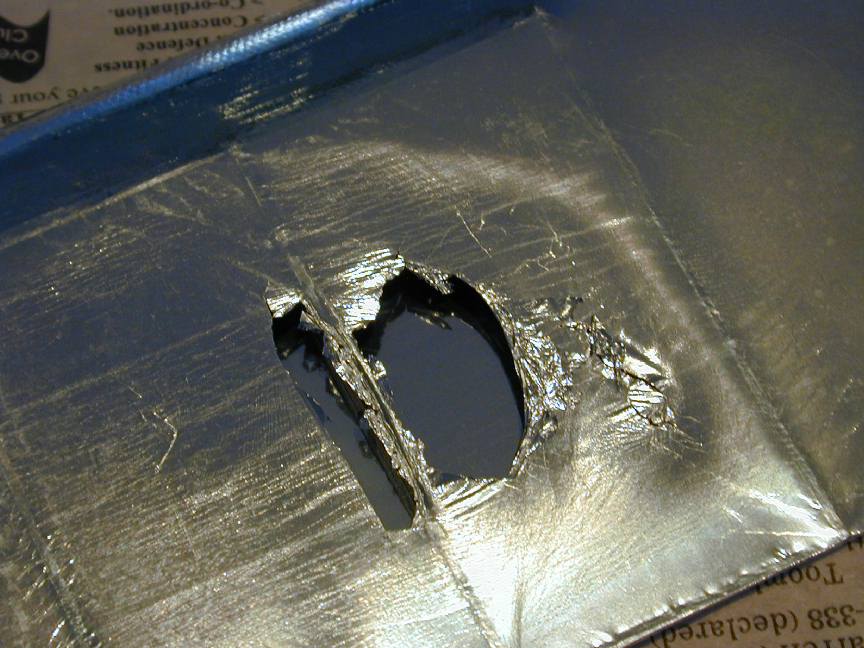
The pod comes as two carbon fiber shells. The right shell has bosses for threaded steel inserts that will mount the very neat W Hobby "cartridge" timer/hook/wriggler assembly. The left has a cutout for the timer access plate. These shells are pre drilled for the wing joiner and access holes. The halves must be joined, the tail boom added and all the plumbing installed. Sounds straight forward, right?
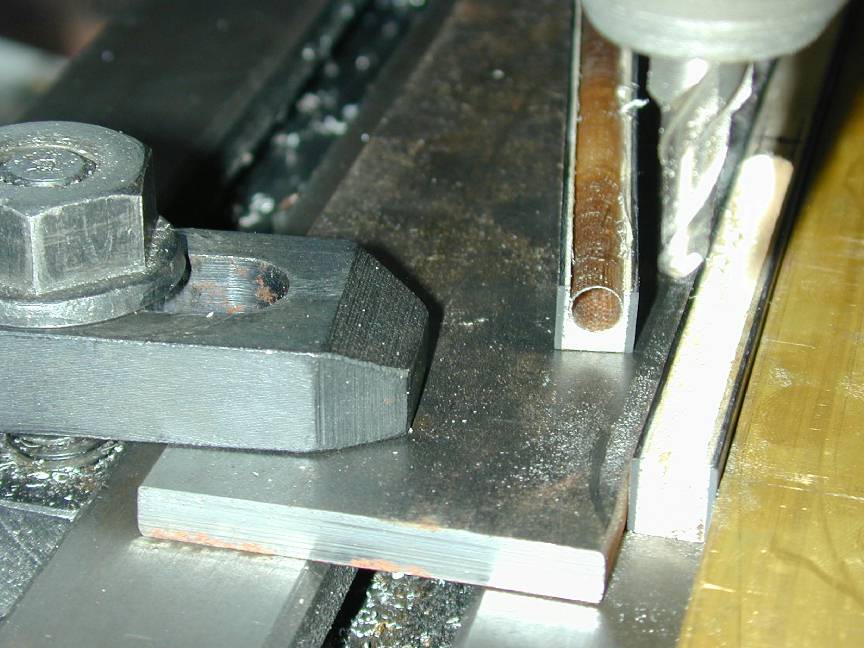
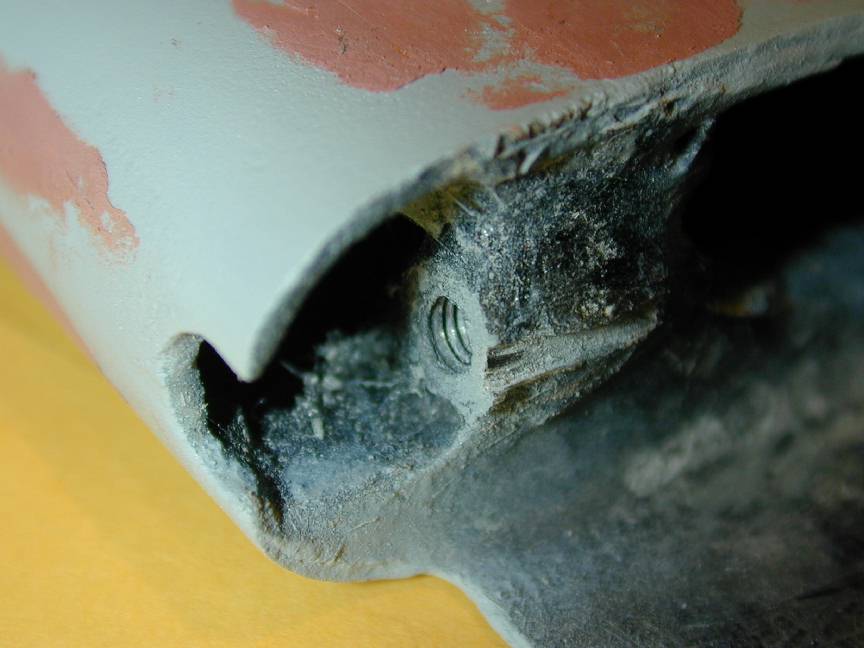
Here Ron gets ready to make Big Dumb Mistake Number 4 by using the hole for the rear cartridge mounting screw to control the alignment of the halves. Stupid, stupid, stupid Ron! After it was all over, the slightly undersize wing joiner holes were reamed to a close fit on the joiner and the rod slid through. You can see the result in this picture. If I'd applied even an ounce of thought, I'd have reamed first, then jiggled the sides to produce the correct line-up of the joiner; instead my rod is normal to nothing. It has to be fixed and the only way to do this is open out the holes, jig everything up, then epoxy in a stub tube (with carbon tow) to get the rod alignment correct. But first that stub tube had to be made as the kit contained only enough tube for the wings with nothing at all to spare.
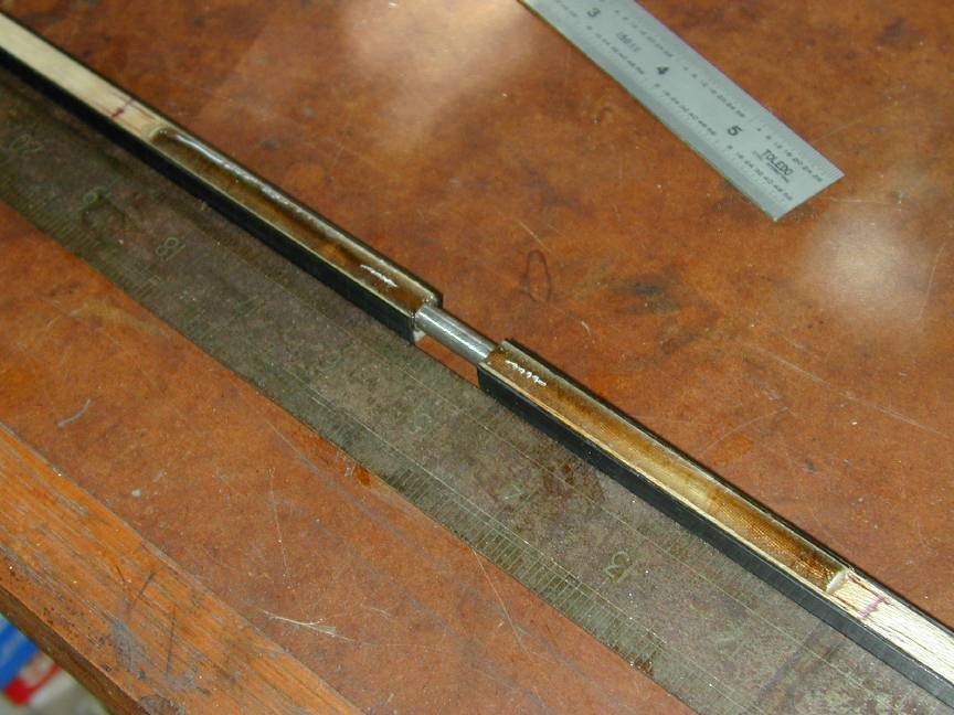
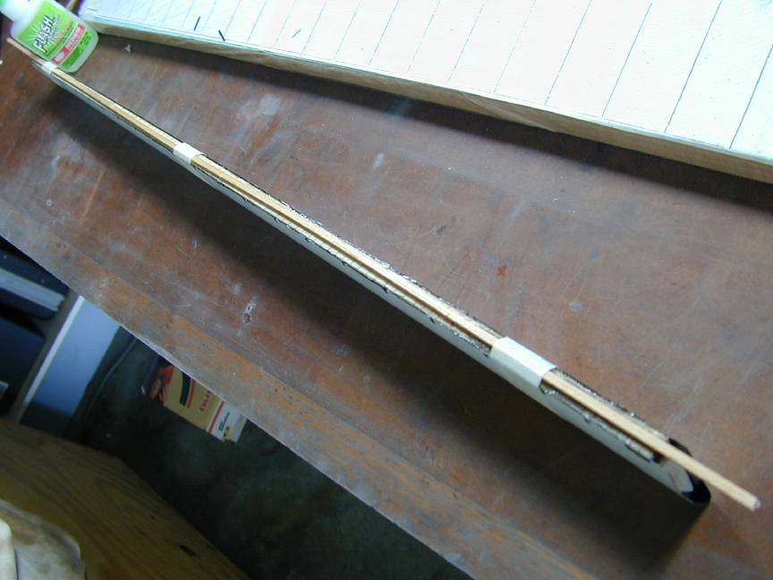
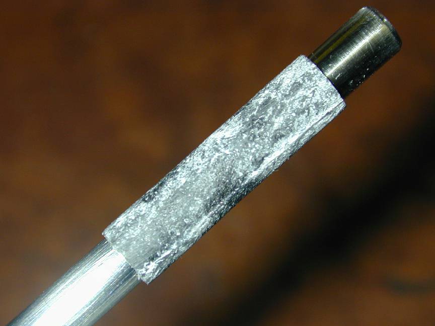
First attempt: oil the wing joiner rod, wrap carbon tissue around it and wick in thin cyno. Next, slice the thing off the joiner a bit at a time and try again. In succession, I tried petrolium jelly, silicon spray and silicon grease. All refused to be separated from the rod except by cutting them to pieces. Finally I wrapped one layer of kitchen cling-wrap over the joiner and repeated the well rehearsed carbon/cyno application. Perfect! The heat generated by the cyno setting almost melted out the wrap and the result was a very close fitting, very hard tube as seen here. With this in place between the pod sides and wings, a goop of carbon and epoxy was applied internally and the problem fixed -- but it would have been better to have avoided it in the first place.
Three other problems were encounteded with the pod. First, lack of any anchoring points for the forward threaded insert (the one accessed from the bottom) required some careful cyno, carbon, epoxy build-up work; not difficult, just tedious. Next, the number and degree of surface flaws in the mouldings needed quite a lot of filling and sanding to get a show-case finish that will last until the first heavy landing. I've probably added more weight in doing this than strictly necessary, but it's going to need a lump of lead in the nose anyway.
Thirdly, and perhaps most annoying of all: the contour of the top of the pod aft of the wing high point. Whatever wing section it was based on was certainly not the Benedeck B6356b used for the Superba 2220 wing. The pod has a much higher camber giving a rather untidy 2mm step between wing and pod at the worst point. There are 5 different wings available in the Superba range. Two use the Benedeck section while the other three all employ a Makarov section. This one appears to have more aft camber, so perhaps the pod would blend better with it. To fix this, I'd have to cut the top of the pod away completely and do some difficult internal filiting. It's simply not worth it, so I'll live with the less than perfect blending and the tut-tuts of more observant club members.
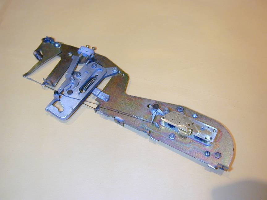
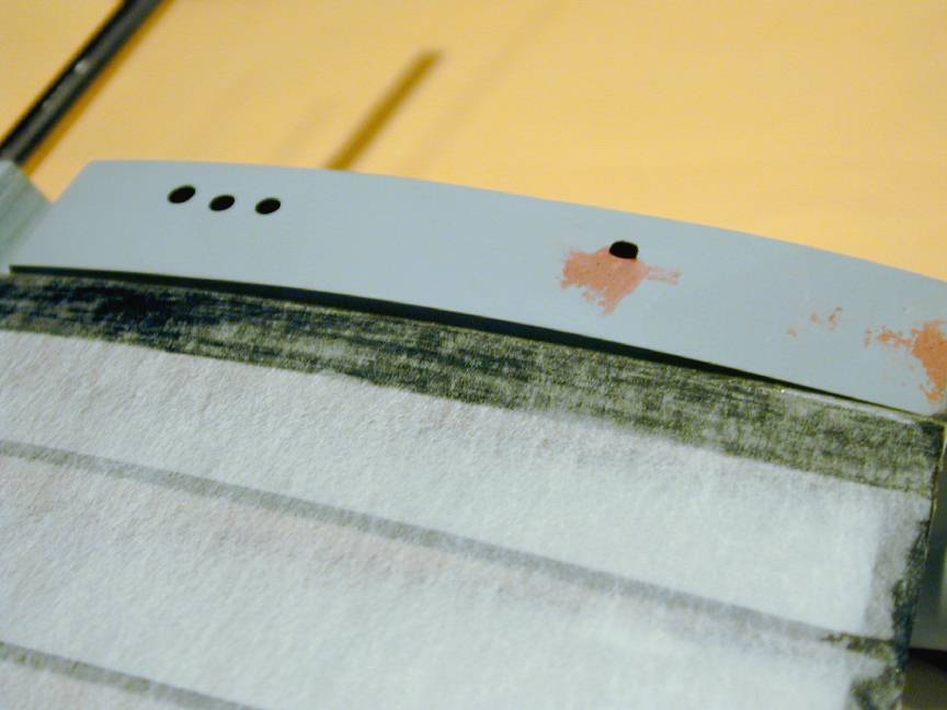
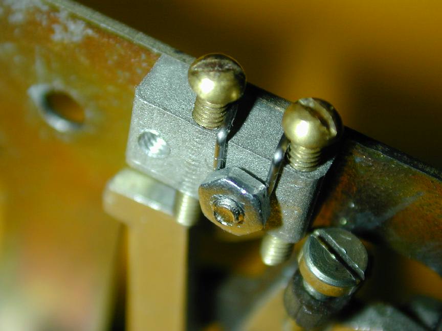
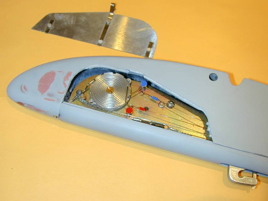
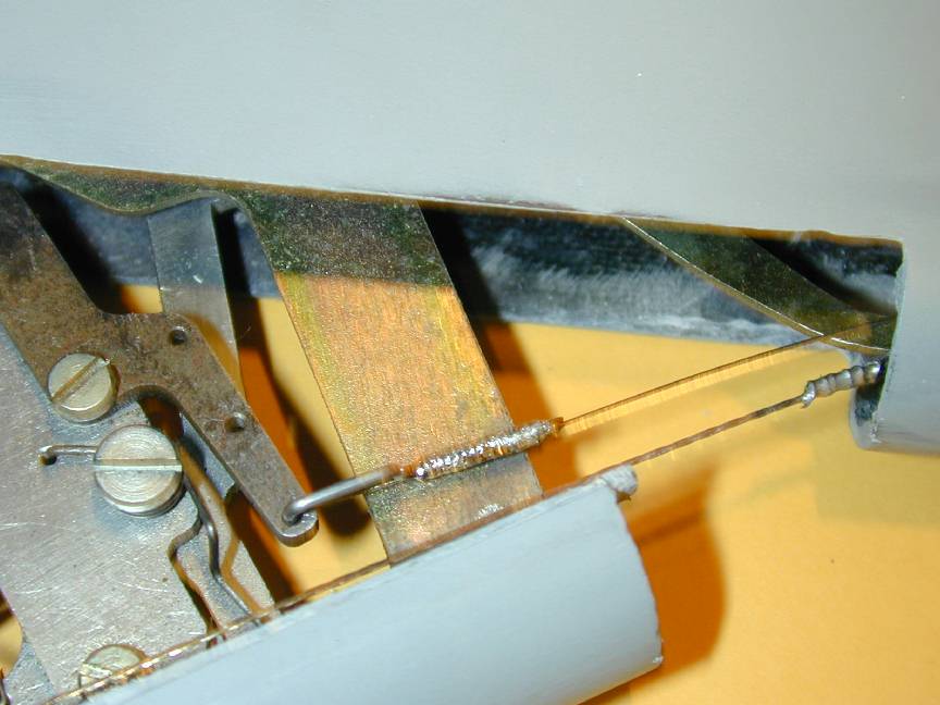
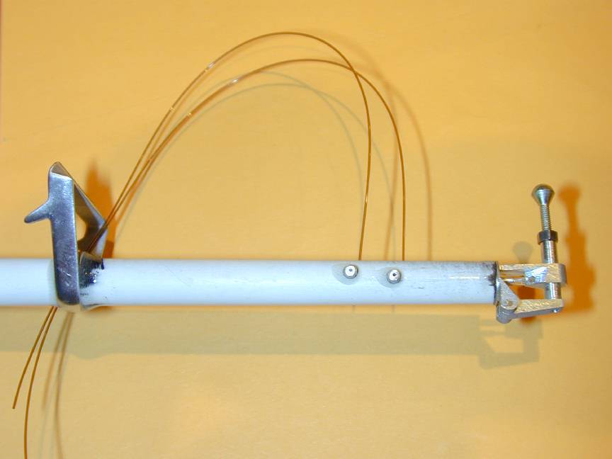
The holes visible in the top of the pod provide adjustment for nearly all of the turn settings. The 3 at the front set the rudder position for zoom, glide and circle tow. The one on the right sets the wing wriggler position for glide; the deflection during tow being adjusted by a screw clevis in the wriggler line, accessed through the timer hatch. Rudder during straight tow is set by a screw clevis (provided) at the rudder horn; the forward stop of the circle tow hook being fixed. All access holes came pre-drilled with remarkable accuracy. Only the wriggler hole had to be moved sideways a little for perfect allignment. The two screws that set the rudder position during tow and glide were rather loose in their positioning block on the cartrige top. If the model is transported long distances over rough roads, they will certainly change position due to vibration. To prevent this, I've added a small music wire spring that pushes against the screws providing enough friction to keep them in place. The spring is retained by a nut on an extended M2.0 screw that secures the block.
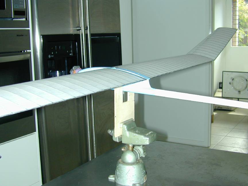
The tail boom is a carbon tube, very light and finished with a white surface coat. No dimensioned or full size drawings are provided to give the explicit placement of the stab and fin, but the general arrangement sketches, together with the tail moment dimension appearing in the table on the W Hobby Superba Family web page provides enough infomation--highlighting again that this is a kit for the experienced builder. After a trial fit and measure to establish the distance between wing TE and stab LE (730mm), the boom length was adjusted and was ready to epoxy to the pod.
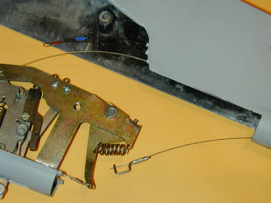
Initially, I had run all control lines through the unattached boom, but abandoned this idea for two reasons: (1) concern that epoxy squeezing out on the inside might glue up a line, and (2), the danger (certainty?) that one or more of the lines would end up twisted! So the boom got glued up and aligned sans lines. A number of turns of kevlar thread were wound around the very front of the boom to ensure that it splits somewhere else in a hard landing. After curing, each line was fed through from the rear and kept under tension as the next went in to prevent any becoming twisted. The thin nylon tubes just visible at the edge of the pod hatch opening keep them separatated after installation. Looking in the hatch, the forward pin on the scroll holds the wing wriggler and bunt tension line; the blue line is the buntroller and the red line is the DT/glide stop.
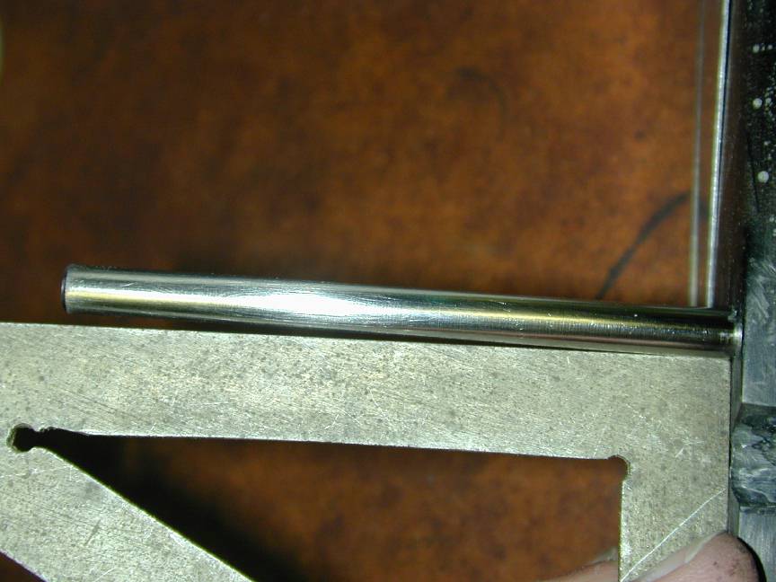
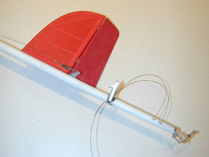
The (steel) rudder pull cable attaches to the zoom arm of the hook which is only accessable when the cartridge is completely withdrawn from the fueslage. Notice in the next photo showing the fin from the left that the cable exit point is well forward of the fin. This allows adequate "free" cable length to be pulled into the boom after detaching the rudder clevis so the timer cartrige can be pulled down and forward enough to easily detach the front rudder cable clevis from the tow-hook zoom-arm. The little piece of bent wire bound and soldered to the cable was provided, pre-bent, in the hardware pack--though no indication was provided saying what it was for, so I assume I've used it for the intended purpose!
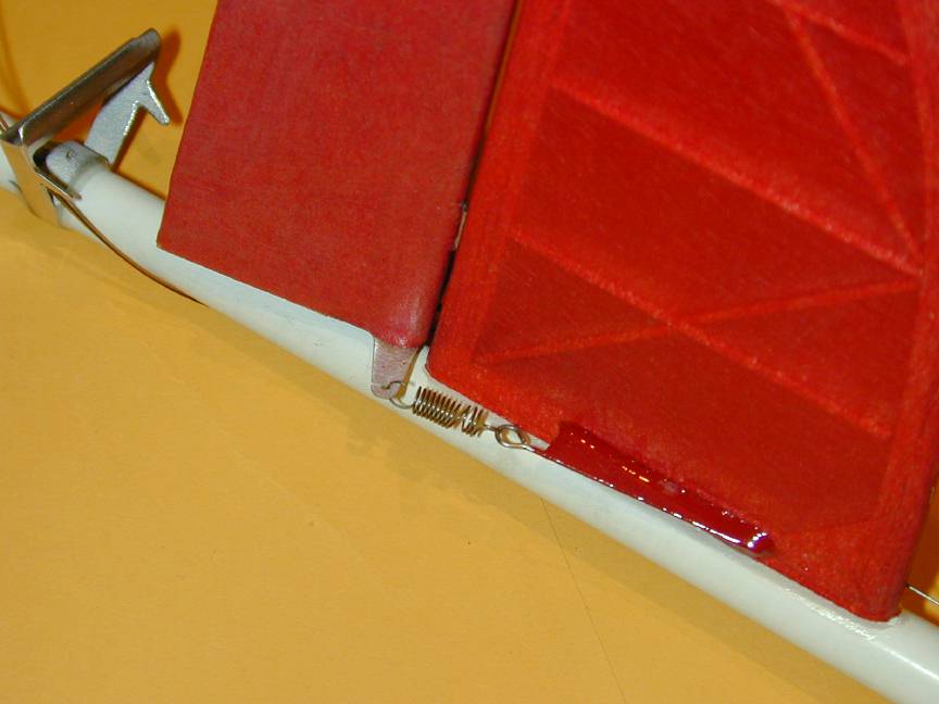
Surprisingly, the fin and rudder come completely finished and covered with red tissue (look at the kit contents photo). Following modern A2 practice, there are no rudder "stops" thus reducing weight at the back end. To ensure that the rudder position remains consistant, the kit includes a very fine steel rudder pull-cable. I've added a light spring to provide the appropriate tension, finding these are far more reliable than rubber bands.
The "Buntroller" provided is very nicely made and light. On the down side, the tow-position stop is a bit short for my liking. If the top of the roller leans forward too far over-center, the bunt spring will tend to lock it up resulting in no bunt and a stalling glide trim. Better if it were a little longer allowing it to be adjusted incrimentally to the optimum length for snappy action. The screw section that adjusts stab angle during tow was on the loose side, so I've added a lock nut to guard against accidental movement due to vibration during transport. The size seems to be 10BA. My kit contained two cast aluminum stabilizer mounting/DT pivot posts to choose from. One was the normal "T" shape we are accustomed to seeing; the other is a very neat and light triangular shape shown here (after a bit of careful filing and polishing). I like the little prongs to take the DT bands.
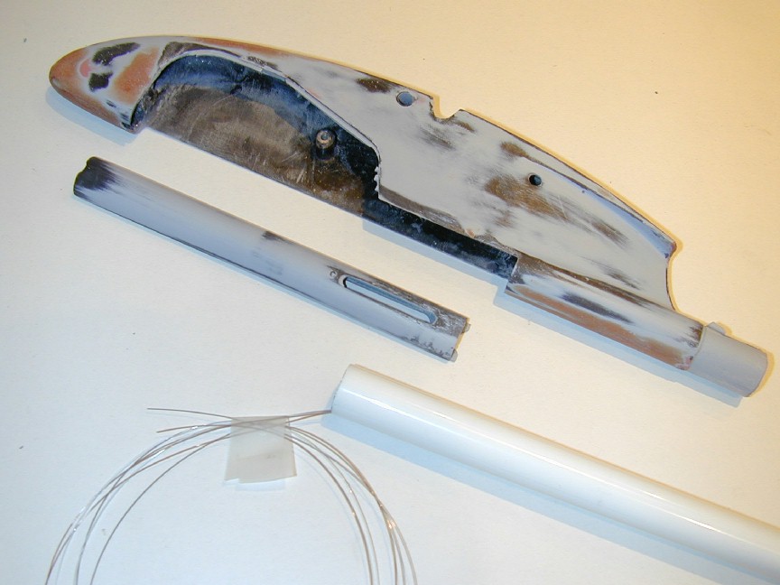
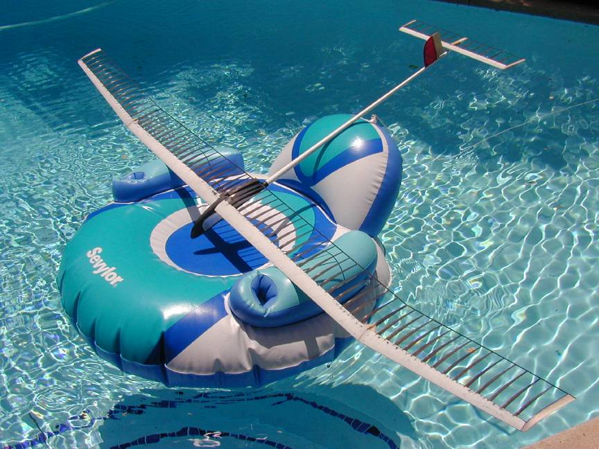
With lots of vacation time outstanding, I took 4 days off to build the Superba 2220 in the height of Australian summer of 2002. The actual effort required in hours is not all that much, and several of the processes surrounding spar and D-box construction require lengthy curing periods, so a concentrated building effort is not really required. A few hours work in the evenings would produce an airframe in not many more days than I took. Instead, I could spend the hot part of the day reading and drifting around the pool on a rubber raft (it's a hard life Downunder). Figuring the Superba could use some relaxation too, it was allowed some naked pool time as seen here.
The kit contains polyester paper and metalized mylar covering for the wings and tail respectively. I'd not worked with the polyester before, but found it very easy to apply using "Balsalock" paint-on, heat-activated adhesive. This was brushed onto the D-box, TE and rib caps, allowed to dry, then the paper laid over it, shiny side up. A few light touches with the iron assured placement, then it was firmly adhered at the ends first, followed by TE, LE and finally over the ribs and shells. The Balsalock worked perfectly on the undercamber, except for the rib I somehow managed not to coat! This was fixed by bleeding full strength dope over that rib from the outside and pressing it down until the dope dried. The top surface was covered first, wrapping around for the full TE width and about 3mm at the LE underside. The bottom was then glued to the overlaps and trimmed to the edges. Take care though; the covering is cut to width and length. If you trim an inner panel for use as an outer, it will ruin your whole day (lucky I noticed this first, for a change). The surfaces were heat shrunk and given two coats of dope thinned 75% for no other reason than I happened to have some ready made up. One coat may have done; the surface feels good and the covering is tight. Weight for both panels after the first coat: 154gm. The second coat added another 4gm.
Covering the stabilizer was in contrast, not a happy experience. The supplied material was very light mylar, metalized on one side. Lacking any experience with this material, I elected to apply it with the metalized side out (that's the side with the most "shine"), again using Balselock heat activated adhesive. I also decided to cover in one piece wrapping around the trailing edge. Let's number this as Big Mistake #5. It made it far too difficult to get the mylar uniformly tight over the frame before shrinking. I subsequently found out that this stuff does not shrink very much. I was already very unhappy with the finish, then I burnt a hole in the mylar trying to remove a wrinkle. Attempts to patch the burnt bays just made things worse, so I ripped the whole mess off and applied clear, adhesive backed mylar. Even though this material was very thin (0.0005"), it still almost doubled the weight of the unit, and being posed way down that long boom, I knew I was going to have to pay a severe nose weight panilty. C'est la guaire, I guess.
None of the instruction sheets mention the CG location, but a quick email to Vidas got an instant reply: 52 to 54% of root chord. The root chord is 150mm, so I made a pencil mark at 80mm (approx 53%) back from the leading edge and sat the fully assembled model in a U frame from 1/8" balsa with the top edge rounded. Weight was added in the balast box area until it hung level. The amount of weight was measured with electronic kitchen scales (53 gm) and the equivalent made up in sheet lead that was epoxied into the nose compartment. Finished weight was 38 gm over minimum, with turbulator and hi-visibility paint trim still to come. I'm going to call that not bad for a first effort in this construction.
The ratio of tail to nose moments is close to 5:1, so every gramme saved at the back means 5 less at the nose and 6 less for overall model weight. W Hobby quotes their pre-made stabilizers as weighing 8 grammes. If I'd achieved this, my model would be about 48 g lighter and I would have been in the happy state of having to add balast to reach the class minimum!
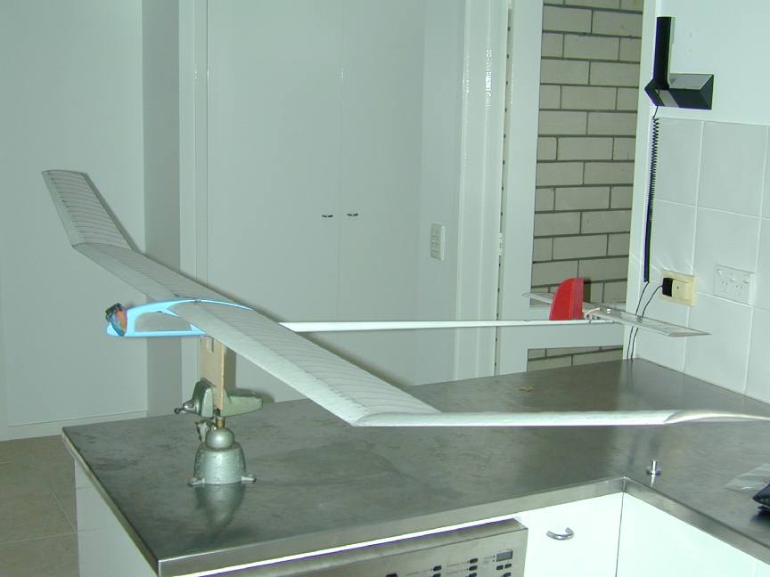
Last task I'd left myself was the installation of the pins that fix the wing incidence (one fixed; the other in the wriggler). Now we have a dilema, what incidence should the wing be at in relation to the pod and fuselage center line? And does it matter much? The angle between lines projected through wing and stab chords is called the "declage", or sometimes, the longitudinal dihedral. For positive pitch stability, it needs to be some few degrees less than 180. Now given that the CG is about right, the stab adjust bolt will be used to get a flat glide just short of a stall and the magic angle will have been achieved. Ideally, at this angle we'd want the fuselage to present the minimum profile drag, which is why the angle at which the wing sits, relative to the fuselage longitudinal axis is important.
Without a full size, or accurately scaled side view, it's hard to measure wing incidence. It seemed that with the wing TE located at the aft pod contour, the incidence was between 2 and 3 degrees, which is a reasonable figure. Ok; we go with that--holes for pins got drilled and tube bushes installed in the wing, arriving at mistake #6. I really should have done this before covering the wing. Even worse, I forgot to crimp the end of one of the tubes before gluing it in place (crimping the end lightly prevents the pin from sliding through the tube into the first wing bay). Now I need a long pin that uses the first rib as an end-stop and that has the feeling of a failure in the making about it. All could have been fixed if the wing was still uncovered... *sigh*.
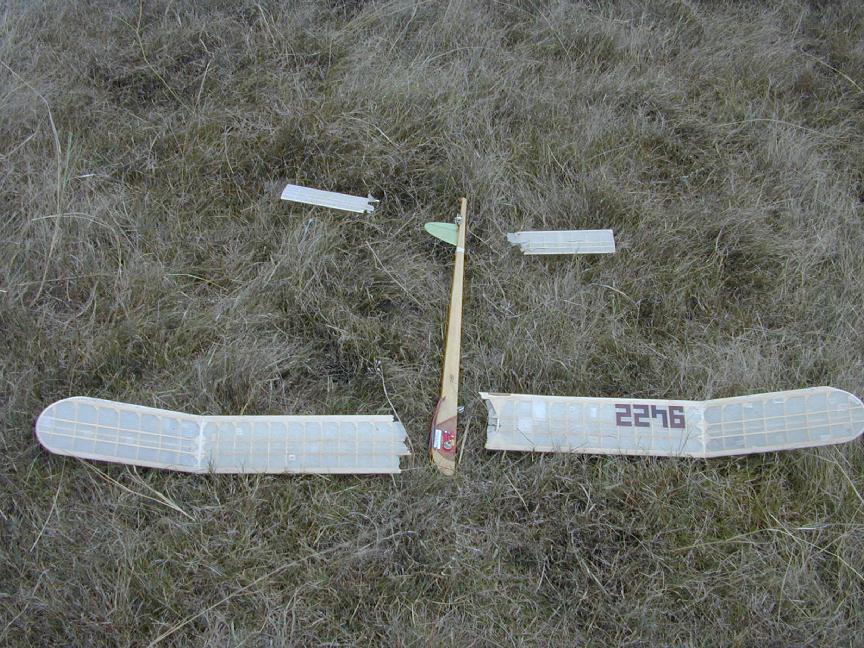
So, out to the field, abundantly equipped with long grass. A few test glides got the tail incidence adjusted to what might be a reasonable position, but you can't really tell until the model comes off the line and starts circling. My plan was to launch with the the hook unlatched and every gizmo but the auto-rudder and DT disabled. So with the DT set for about 20 seconds and with a light breeze blowing, away we go. The Superba tracked straight from release climbing strongly with a good, but light pull. At about 15 meters, there was a light crack noise and the port tip panel folded up. Knowing a bad prang was now inevitable, I ran towards to model to release tow line pressure. I didn't notice, but my helper says that the starboard tip panel failed as well just before the model hit. So much for the model I could not pull the wings off!
Damage was fortunately light. There are a few scratches in the carbon fiber fuselage pod (so much for my efforts getting a show finish) and the fin had ripped of--probably from inertia. There was no damage to any of the D-boxes. or trailing edges. A Board of Inquiry was quickly convened and concluded that the dihedral joints had failed under very, very light load (well, duh?). Opinion regarding the cause differed: one board member screaming "What? No dihedral braces? No wonder they failed!"; another muttered, "No, that's the right way to join them". My defence: I was just followed the instructions.
Post-incident Conclusions:
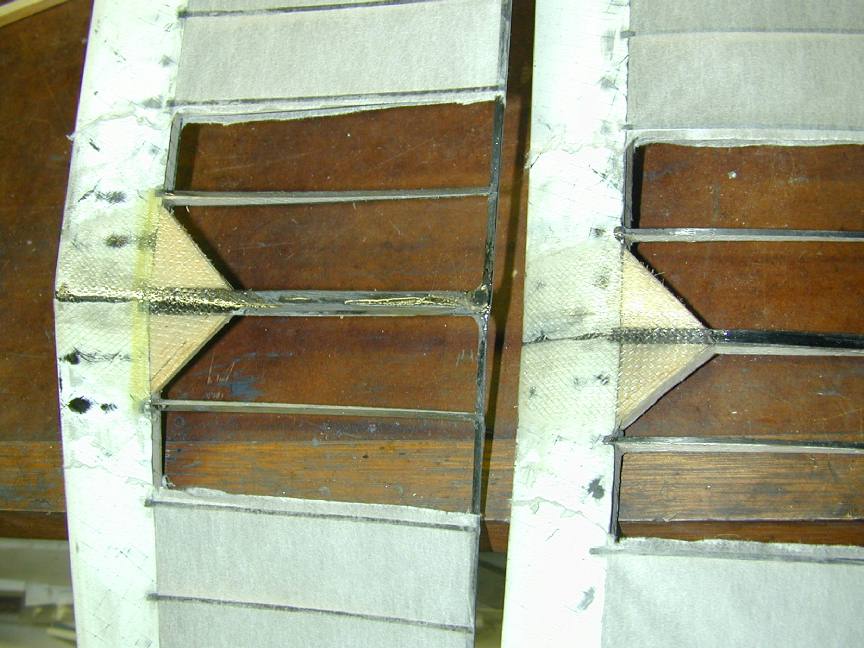
Here's the repair I decided on--which is also the way I should have joined the wings in the first place. The gussets are full depth, sanded to wing section, allowing the fiberglass reinforcement to act in an area centered over the spar. The cloth is applied with the weave at 45 degrees to the spar for maximum strength and tapers towards the leaging edge. If you look closely at the bottom reinforcement, you'll see a yellow stripe along the spar reigon: this is some kevlar tow applied under the glass cloth making the joint a bit stronger under positive "G" loads. After this fixup, the weight of the wings risen to 162 g, a 4 gramme increase. Inevitable, but not as bad as I'd feared.
So, out to the field, again. No problems with wing fold this time! The wind was too strong and the grass too long to circle tow without risk to life and aging limb, so trimming was constrained to straight tow--first without the wing wriggler engaged, then with to get the rudder adjusted to compensate for the drooped starboard TE during tow. The design of the Superba and its cartrige mechanics section are excellent. All adjustments are easily made on the field without need to disassemble anything. All told, the Superba made 8 flights with the DT set between 20 to 45 seconds. More trimming is needed, along with a calmer day to try out circling and bunting, but I'm well pleased at this stage.
Flying finished for the day when the tube retaining the wing wriggler pin broke loose and disappeared into the first wing bay as a result of a hard landing from a hand launch test glide. I will add a ply or epoxy laminate plate on the inside of the root rib to ensure this tube is well anchored (and crimped) this time. I've also added 10 BA jam-nuts to the two clevis adjustments on wing wriggler and rudder cable length to ensure these can not easily be upset.
The glide incidence of the stab depends on the pull of the DT bands against a knurled nut and the DT cable. This cable (0.4 mm nylon line) makes a 90 degree bend around a small diameter tube where it exits the fuselage. I feel the nut also needs locking in some way and I may go to a larger diameter tube so the bend in the nylon is not so abrupt as the position has a degree of "uncertainty" about it. More trimming will tell.
At this time (Feb 24, 2002), more trimming and testing is required, but the model has flown sufficiently to demonstrate its capabilities and ease of adjustment of all essential components. Although I made a number of mistakes of varying degree in my first attempt at this type of construction, the model meets my expectations and we will see how well I manage in this year's contests. If you've read this far and decide to build one of the wings in the Superba range, you should be able to avoid all my dumb mistakes--especially the insufficient kevlar wrapping of the spar and build--if you'll pardon the pun--a superb, hi-tech F1A competition glider.
The W Hobby Superba is a well designed model available as a very complete kit, of outstanding quality at a reasonable price (especially if you live in the USA). While it does require the builder to be relatively a experienced modeller with some experience in conventional A2 "Nordic" models, the quality and fit of the parts will reward you with a fine model. Despite my earlier assertions that I never wanted to see another carbon cap strip ever again, as long as I live--driven by the time it took to clean the mess from my fingers 5 times--I have to agree that this method of construction is faster than "conventional" and the strength/rigidity is astounding. I'm already trying to talk myself into ordering a Superba 2460 kit for fly-offs and the fun of building it.
Back to BFFS Inc Page
This page designed to look best when using anything but IE!
The Kit
Wing Spar Fabrication
D-box Construction
Wing Construction
Fuselage
Fin, Rudder and Tail Fittings
Covering and Finishing
Tail: 14gm Wing Joiner: 36 gm Wings: 158 gm Fuselage: 240 gm Total: 448 gm Trimming and Flying (1)
Trimming and Flying (2)
Conclusion
![]()
 Home
Home
Please submit all questions and comments to
[email protected]