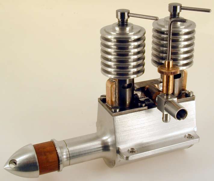
Building the Sparey In-line Twin.
![]()
 THIS PAGE UNDER CONSTRUCTION
I confess. I'm a complete sucker for twins. They look mysterious, powerful and expensive. The amount of repitition work is minimal and the challenges not so large as one might think as the Prototype Taplin Twin project demonstrated. More cylinders need lots of repitition, but twins are *just right* (IMHO). I've been stock-piling casting for twins. A Westbury Ladybird and Craftsman and Chunn alternate firing twins; an OK twin would be the penultimate, if I could afford one. Get the idea? I love twins!
Laurence H Sparey never, to my knowledge, designed nor built a twin cylinder diesel, but once Ken Croft light the spark, I had the "tribute" engine drawn out in a day. We'd separately decided that a split main bearing on a Taplin-like bobbin would be the way to go. I recalled how Mr Radford used the idea of a grub screw that bears on an inclined surface to get the tool holder to "snug down" on his ball turning tool. The same idea is used in my AMF shaper to hold the rotateable clapper box mount to the ram. We can use this to securly position the split bush against a little stop inside the case bore. As you can see in the sectioned general arangement (GA), an O ring will provide the seal, but may not even be needed.
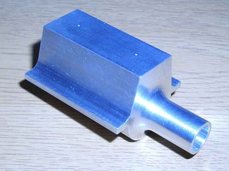
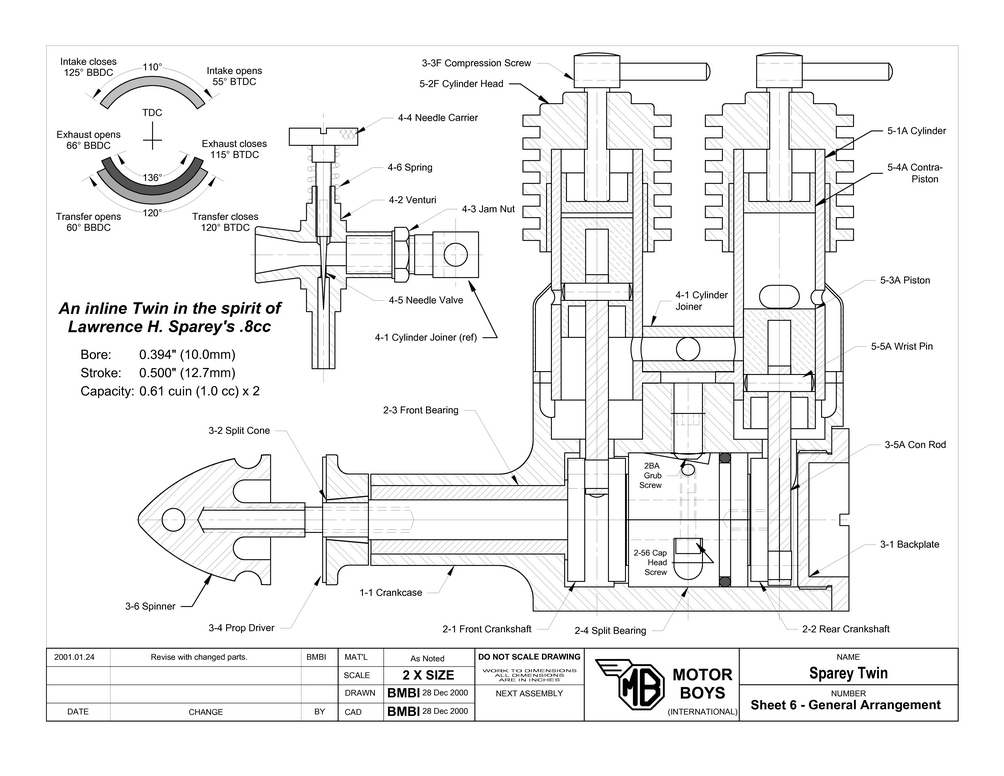
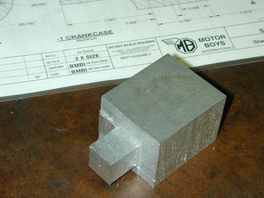
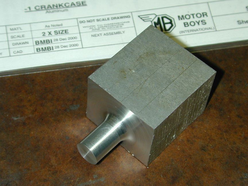
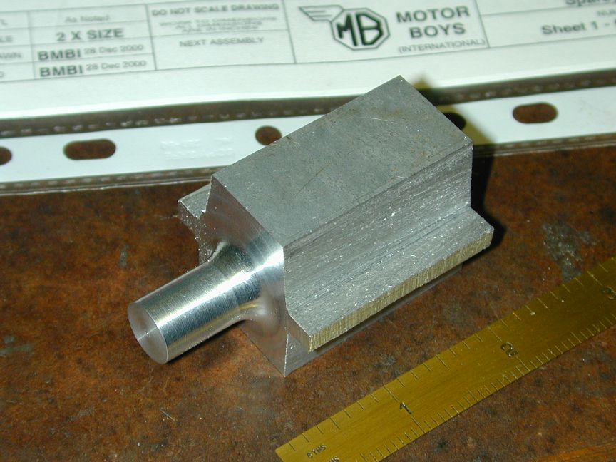
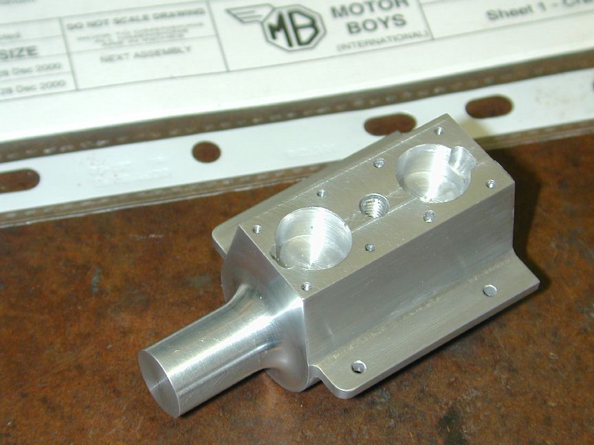
While I decided to go big bore and evaluate the revised cylinder design first in the Millennial Sparey, Ken went straight into metal cutting and produced this beautiful crankcase. The hole between the cylinders is for the bearing retaining grub screw. Ken says he will now tumble his case to ge an equal, all over finish. Braggard! If my finished case looks half as good, I'll be extatic!
The challenge for in-line twins like this is how to isolate the case cavities yet achieve a lightweight, reliable, simple to machine design that provide gas tight isolation, a good shaft bearing and can be assembled and dis-assembled when needed while maintaining accurate positioning and correct cylinder/shaft alignment (having spelt all that out, I'm surprised we didn't give up right away!) Taplin and Chunn used a split case. This works well, but requires extra metal to form an adequate mating flange.
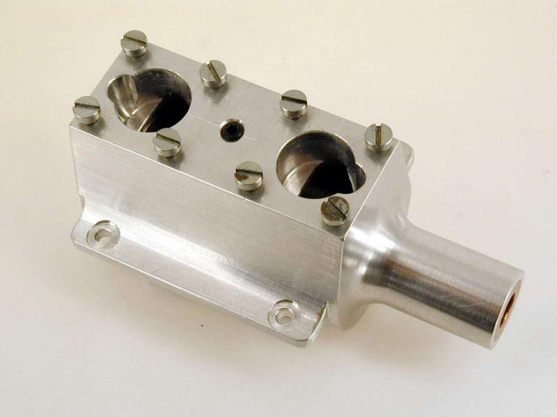
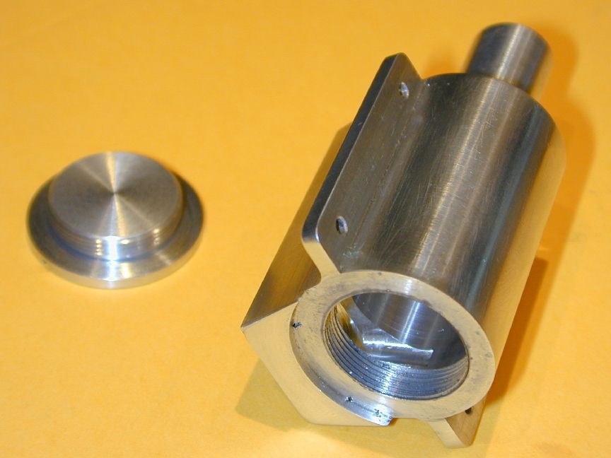
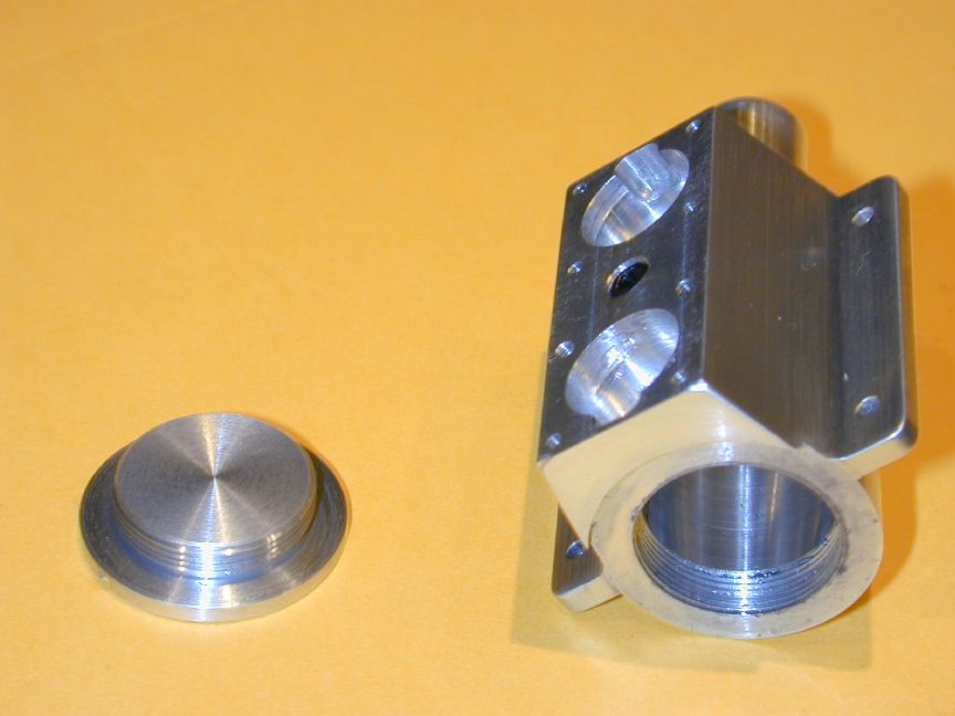
On production engines, Taplin changed to a center case with a striaght thru bore, fitted with end plates. A center "bobbin" shaft was made from two splined sections and assembled on a one piece bearing that was a push fit into the case bore. Not bad for an 8cc engine, but at the size we're talking here, a two piece crank bobbin would be too hard to make, so we decided on a one piece crank section and split bearing. Here's Ken's prototype bearing. A close sliding fit makes it rigid and ensures correct alignment. A forward "stop" turned in the case bore with a grub screw and ramp gives repeatable positioning. The "O" rings ensure a gas seal. Still some precision work required, but relatively simple, robust and reliable.

Ken finished his twin around mid January, 2001 and encountered an unusual problem on initial testing. It would run briefly on both cylinders with a demented scream, then drop back to one cylinder only. Eventually, the front piston stopped moving, leading him to think he'd suffered a broken rod, or wrist pin. The trouble was stranger than that though. When pulled down, he found that the front pin was missing altogether? It was later located in the rear cylinder! We believe this transmigration of the pin must have happened during the pull down, with the errant pin hiding in the cylinder inlet joiner pipe, waiting for it's chance at a better life in the rear pot. Mine will have press fit pins for peace of mind.

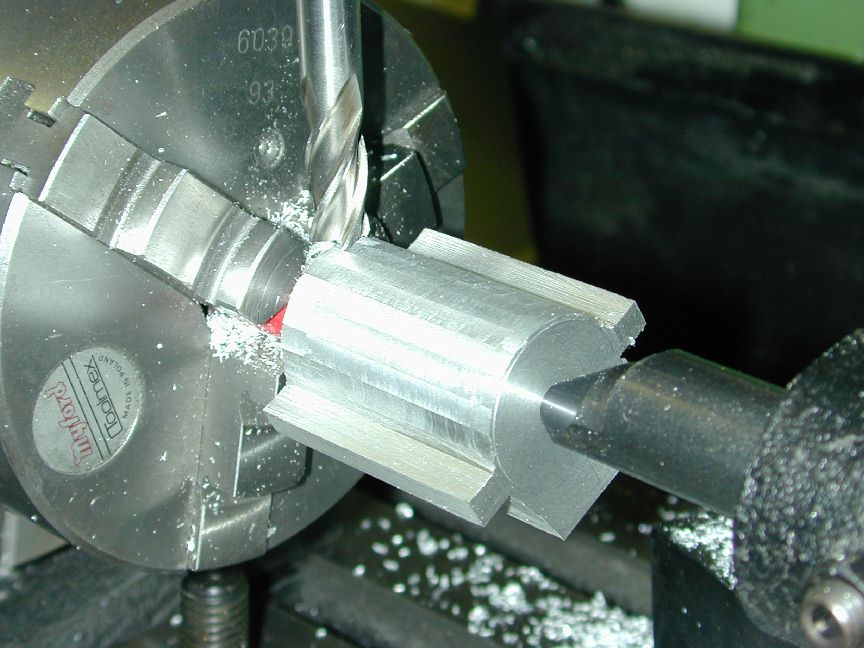
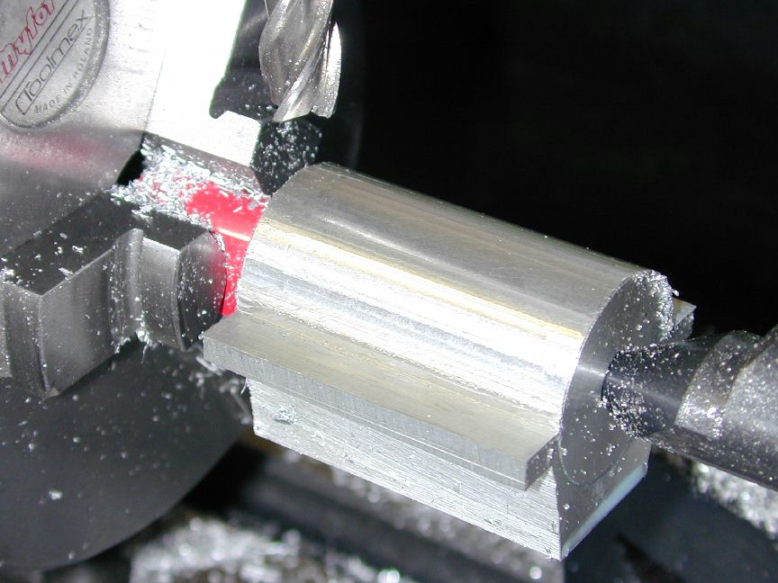
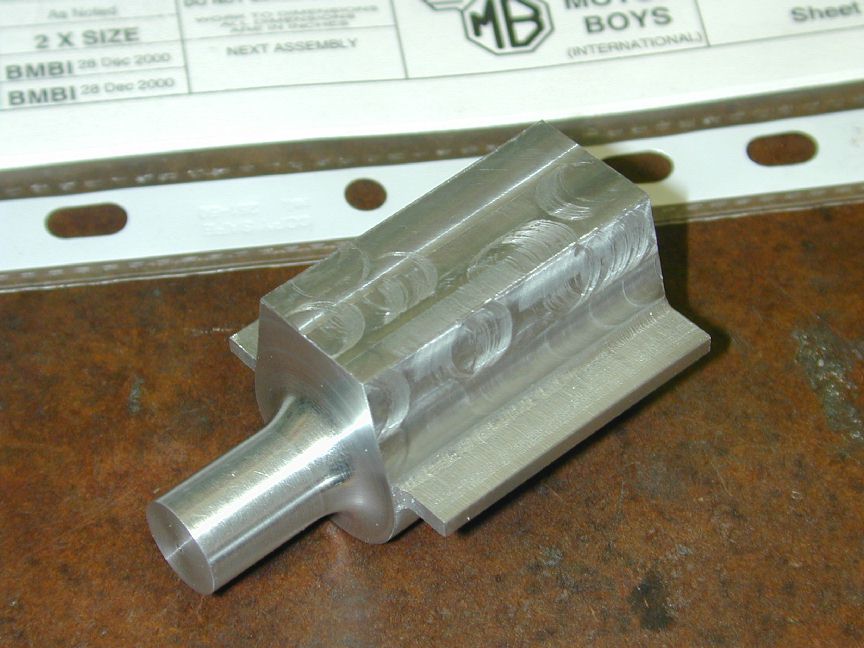
Ken's twin uses original 0.63cc cylinder assemblies. As the modified 1cc design has proven a roaring success on the Millennium Sparey, mine will use those. Perhaps the larger capacity will make cylinder charging through the "T" less critical and mine will not exhibit the tendency Ken's shows where the front pot drops in and out at whim. These shots show the fins being formed on a holding fixture. The tool is 1/4" diameter HSS, ground with 3 degrees rake on the sides (both vertical and front to back). It cuts like a hot knife thru butter. In the next shot, we see the raw cylinder, rods, compression screws and cooling fins. I've profiled the fin edges like Ken's. Comparing these with the square fins on my single, it seems to "tame them down"--the square fins make the single look a lot more aggressive (and at 9K RPM, it sounds it too!)
 |
 |
 |
 |
 |
 |
 |
 |
 |
It's been a long time between drinks; here I am in December 2001, almost 12 months since the drawings were made and my twin is still not finished. Maybe it can be done before 2002; we'll see. But there is progress--I know from a lifetime of unfinished projects why my unfinished projects become, well, unfinished. They all stall waiting on a step that I either don't have a satisfactory process worked out in my mind, or I have a process that is so un-fun, I don't want to start it. I also know from experience that when I start, the problems turn out to be non-problems and progress is swift, but have I learnt from this? Apparently not.
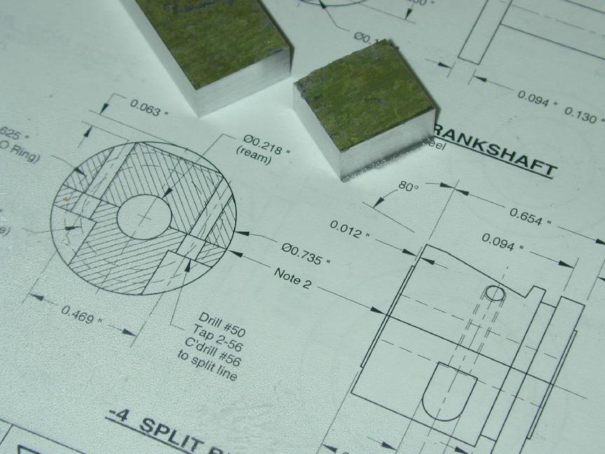
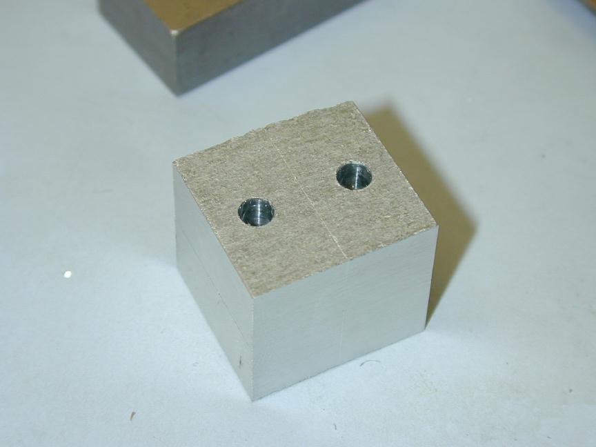
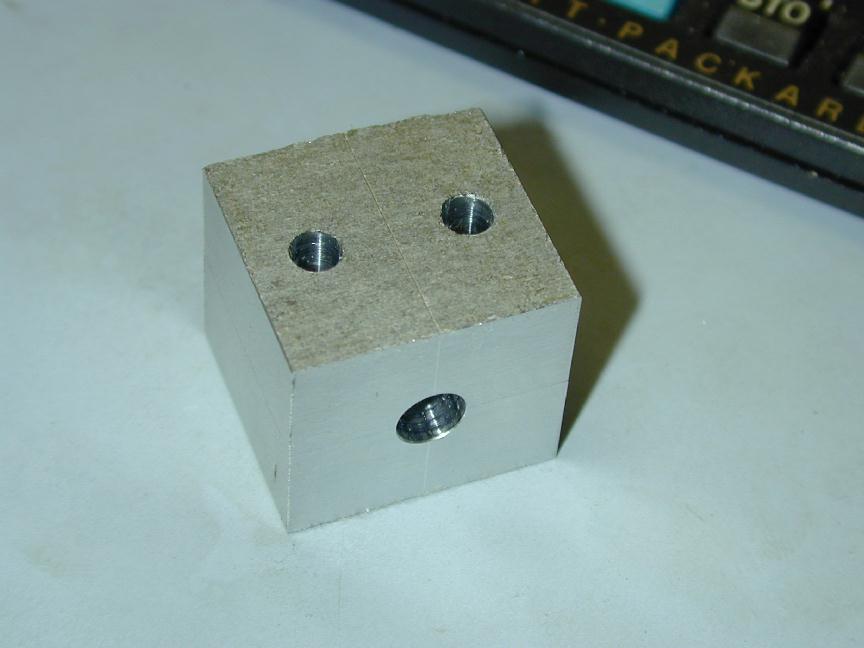
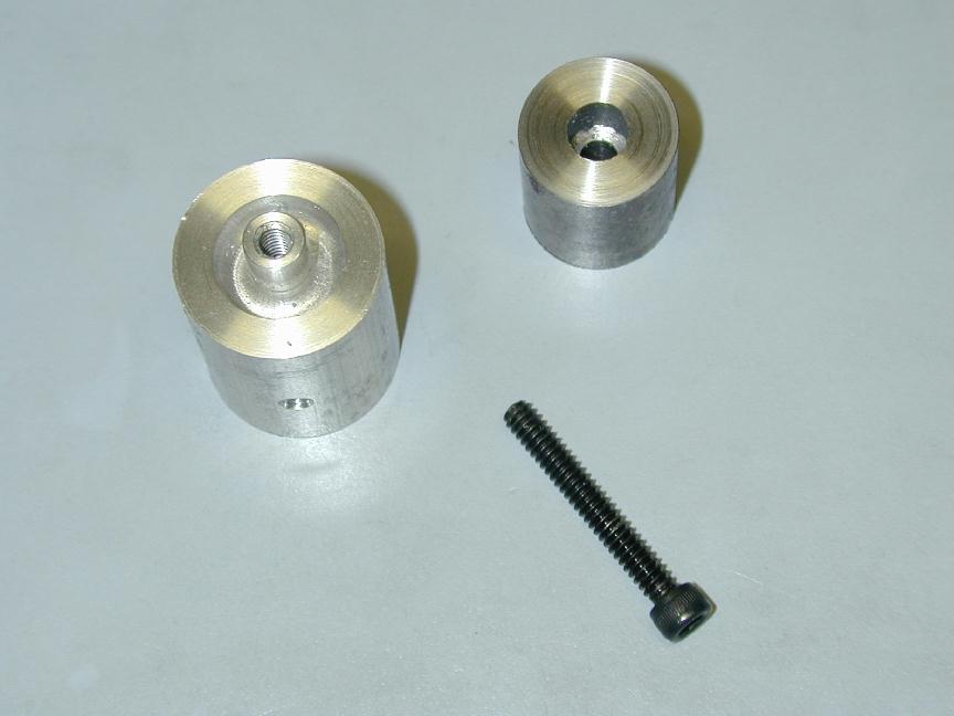
The Twin stalled on the center bearing. I managed to destroy three slitting saws trying to horizontally split a piece of bronze rod so it could be soldered together and turned into that bearing. Ken Croft had told me he'd simply made his out of dural, so finally (after a long break), I decided to follow suite. In the photo block below, we see two pieces of 3/8" 2024-T6 plate (with old zinc chromate primer) that will form the split bearing. In the next shot, they have been drilled, tapped and counter bored for the 2-56 cap head bolts that holds the bearing together. Next, they have been drilled and reamed by centering the block in the 4-Jaw chuck on the lathe. The mating faces were lapped on 800 glass paper and a surface plate before this step, so the bearing fit should be good after re-assembly.
 |
 |
 |
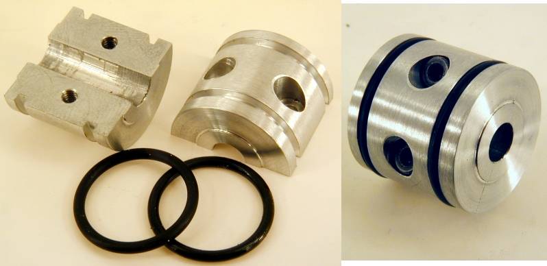
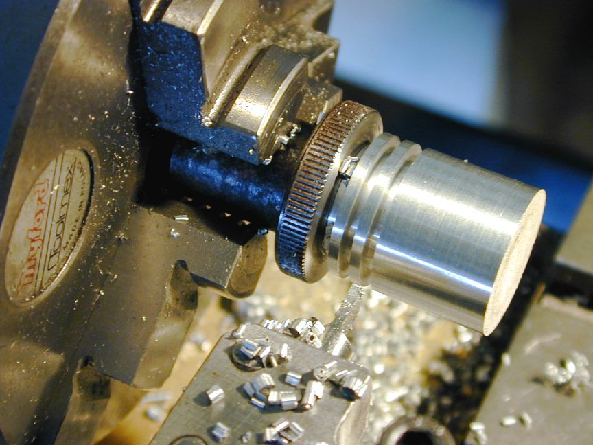
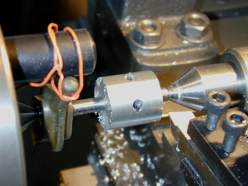
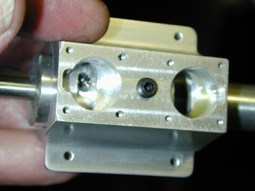
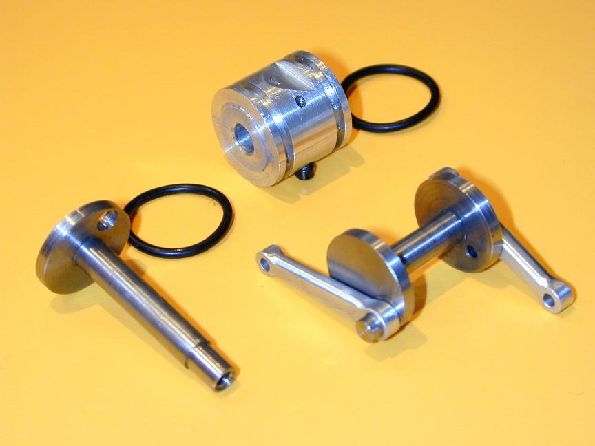
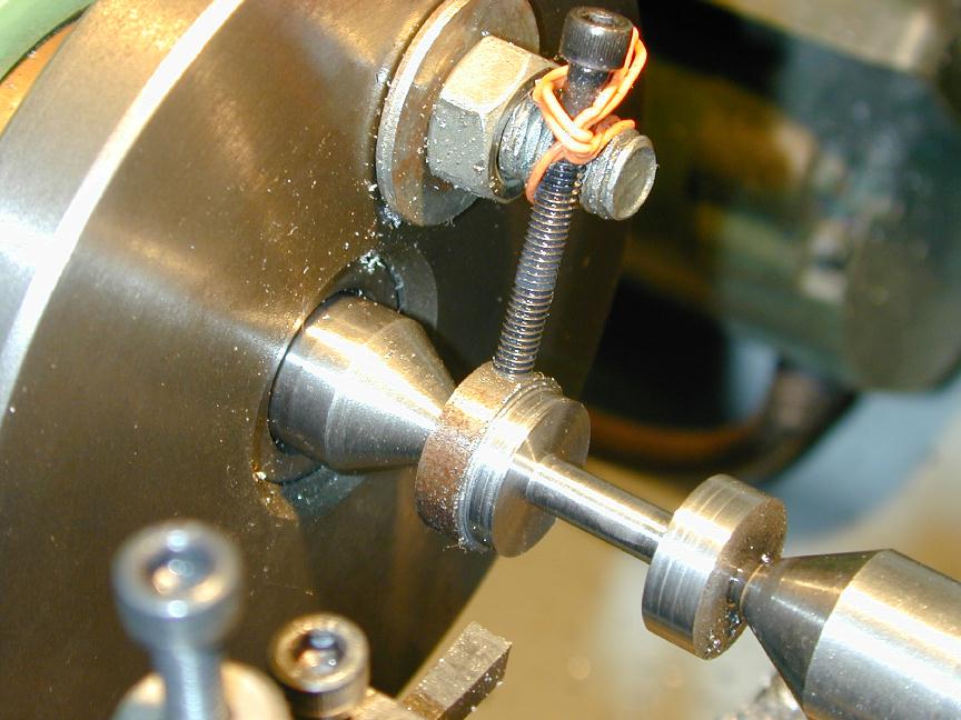
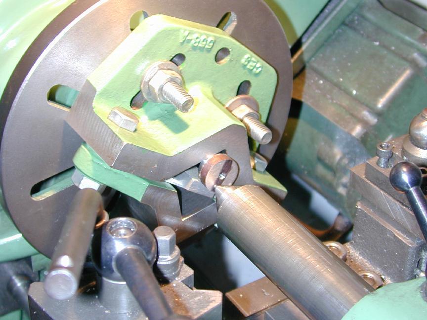
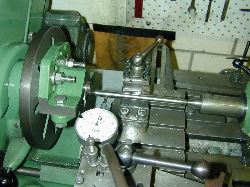
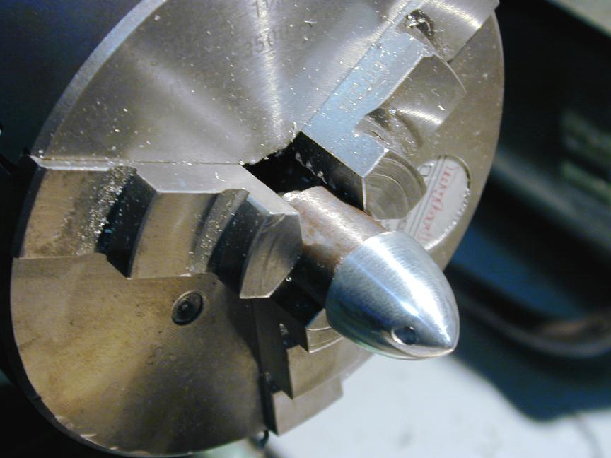
I figure the most important thing about the center bearing is that it holds the shaft aligned axially with the crankcase, which in turn places the cylinders at 90 degrees to the shaft axis. To achieve this, the bearing was glued (Lock-Tite) to a drill rod mandrel which had been carefully center drilled (in a lathe collet) at each end. This permits the bearing OD to be formed between centers. The big advantage of turning between centers is that the work can be removed and returned to the lathe as often as required with no appreciable loss of concentricity and no additional set-up. The next shots show the bearing OD being turned and carefully trial fitted into the case. The final picture shows the completed bearing with "O" Ring grooves and the inclined grub-screw seat (note theat Ken and I settled on two "O" Rings even though our drawing only shows one). The inclined seat is there for two reasons: first, it ensures that the dimple caused by tightening the grub-screw will not prevent disassembly. Second, the inclined seat tends to force the bearing forward against the internal seat (I stole this idea from the way the heads of shapers are generally fitted to their ram). This shot also shows the rest of the crankshaft bits, which can now be made.
 |
 |
 |
The center crankshaft was designed to have both the crankpins; the forward one being made longer to engage in the forward shaft. This makes assembly quite simple. I'll call this part the "bobbin" for historical reasons. It was turned between centers using a screw (8-32) tapped into the long (front pin) end as a lathe dog. This allowed me to work with a length of material that was almost to length and that simplifies follow-on operations. Note that the OD of the crank webs are also turned at this stage. It is important that these be concentric with the shaft and of precisely equal diameter because they will align the shaft while the pins are turned. Simple to do all this between centers as shown in the first photo of the next sequence. Note also the shape of the tool being used to form the shaft. It has a concave face with radiused points at either end. With carefull setup of the tool, this allows left/right traversals to accurately turn the shaft between the two crank webs.
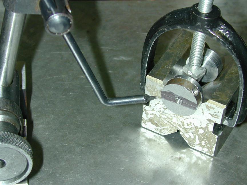
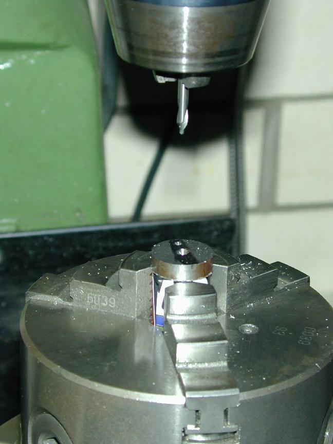
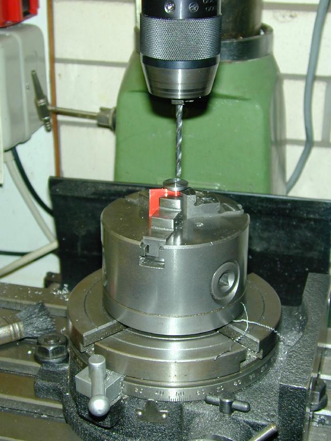
Next the bobbin is clamped lightly in a V block so an accurate centerline can be scribed on either end to ensure the crank pins are at 180 degrees to each other. The bobbin then goes into the 3 Jaw chuck, mounted on a rotary table under the mill. The chuck is centered, then offset by half the crank throw. With the bobbin in the chuck, the rotary table is rotated to pick up the scribe line. It can then be center drilled to locate the crank pin. This set-up will be left untouched so the bobbin can be returned to center drill the other end after the oversize area (caused by the drive dog screw) has been turned into the front crank pin.
To form the pin, the bobbin is held in a "Keats" angle plate mounted on a lathe faceplate. A dead center in the tailstock gives approximate alignment, followed by a wobbler and DTI to finalize the setting. This setting will be used on the other end as well, ensuring equal throw. All that's needed is to reverse the bobbin, then rotate it until the DTI and wobbler show that the crankpin mark is running true.
The front shaft is just a simple turning job as it has no crankpin. Finally it is returned to the rotary table under the mill to drill and ream for the crankpin driver as shown in the last photo of the next sequence. As that setup has not been moved, the alignment should be perfect, right? Well I don't believe in tooth faries either. On assembly, a slight but noticable drag could be felt at one point as the shaft was rotated. This corresponded to BDC for the front crank pin, suggesting the lineup was not perfect. There was no way to easily tell which way the hole needed to move, so I took a guess and gave a few strokes with a round needle fine towards the center of the shaft. On reassembly, the drag felt less, so it got a few more strokes. Repeat once more and the two shafts rotate as freely as a conventional single throw, one piece crankshaft. Perfect. Since I never make any "perfect" parts, I now needed to stuff it up in some way. My design called for a shallow, blind hole, tapped 4-40 in the center of the back web. This would allow a special tool to be inserted to pull the assembly out after the rear conrod had been removed. Guess who broke a tap in the hole? Right first time (bugger). Rather than make a new bobbin, I drilled a hole in the face of the back web, opposite the pin (you can see it in the exploded parts view). I probably should drill a coresponding balance hole in the front web, but I'm too ashamed.
 |
 |
 |
 |
 |
 |
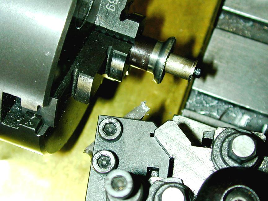
Prior to the judicious filing exercise just described, a prop driver and spinner had been made to turn the shaft with. These steps are hardly worth describing, but now that I've started... I've standardized on screw-in studs for my crankshafts. They're quick, easier, and stronger than conventional one-piece shafts (for the amatuer constructor) and may save a shaft from crash damage. The down side is they don't provide very good prop alignment. This can addressed by a step on the drive washer, or the spinner nut, or both. The next photo shows the rear of the spinner blank with a 3/16" spiggot that helps align the prop. The rear of the blank has been recessed with a 1/8" ball-end slot drill to remove a gramme or two (unimportant) and to concentrate the clamping force over a smaller area around the perimeter of the spinner nut. To the right is the jig that will support the spinner during profiling. The tommy-bar hole is drilled before finishing and the finished spinner appears next. Finally, we see the rear of the prop drive washer being profiled with a, well, profile tool (what else?). This shot also shows the well formed radial knurls I've finally managed to achieve with 100% consistancy (see the Weaver Articles and others for a complete description). My drivers have better knurling than many modern and old mass-produced drivers (he says, smugly).
 |
 |
 |
Another job being put off for a rainy day was cylinder joining. Again not difficult to do, just difficult to start doing! The distance between the cylinders when firmly bolted down was measured, then a piece of 1/4" square brass profiled against a 1/2" end mill until it's mimimum length matched this figure, minus a couple of thou (this to allow for tinning of ends and cylinder faces). If you look closely, you can see the cylinders are held down by nuts and studs which is more robust, even if more work than screws alone.
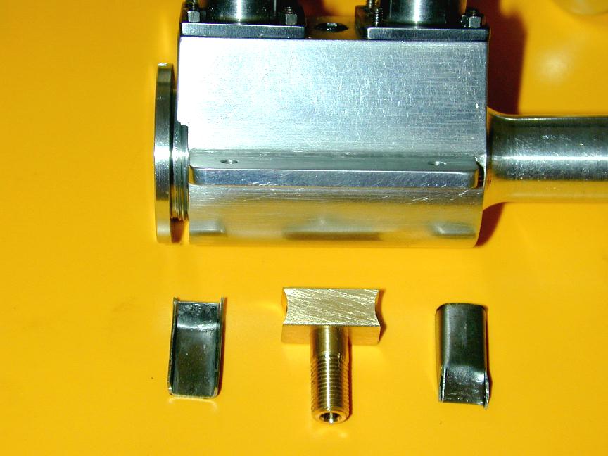
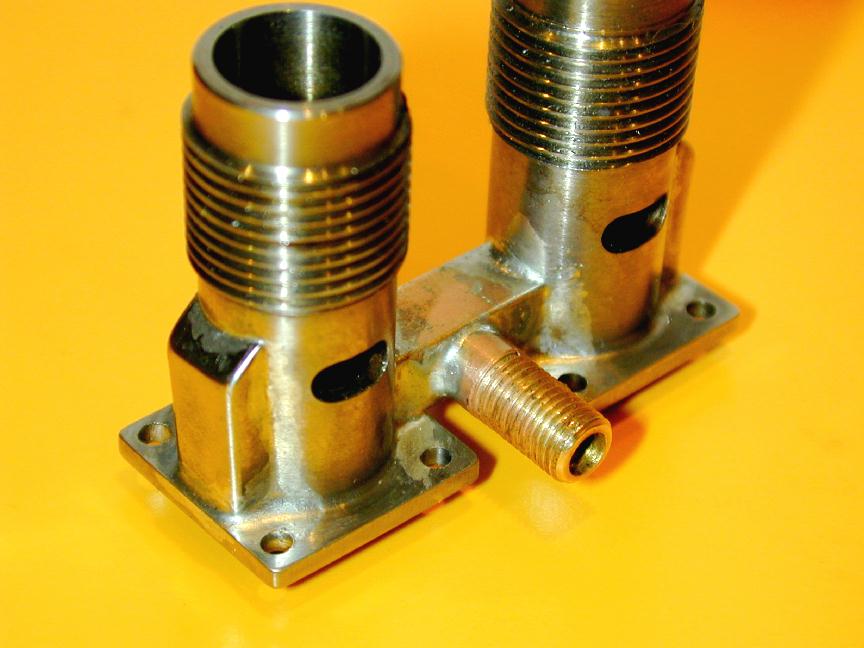
After a trail fit to make sure that the joiner piece was a close sliding fit, it was counter bored to take a threaded length of brass which will carry the venturi assembly. The stub was soldered in place and the ends tinned in one operation. The joiner assembly was then drilled between the profiled, tinned ends and the stub drilled to form the "T" inlet path. The next pair of photos show the parts before and after assembly. The bypass covers in the first picture have been bent to shape and appear amazingly "rough" in the shot. They are far neater in the next photo, although I now wish I had tinned all the square brass joiner rather than just the bits that mattered. Too late now though. For a complete and boring description of how I make bypass covers like this, see the Taplin Twin article and others...