Rotary Engines at The San Diego Air and Space Museum
![]()
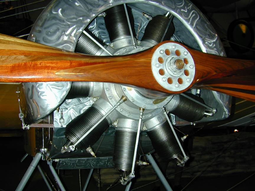
These pictures were taken at the San Diego Air and Space Museum in 1999. At the time, I was going through a rotary engine fixation (and I'm still not completely cured), with dreams of building a Chenery Gnome (I now have plans), or a Blackmore Bentley BR2 (I have the book). Hence, most of the shots center around the 7 and 9 cylinder Gnomes, with a few of the La Rhone.
These two were the most widely used engines during World War I. The major visible difference lies in the induction susyem. The La Rhone uses a "standard" induction pipe to a push-pull rod actuated valve, while the Gnome uses either a valve in the piston crown (which proved rather unreliable), or later, a single exhaust valve with inlet via a series of holes around the base of the cylinder, uncoverd at BDC rather like two-stroke practice, but not! This engine is refered to as the Monosupape, or single valve engine.
Another difference, not visible is the way the con rods are arranged. The Gnome uses the standard master/slave rod configuration, while the La Rhone uses a slipper arrangement with the big ends arranged in three tiers of concentric "shoes" that slip and slide on, in and over each other. This produces optimal timing at both top and bottom dead center, but is a nightmare to make and assemble. The master/slave rod arrangement, due to its geometry can never be completely correct (ie, provide equal timing spacing) at both TDC and BDC. Equal hole spacing is a compromise. Frequently the hole spacing was modified to provide better TDC spacing at the expense of BDC.
Incidentally, the Le Rohne is a two valve design, but is operated by a single push-pull rod. Note the double ended rocker arm that is able to push first one valve, then the other. Simple at the exposed end (although valve overlap is obviously impossible), but you should see the other end! The cam ring looks like an ink-blot and the cam followers which must track the ink-blot profile precisely are wonders of design ingenuity (and complexity), all to save a rod and a rocker -- although when said rods and rockers contribute to the gyroscopic effect, it may have made some kind of sense to the designers...
A final comment on the Gnome 7, then I'll shut up (promise): look at the cam housing where the tappets exit. Between each is a plugged hole. These were for a second set of tappets and rods when two 7's were joined into a 14 cylinder, dual bank rotary (now we're talking serious gyroscopic effect!) The Gnome cam is a single lobe design. To actuate the rods a number of cam rings are sandwiched at staggered orientation to provide the multilobe cam. Hence, each rod must be staggered fore-aft from its companions. If you look at the holes (14) in the cam box, you'll see how they follow a spiral pattern. We can assume that a 7 cylinder cam had spacers between each lobe segment. Incidentally, they were keyed to retain correct spacing -- imagine the effects of assembling that sandwich with a pair of segments in the wrong place 
 Gnome 7 |
 Gnome 7 cylinder |
 Gnome 9 cylinder |
 Gnome 9 |
 Gnome 9 in Fokker EIII |
 Gnome 7 plate |
 Gnome 9 plate |
 Gnome 9 sparking plug |
 Gnome 9 rocker |
 Gnome 9 tappet |
 Le Rohne 9 |
 LeRohne in Curtis Pusher |
 LeRohne in Fokker DRI |
 LeRohne rocker |
 LeRohne (side) |
![]()
 Home
Home
Back to Exhibitions, Museums and Shows
This page designed to look best when using anything but IE!
Please submit all questions and comments to
[email protected]