Building the SCHROEDER .09
Crankshaft and Other Parts
These instructions were originally written by Roger Schroeder
We are now going to construct the crankshaft plus some other miscellaneous parts. About now I can really appreciate the low cost of factory made engines. The time and effort required to make individual parts with limited facilities is tremendous. Our "store bought" engines are quite a bargain!
Crankshaft
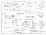
The crankshaft is a conventional design except that the crankpin is pressed into the crank web instead of being offset turned. This feature allows the fitting of a hardened crankpin into an unhardened shaft. I believe that the accuracy of alignment with this procedure will be as good as most offset turned operations and the two piece assembly is simpler. Smear a thin coat of epoxy resin on the end of the pin before pressing it into the crank web. The fuel admission port in the side of the shaft will be drilled later after all engine parts are made.
Note that a dimension is not given for the radial width of the counter balance. Mill the web to a .125" thickness until the counter weight step is tangent to the 11/64" diameter fuel passage in the center of the shaft.
The length of the shaft portion between the crankcase bearing is marked "to fit". Make this length appropriate to your crankcase which has already been constructed.
Connecting Rod
Select or cut a piece of aluminium stock that is 7/32" x 1/4" for the connecting rod. Locate and bore the .125" diameter and .187" diameter holes 0.900" apart. Next mill the center part of the rod to a 1/8" square cross-section. The end will have to be shaped by hand filing. Installing a big end bushing was covered in an Engine-uity article several years ago. For these that missed it, briefly the process is to turn some bar stock bronze to a .188" diameter and press the big end of the rod over the bar stock. Next drill and ream the .156" ID of the bushing. Finally cut off the bushing from the bar stock.
Drive Washer and Pin
The drawing for the drive washer needs little explanation. Round the edges of the flat that is cut on the .437" diameter so the timer cam will have a smooth side. Cut the knurl in the face using one roller of a standard knurling tool.
The drive washer is fixed to the shaft by the drive pin. A 1/16" diameter hole for the pin will be drilled in the crankshaft later when the engine is timed.
Sub-piston Retainer
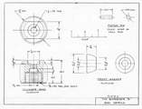
Make the sub-piston retainer first as a solid steel ring, then clamp it in a vice with part of the ring protruding. File away the protruding part until a 3/16" gap is obtained. WARNING! The ring is too fragile to mill the gap. I learned that the hard way (again!).
Front Washer
There is nothing special about the front washer except that it is made for the reproduction Arden 19 prop nut. Individuals may wish to alter the washer design to suit their own tastes.
Piston Pin
The piston pin can be hard or soft steel. A piece of 1/8" diameter music wire or drill rod steel can be used.
Cylinder Head
The cyl1nder head is also the cylinder cooling fins. Start making the head by boring and cutting the 5/8 x 40 threads .30" deep. Provide a relief at the end of the thread up to the .350" depth shown. The head gasket will occupy part of this relief area. Bore the 5/16" diameter cavity to a depth of 1/8". This cavity provides clearance for the V-2 spark plug electrodes. Do not drill and tap the spark plug threads at this time.
The shape of the head and the fin pattern is not defined on the drawing as this is left to individual preference. Only the top fin is specified because this is where a wrench must be applied to tighten the head.
On my first head, I cut .040" thick fins with a .040" spacing. The fins looked too heavy and I am in the process of making a second head with .020" or .025" thick fins with the same spacing.
After cutting the fins and shaping the head to a satisfactory contour, cut off the head from the bar stock. Turn the head around and chuck it in the lathe. Bore the 7/17" diameter x 9/64" deep cavity and then drill and tap the 1/4-32 spark plug threads. This will make the threads perpendicular to the floor of the cavity and allow a good seat for the plug gasket.
Partial Assembly
You will now have enough parts to make a partial engine assembly and test your bits. The first thing you will notice is that the top of the crankcase (the .50" diameter) will have to be filed out to provide clearance for the rod.
Check the position of the piston at bottom center in assembly with respect to the cylinder exhaust portl5. The cylinder base gasket thickness can be varied to adjust the relative position of the piston and cylinder. Also, a new .125 diameter hole for the piston pin can be bored in the sub piston if a major change in piston position is needed. This is what I had to do in order to adjust my piston position.
![]()

