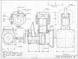
Building the SCHROEDER .09
First tooling operations and set-up
These instructions were originally written by Roger Schroeder
Design Presentation
This engine design shown in the General Arrangement drawing evolved from considerations discussed a series of articles that appeared in Engine Collectors' Journal. The basic objectives to be met by the design were:
- A spark ignition engine of 0.09 cuin displacement.
- A working engine with a reasonable power output for use in models—not a replica of any existing design.
- A project that can be accomplished in a home workshop using a metal lathe.
- A design that eliminates the need for castings and provides an alternate compression ignition design.
- Kept within the general dimensions of the Arden and Atom engine.
The design shown meets most of these objectives. The layout is mostly conventional, however a few unusual features will be pointed out in the detailed description that follows.
Starting at the front of the engine, the end of the crankshaft is stepped down to 3/16" diameter and threaded to accept an Arden type prop nut. The step-down is from 1/4" diameter and occurs at the front ball bearing. The prop drive washer (with integral cam) butts against the step-down and is secured to the shaft with a set screw or pin.
The BMC Motor Car points were just too big for use on this size engine. Therefore, Super Cyclone moving points and fixed points were selected. These were available from REMCO, Denver, Colorado in 1976. Today, you are on your own locating a replacement. Spare parts for a lawn mower might be pressed into service.
The contact point carrier is made from a piece of aluminium plate fitted with appropriate pins and blocks to support the points. The carrier rides on the front of the crankcase where it is located by a groove in the case. The front rotary valve venturi can be pressed or glued into the case. This eliminates the need for a case casting. The angle of the venturi does not improve performance; it is for looks only. As no suitable commercial needle valve could be found, a simple fabricated one will be shown.
The crankshaft is supported on two 1/4" bore by 5/8" OD ball bearings. The shaft need not be hardened. The 5/32" diameter crankpin is intended to be pressed into the crank web rather than offset turned as an integral part of the crank. This way, a hardened pin can be provided and the job simplified. The crankcase can be made from a piece of 1" square aluminium bar stock. The portion in front of the cylinder is turned round, as is the stub into which the cylinder is fitted. The remainder of the case can be left square, cut to the hex shape shown or filed to a round shape.
A steel cylinder is used which is screwed into the crankcase. Cox type by-pass porting is used in the cylinder walls. This is an efficient porting scheme and eliminates the need for the crankcase to extend up around the cylinder. Aluminium cylinder fins and cylinder head are designed as a single piece. The fins and head are screwed onto the cylinder and tightened by means of wrench flats provided at the top of the head. Clearance is provided for using the new REMCO C-1 spark plug because the V-3 type used in Ardens is very difficult to find. The exact profile of the cooling fins is left to the individual builder to allow custom variation in engine appearance between different builders.
In the side view of the engine, only portions of the piston are shown. One at the top of the stroke and the other at the bottom. Note that the bottom of the piston clears the exhaust port when at the top of the stroke. With the type of porting shown, a conventional piston pin must be positively locked in the piston by some means (clips, pins).
A free floating pin would eventually project into the ports and cause damage. The Cox engines have a ball and socket connection for the upper end of the rod which replaces a piston pin. This approach was considered too complicated and difficult for the home builder. Therefore, a sub-piston arrangement has been used to hold the piston pin. The sub-piston is simply a ring of aluminium 5/16" long with an OD fitting snugly into the piston. The 1/4" ID of the ring provides the rod clearance. A conventional wrist pin of 1/8" diameter is fitted to the sub-piston. The sub-piston, pin, and rod assembly are retained in the piston by a snap ring, similar to the method used in the Atom engine.
The connecting rod is made from steel and the lower end is bushed to reduce wear.
The design can be adapted for compression ignition by substituting a longer cylinder, a new head (with fins) and the addition of an adjustable contra-piston. These additional parts are shown in the rear view of the engine and will be detailed on the drawings. The rear of the crankcase is closed with a combination crankcase cover and combined fuel tank and mounting flange. I have designed and made two of these combination units, one for an Oliver Tiger and another for a 1/2A engine. They are lightweight, save space, and provide a good engine mounting. A Gitts cap type spring filler can be used if you can find one.
![]()
