![]()
Index
- INTRODUCTION
- BASIC EQUIPMENT NEEDS
- SKILL REQUIRED
- BUYING A LATHE
- LATHE ACCESSORIES
- MEASURING TOOLS
- MATERIALS
- PROJECTS
- REQUIREMENTS FOR RUNNING
- CLOSING
INTRODUCTION
To many of us, building our own model airplane engine has been a long sought goal. The idea that we can create a miniature engine that runs and produces useful power has a lot of attraction. However, many potential builders question if they can really do it. My answer is that, if I can build a decent engine and have it run, anyone can.
The following pages are based upon the engine building experience of my friends and me.
BASIC EQUIPMENT NEEDS
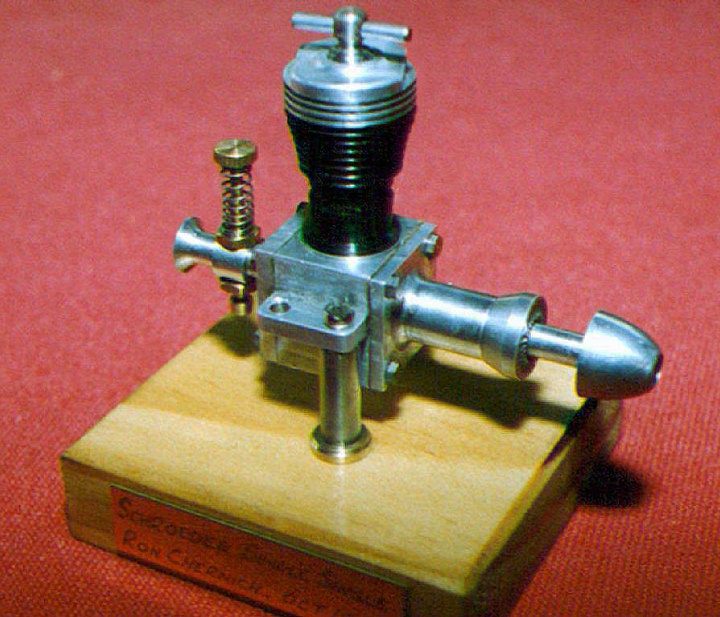
Now, to be practical, building your own engine does require a metal cutting lathe and some experience in running it. Not much else is required if you have a toolpost milling attachment for your lathe. My basic machine is a Logan 9 x 18 lathe with a Palmgren tool post milling attachment... My first engine was a Schroeder Twin which used "store bought" Cox pistons and cylinders to simplify the work. That was in 1965. Other more complicated projects followed and the Logan was sufficient to handle them all.SKILL REQUIRED
Skill is, first of all, an attitude of the mind that you can do it. You must place little priority on time and emphasizes the pride of doing a job to the best of your ability. With such a mind set you may spend an hour polishing a connecting rod just because you are proud of its appearance when you are finished. The skilled craftsman probably has a larger scrap pile than others, because he will not keep parts that represent less than he is capable of producing. The craftsman also knows how to get out of trouble, once it is encountered.Skill is also a learning process. The best way to learn is to start cutting metal. Begin with simple projects and go to more demanding work as you gain skill. You may scrap some parts along the way, but the time loss will be small compared to the learning rewards. You can't acquire skill by buying books. Books can provide ideas for things to try. You acquire skill by doing.
A book that provides at lot of good ideas about selecting a lathe, setting it up, and operating is, "The Amateur's Lathe" by L.H. Sparey. It is an English book published by:
TEE Publications
The Fosse, Fosse Way,
Nr Leamington Spa,
Warwickshire, CV31 1XN,
England
(see Suppliers Page)
Ron Chernich's web site is a valuable resource for model engine builders because it has a wealth of information on the pages. Recently Ron has reorganized the material and added a search engine to make it easy to find answers to your questions. Especially valuable is the new addition "How To". To find it, go to the web site at:
http://modelenginenews.org
There will be a menu on the left hand site; click on "Resources" and then click on the sub-menu "How To? "
BUYING A LATHE
What sort of lathe do you need? Don't settle for anything less than a lathe that can cut screw threads. If you can't cut threads, you are really limited in the projects you can try. American threads are fine now for those of us in the US. Metric threading capability is desirable. Try to get a set of change gears that will let you do bothAlso, buy a lathe with a 9 or 10" swing if your budget can stand it. Better a 9" or 10" used lathe in good condition than a 3" new lathe. However get someone with experience to help you evaluate used lathes. A worn and abused lathe will cost plenty to put into reasonable condition.
Used Lathes
I believe my Logan is an ideal home shop lathe. However, there are not many out there and the current owners are not prone to sell. The South Bend is an excellent choice. There are old South Bend lathes around in fair condition, but be careful of abused equipment. Do not buy a used lathe that does not have all the change gears or is incomplete in any way. It will be expensive to obtain the needed parts.There are also a lot of used Atlas and Sears Craftsman lathes out there. These are not as heavy as the Logan and South Bend lathes, but they are capable of good precision work as long as you do not try to take "heroic" cuts. Go for the older models made before 1980.
Other good used lathes are LeBlond, Sheldon, Harding, and the English Myford. Here we are talking about some expensive machinery.
Before you pay money for a used lathe, get your hands on it. Try shaking the spindle and all the slides. If you can move anything in a direction it should not go, cut your offering price a lot. The ways on a lathe bed contain an indelible record of the care the lathe has received. Read the record. If the ways have been abused, so has the rest of the lathe.
Also remember that the price of the new imported lathes puts a lid on the price of used lathes, assuming comparable equipment.
New Lathes
The oriental lathes are pretty good now and they are reasonably priced, however check all the specifications before you buy. Especially check the graduated feeds. Some are metric disguised as imperial. Talk to someone who has one. Enco is offering a small 6-in. imported lathe for about $1000 and a 7x10" mini-lathe for $500, or less on sale. For $2000 to $2500 you can get a 10 x 36 in. imported lathe with a certificate of tested accuracy. The English Myford lathes are some of the best.I am not impressed with combination lathe, drill and vertical mills that are being sold because I am not convinced that they can do all those different jobs well.
My good friend Randy Ryan has an oriental mini-lathe and a mini-mill. Here are his comments regarding them:
"The lathe is from Harbor Freight. It comes with a 3 jaw chuck (flange mounted) w/inside and outside jaws, a Jacobs type (way cheap but useable) tailstock chuck mounted on a tapered arbor and a live center. It has a turret type tool rest that indexes in 4 positions 90 degrees apart, 5/16 tools. It also comes with a set of change gears for cutting American threads and I think there is a metric set available. No rests but then being so short you hardly need them. It has solid state speed control with direct and backgear.
The only thing I wish was that it would run a little slower for threading, sometimes I have to engage the screw and roll it by hand, especially small female threads. Spindle will pass about 3/4" but the 3 jaw will only pass 5/8". It's also tapered and could be used with collets if you built up the drawbar etc. Can't remember the taper but can get it if you want. The spindle is mounted on deep groove ball bearings that are packed and sealed.
Little Machine Shop has all maintenance parts for it as well as a 14" bed and screw so you can expand it. I was going to do that but decided that I'd rather wait and get back into a larger machine.
The Harbor Freight mill is quite a bit less impressive that the lathe, though an experienced machine hand can make it work. It's terribly flexible and column squareness is questionable. I had to shim the column to get anywhere near in tram. Its now within about .001" over 4" in X & Y. Not the best, but since most of my work is about 1/2 that height, I can do pretty acceptable work on it.
It also has solid state speed control and back gear. #2 Morse in the spindle and only about 1 1/8 useful quill travel. The screw for quill feed is odd and the graduations are in .002 increments. It comes only with a chuck identical to the one that came with the lathe.
If I where to do it again I'd steer toward a larger more conventional machine. They have a pretty nice looking tiny universal knee mill but it's about $1400 before you buy a tool for it. All in all I get by with it, but it's not very pleasant to use. Little Machine Shop also has all the maintenance parts..."
Price is a fair indicator of quality and value. Shop the catalogs (see Suppliers: Tools and Tooling).
Go see it before you buy it, or talk to someone who has one. The manufacturer or dealer should be willing to provide a list of (satisfied only) owners. Take any negative comments seriously. The present owner will not be overly critical of his decision to purchase the lathe
LATHE ACCESSORIES
Just a bare lathe will not do much. You will need tool bits, boring bars, and holders for them. I like the carbide tipped cutting bits. They are already shaped and they last a long time. While you are at it, you will need to obtain a grinding wheel capable of handling carbide to bits. Free hand bit sharpening is very difficult. Buy or build a fixture that will hold your tool bits while you are forming and sharpening them. The one I built a few years ago has really improved my tool bits and, in turn, my surface finishes.Next, you need some drills and some chucks to hold the drills. Buy a Jacobs style tail stock chuck. Don't run out and buy a complete set of fractional, number, and letter drills all at once. Buy a modest set of the ordinary sizes first, and add more as required by your projects. Better the supplier pays for a tool inventory than you. The same for reamers, taps and dies.
We are not through yet. You need something to hold the work. A four jaw chuck is a necessity. Get a big one. Collets are nice, but you can build engines without them. A 5-in. three jaw, centering chuck is a very handy device and some of the import chucks are priced reasonably. I have a Chinese 5" chuck that centers within .002" TIR.
You can greatly expand the uses of your lathe with a milling attachment and I very much recommend one. Get the largest size Palmgren that will fit your lathe. They are expensive, but, trust me, you will never be sorry you shelled out the bucks for this one. You can buy a few end mills and also make some fly cutters. Now you have a lathe, a milling machine, a drilling machine, and a boring machine.
Buy set of center drills. Besides drilling lathe centers, use them to start every drilled hole. Twist drills wander a lot, and starting a hole with a center drill insures that the twist drill starts in the right place.
Don't invest in an expensive tool post grinder. You can finish pistons, cylinders and shafts better by lapping. You can adapt a Dremel motor to your tool post and/or milling attachment do light grinding and drilling.
MEASURING TOOLS
You must be able to measure the parts you make. Get a good 0 to 1 in. micrometer. Buy one that has a vernier that will let you estimate to .0001 in. or one of the electronic micrometers. The electronic micrometers are unbelievably accurate.Dial calipers are another must. They can be used where high precision is not required and are useful for dimensions greater than 1 in, measuring depths, and measuring inside diameters. The dial is much easier to read than the barrel of a mike.
You will need a dial indicator to center work in the chuck, check for tapers, detect out of round work, and measure crank pin offsets. Get one that has a 1 in. travel. Buy a magnetic base at the same time.
Get a set of telescoping gages for ID measurements. A mike, a dial caliper, a dial indicator, and a set of telescoping gages (all imported) can be bought for about $25 to $40 each and will be quite adequate for the home shop.
Initially for press fits and close running fits, you will machine, or lap, the mating parts to size by a cut and trial method. There is nothing wrong with cut and trial. Clock and watch makers have been working this way for 100 years. It just takes time and you may scrap a part now and then.
If you can afford more and better measuring instruments, you can machine your parts to fit quickly and skip all but the latter stages of cut and trial. I like Starrett measuring tools. I found you can buy good, used Starrett tools on eBay for about � the price of new ones. They are very accurate, and they hold their resale value, if you decide to take up golf instead.
MATERIALS
Almost as important as having a good lathe is the use of good material. Leaded steel stock is a joy to machine and well worth the investment. Model engine components do not usually have to be extra strong. Building a crankshaft from drill rod can be a real pain and a waste of time. Make it of leaded steel and case harden the high wear areas. I always case harden cam surfaces and drive washers. If you need a higher strength steel that does not need to be heat treated, get some "Stress Proof". Stress Proof machines very well and is really tough.For cylinders, I like the leaded steel, C12L14. So do a lot of the commercial engine manufacturers. For pistons, try leaded 4140 steel or Stress Proof. Some like a high grade of cast iron. If you intend to do a lot of running, use Stress Proof.
The 2024 Alloy aluminum is strong and easy to machine, especially if you squirt a little cutting fluid on it. Pure aluminum is not nice to machine. It comes off in hunks and tools tend to dig in. If you need to cut deep cooling fins in aluminum, buy some 2011-T3 free machining aluminum.
Free cutting brass, CA360, cuts like butter and will finish out beautifully. A few well finished brass components will make your engine look good and you even better.
Buy a can of Kasnit Surface Hardening Compound. With it, and a propane torch, you can harden the surface of mild steel parts like cams and drive washers. I have surface hardened pistons, but cleaning up the resulting distortion usually removes parts of the hard surface.
Good materials in small quantities can be mail ordered the Internet. See Suppliers Page: Materials.
PROJECTS
A simple glow or diesel engine will be a good first engine project. With these you don't need to worry about building a spark ignition system and making it workBe sure to visit the web site of Ron Chernich for engine pictures, descriptions, building and design help.
REQUIREMENTS FOR RUNNING
Assuming you have the tools and are starting a project, there are five principal requirements that you should keep in mind for making a two stroke cycle engine that runs. They are:- The parts of the engine must fit together and turn freely.
- There must be good cylinder compression
- There must be good crankcase compression
- The ignition system, spark, diesel, or glow, must be effective
- Fuel must be supplied to the engine
Each of these four rules are discussed in detail below.
1. The Parts Must Fit
It is easy to make a single engine part. It gets tougher to make two parts that fit together and run freely. I have a tendency to put things together with very little clearance. I am afraid that I will remove too much metal and spoil a part. As a result, I spend some time running in the parts to reduce friction. You must have to have the parts in the proper alignment. No amount of running in is going to help parts that are not aligned. You can avoid trouble by observing the following:- Get things lined up properly. The cylinder bore must be 90 deg. to the crankshaft bearing. The cylinder must also be centered over the crank pin. The crank main bearing and crank pin journals must be parallel. The rod bores must be parallel. Do not depend upon your eye to make cuts and bores in the proper alignment. Use the built in accuracy of your lathe and your measuring tools to get things machined in alignment. Watch out for tapered journals or bearings.
- Provide adequate running clearances. This is especially true for small engines. Make sure the rod is not rubbing on the crankcase interior. For crankshaft journal bearing engines, there must be .005 to .010 in. fore and aft clearance. Crankshaft bearings can have about .001 radial clearance. The same with connecting rods. The piston to cylinder fit must be closer, especially for a lapped fit. More on this fit in the discussion of rule No. 2.
- Avoid hand filing as much as possible. A round part does not stay round with filing, and a flat part will not stay flat. Sharpen your cutting tools as described in Sparey's book and your surfaces can be turned to size and finished with some emery paper, a good Arkansas stone, or by lapping.
2. Cylinder compression
Cylinder compression depends upon the seal between the piston and cylinder. Diesels must have a really good seal. Some builders prefer piston rings, but I like to lap the piston and cylinder because it is difficult to make small piston rings correctly. It is not difficult to make simple internal and external laps from aluminum, charge them with diamond compound, and lap the piston and cylinder. I machine the mating surfaces and leave about .001 to remove by lapping. The piston and the cylinder are lapped separately and only worked together at the last. Lapping goes quickly and results in pistons and bores that are straight, round, and have a really good finish. Buy 36 grit (fast lapping grade) diamond lapping compound from Enco or Travis Tool. A little lasts a very long time.The late George Aldrich convinced me to taper cylinder bores. The bottom should be from .0005 to .001 in. larger in dia. than the top (.0005 for � A engines). You simply spend more time lapping the bottom of a bore than the top to produce a tapered bore. Taper the piston about .0002 also. Tapering puts the closest fit at the top of the stroke were the combustion pressures are highest. The piston should just go tight (zero clearance) at the top of its travel. A tapered piston then fits like a keystone. The loose fit at the bottom will reduce friction and make the engine easier to start.
A taper is also a real advantage when fitting a piston. Finish the tapered bore first and then lap the piston until it will just enter the tapered bore. You then know that about another .0005 to .0010 in. of piston diameter reduction is necessary. Lap a little (10 sec.) and then try the piston in the bore. You can gage progress by cleaning both parts and determining how far the piston enters the bore. Quit lapping when the piston is a push fit at the top of the stroke. Before I started tapering the bores, I could not gage how the lapping was progressing and thus made a lot of pistons that were too small.
3. Crankcase Compression
Crankcase compression is as necessary as cylinder compression. Without it, the crankcase can not function as a pump to suck in fresh air and fuel, compress it, and force the mixture into the cylinder. An engine lacking crankcase compression will fire once but not consecutively.To test for crankcase compression, remove the head (and contra piston, if a diesel) from the engine and rotate the crankshaft slowly. You should feel the crankcase compression on the down stroke and hear a "poof" of air when the bypass port opens. You should feel a drag on the upstroke until the inlet port opens and then you should hear a "pop" when the port opens and air rushes into the crankcase. If you don't hear and feel all these things, find out why not.
The common causes of poor crankcase compression are leakage through, around, or between the following:
- A back plate gasket
- A crankshaft bearing that has too much clearance
- A loose fitting piston
- The inlet, exhaust and/or bypass ports
- The cylinder base gasket
- Too much cylinder taper
For those engines where the cylinder slips into the crankcase, the fit is very important because of the potential to leak between the ports. If this is a suspected problem, Bert Striegler showed me that it can easily be cured by smearing a thin coating of red RTV gasket material around the cylinder where it contacts the case. A thin coating of silicone grease will also do the trick and is not as messy as RTV.
To get the benefit of good crankcase compression, the port timing must be reasonable. Follow the dimensions for your design. As a check, for a piston ported engine, the following durations are conservative:
- Inlet 90 deg. (for piston porting)
- Exhaust 130 deg.
- Transfer 110 deg.
Shaft and disk rotary valves should open just as the exhaust closes and remain open until just after top center.
4. The ignition system
Diesel fuel will ignite if your fuel has a significant ether content and the engine has good cylinder compression. Ignition timing is controlled by the compression ratio which is adjusted by positioning the contra piston. A break-in diesel fuel will consist of the following:- One part castor oil
- One part ether (this is 25% ether; go to 35%, or more, for bores smaller than 1/2 in.)
- Two parts of No. 2 diesel fuel (truck fuel)
- (optional) 1-1/2 % hexyl nitrate to improve ignition
Ether is difficult or impossible to obtain. John Deere motor starting ether works for some engines; it has 70 to 80% ether. Get a spray can and put it in the deep freezer. When the can is cold, go outside, and spray the liquid ether into a suitable container. Be aware that not all motor starting ether has a high ether content.
Glow fuel will ignite if you have good cylinder compression, fresh commercial glow fuel with 10% or better (especially for small engines) nitro content, and a good glow plug connected to a battery that is delivering the full 1 1/2 volts. The compression ratio and nitro content controls the ignition timing. Gas/oil or alcohol/castor oil fuels will ignite with spark ignition if you have reasonable cylinder compression, a good spark plug, and an ignition system that will deliver 1/4 in. long sparks at all operating speeds. A typical ingition system wiring diagram is shown on Drawing "A".
Ignition timing is usually adjustable by rotating the timer assembly. For starting, ignition should occur at the top of the stroke. There should be about 30 deg. of advance available from that point. I use a 3 to 1 mixture of unleaded gasoline and 70 wt. oil with about 5 % ether added to give volatility. Alcohol base fuels run cooler and provide more power.
The critical element is the ignition points. There must be a lot of spring tension, or the points will bounce on the cam at running speed. The points must close and then open cleanly during each crank rotation. I have found that the time the points are together (dwell) before breaking is very important. The dwell should be at least 70 deg of crank rotation. If the dwell is too short, the engine may not 2-cycle well and it may not respond to a spark advance.
Tungsten tipped contact points have become difficult to find. Some builders have made points from tungsten welding rod material, but if you are not going to do a lot of running, hardened steel contact points will work well.
Model engine points that are designed like automotive ignition points have the best chance to succeed. Example are the McCoy, Hornet, OK, Super Cyclone, and Atwood Champion engines. These points have a rigid moving arm and a separate spring to close the points. Some timer designs combine the spring and the moving arm as one part. This can lead to trouble unless the spring action is well back at the fixed end of the moving arm and the arm does not flex in the middle. The Bunch engines had the combination spring and arm, and they always worked very well. If in doubt about your design, copy a design that works. The Hall effect, transistor-switched ignition systems work well on model engines.
A good spark plug is also required. For new spark plugs and ignition components, see Suppliers Page: Coils and Ignition Components.
5. Fuel must be supplied
The level in the fuel tank should be about 1/4 in. below the fuel delivery hole in the needle valve assembly. Bert Striegler tells me that the bleed hole should always be pointed toward the engine, unless you have two holes at 180 deg. to each other. In that case the holes should be cross-wise to the air flow.The tapered portion of the needle must be round and concentric with the needle shaft. If you use a spray bar, the needle should be a snug fit in the spray bar tube so that you suck fuel and not air.
The diameter of the intake tube at the needle valve (the venturi) is important. The venturi throat must be small enough to have a good fuel lift (a least an inch) at a low engine speed. If the venturi dia. is too small, the engine will have really good fuel suction, but it will be very sensitive to the needle valve setting. Conversely, a large venturi dia. will reduce the fuel suction and the engine will not be as sensitive to the needle valve setting, but if the engine (and fuel tank) is tilted while running, the fuel mixture setting will be upset and the engine may die. Look at the venturi size in commercial engines to estimate the correct size for your engine.
CLOSING
Building your own engine is a lot of fun and is a rewarding experience. Attention to the information described in the preceding will help you build a better engine.
![]()
Back to Roger Schroeder's Catalog

This page designed to look best when using anything but IE!
Please submit all questions and comments to
[email protected]