Here comes the miniature-DIESEL
IVAN ROGSTADIUS PRESENTS HIS SWEDISH BUILT ENGINE
This type of engine surpasses the common petrol engines of equal size when it comes to power, straight-forward design and reliable running. No preheating is needed in order to start it up. The high compression ratio alone suffices for ignition. Kerosene, petrol, ether, lubricating oil and paraffin oil are used in the fuel. The engine has extremely low fuel consumption.
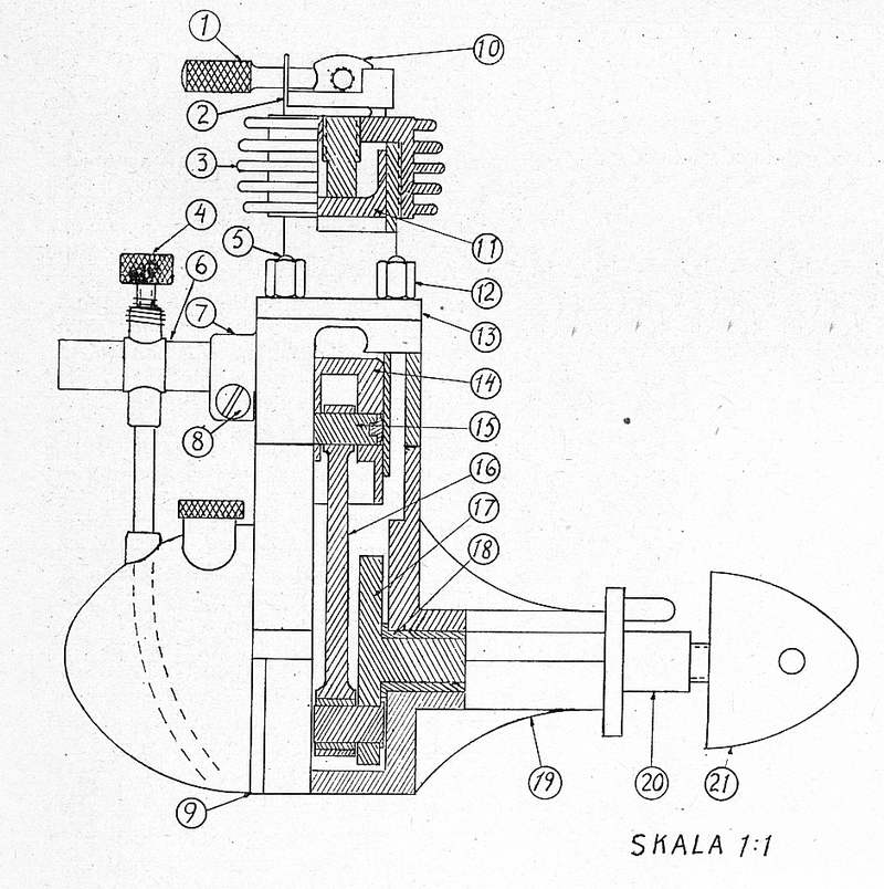
In order to achieve a good result, the construction of this engine must be carried out to the highest level of precision. The various components are:
- Compression adjusting lever
- Tensioning spring
- Cylinder head
- Carburetor needle
- Cylinder mounting stud
- Carburetor body
- Intermediate piece with carburettor boss
- Carburettor retaining screw
- Crankcase cover
- Compression screw
- Contra piston
- Cylinder retaining nut
- Cylinder
- Piston
- Gudgeon pin
- Connecting rod
- Crankshaft
- Phosphor bronze bushing
- Crankcase (aluminium)
- Propeller boss (steel)
- Spinner (aluminium)
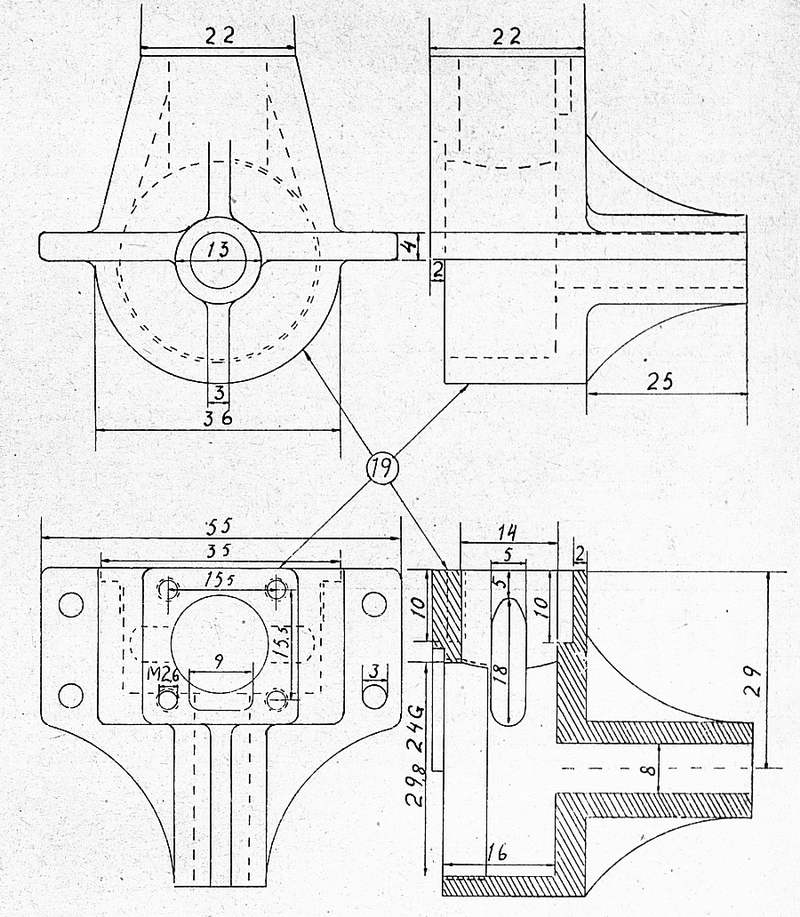
It is best to start construction with the crankcase, part 19. This may be cast or machined from the solid. When making a wooden pattern for casting, allowance must be made for shrinkage and machining, so that the final casting is not too small. The crankcase can be cast from aluminum, hiduminum or similar material. When turning and cutting in light alloys, red spirit is used for lubrication, so the metal won�t pick up. In the next issue of TfA, which will be out on Friday, January 7th, 1944, the last part of the description, including two more drawings, will be presented.
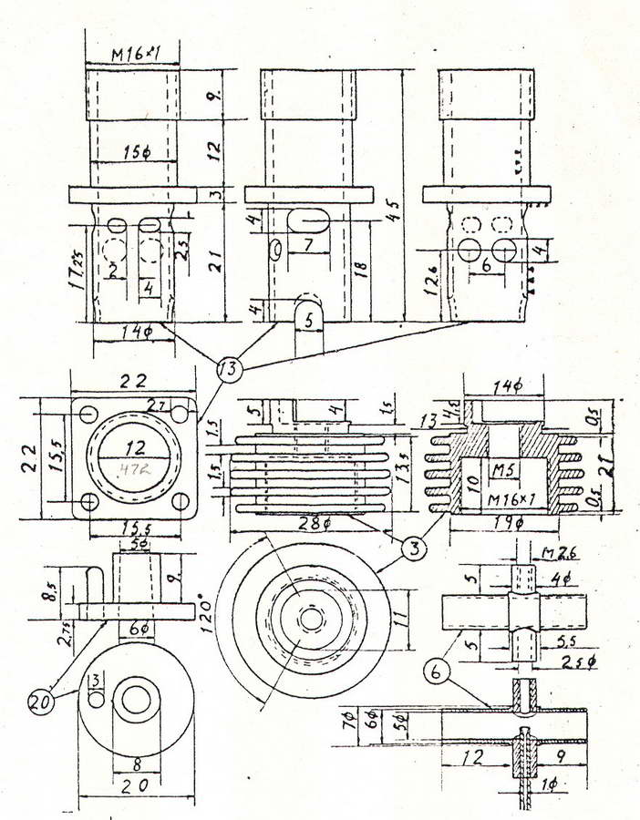
When the crankcase is finished, you should continue with the cylinder, part 13, which is turned from a steel such as Fagersta 14B4, which is suitable because it does not distort so much in the hardening process. When turning the cylinder, a 3/10 mm allowance for grinding is added where the triangles in the drawing indicate that grinding should be done. Great care should be taken when forming the ports, especially the height measurements. The exhaust ports, which are 7X4 mm, are located one on each side of the engine. The two ports that are 4X2.5 mm transfer the gas mixture from the crankcase to the upper part of the cylinder. Two more ports, 4 mm in diameter, pass the gas mixture from the carburetor to the crankcase and must therefore be located on the carburetor side of the engine.
Due to the long stroke of this engine, a couple of cutaways measuring 5X4 mm have to be made in the lower edge of the cylinder to provide clearance for the connecting rod. When filing these cutaways, also follow the dotted line on the inside. The cylinder is then hardened and tempered. For the grinding of the cylinder a hollow dowel is turned and a M16X1 mm thread is cut internally. The cylinder is screwed into this dowel, which can then be clamped in the lathe chuck for grinding. Due to the very thin walls of the cylinder it cannot be clamped directly in the chuck, because then it would not be round after the grinding. The tolerance for the inside grinding is 5/1000 mm, and therefore it must be done with utmost care, especially above the exhaust ports.
The piston, part 14, and the contra piston, part 11, are turned and finished in one piece. They are held together by a piece that is 5 mm long and has a diameter of 4 mm which is left when turning.
When hardening and grinding is finished, the piston and contra piston are cut apart. The outer diameter should be ground to 12.3 mm. When the piston is ground it is held in the chuck by the contra piston, and vice versa. The tolerance for piston fit in the barrel is 5/1000 mm. If after the grinding it sticks in the barrel, it should be polished until it just falls down the barrel by its own weight when the cylinder is absolutely clean and dry. The rounded shape in the piston crown is made at the center of the port from the crank case. The contra piston should have a rather tight fit in the barrel so it doesn�t follow the piston on its way down. if it did that, the engine would have no compression.
The cylinder head, part 3, is turned from aluminum, beginning with the inner diameter 15 mm, in which a thread is cut, M16X1. After that, the cooling fins on the outside are turned. A dowel should be made and the head threaded on for the final turning job.
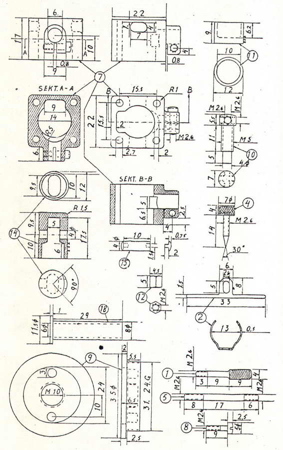
The intermediate piece, part 7, is made from aluminum. Make a hole in the work piece, 14 mm inner diameter and plane it. Mount the piece onto a 14 mm dowel for turning to get the height 17 mm and then do the rest of the work to shape the intermediate piece. The T-cut which can be seen inside across the hole for the carburetor connects the two 4 mm holes in the cylinder with the carburetor.
The compression adjusting lever, part 1, is turned from steel.
Part 2 is a spring that prevents the compression adjusting lever from changing position during running. It is made of steel sheet which is hardened and tempered to a bluish grey color, dipped in oil and heated once again to burn the oil off, a procedure that is repeated approximately five times in order to give the spring the required strength. It should be possible to work on it with a file after the hardening, otherwise it will snap when it is mounted.
Part 4, the carburetor needle, is turned from steel and the head drilled out in order to reduce weight.
Part 5, the cylinder mounting studs, are made from stainless steel, chrome nickel steel or screw iron, which is case hardened. Heavy bicycle spokes can also be used as stud material.
The carburetor body, part 6, is made of brass. Firstly, the horizontal and vertical tubes are made. A hole is drilled in the vertical tube to take the horizontal tube, which is installed and hard-soldered. The portion of the vertical tube that is inside the horizontal tube is then drilled out. Threads for the needle valve are cut in the carburetor, which then is nickel plated. A coil spring is wound and added to the carburetor so the needle valve doesn�t turn too easily. The seating for the fuel needle is shaped with a pointed spiral drill.
Part 8, carburetor mounting screw, is turned from steel and blue tempered.
Part 9, crankcase cover, is turned from aluminum. On the back side, two holes are drilled to fit a key with two pins in it. A hole is drilled and a thread is cut for mounting the fuel tank.
Part 10, the compression screw, is turned from steel and drilled out so that the compression adjusting lever can be threaded in from any one of four directions, after which it is hardened and tempered blue.
Part 12, cylinder retaining nuts, are made from steel or iron which is case-hardened.
Part 15, gudgeon pin, is turned from steel which is then hardened. A couple of brass studs are driven in to the ends to prevent damage to the cylinder bore. The gudgeon pin fit in the piston should be rather tight, but looser in the connecting rod. If the fit in the piston is too tight, the piston will become oval and stick in the barrel.
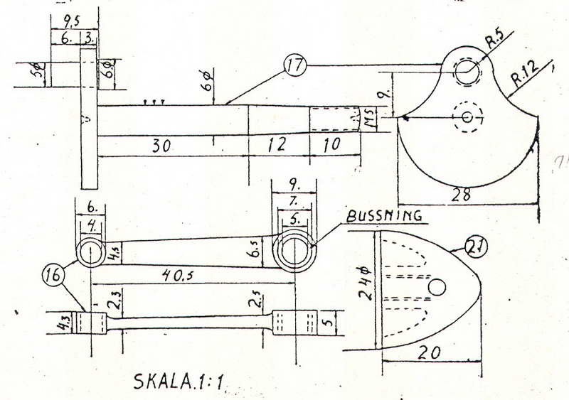
Part 16, connecting rod, is made from steel, hardened and tempered. The lower part is tempered blue and the bushing (which should be made of Nika or phosphor bronze) is pressed in.
Part 17, crankshaft, is turned from steel. A 3/10 mm allowance is added for grinding. The web for the crank pin is blue-tempered and the hardened steel crankpin is pressed in. The crank shaft is then ground to size.
Part 18, main bearing bushing, is turned from Nika or phosphor bronze and press-fitted into the crank case.
Part 20, propeller hub, is turned from steel and fitted to the tapered portion of the crank shaft. After hardening, a propeller driving pin is pressed into the hub.
Part 21, spinner, is turned from aluminum, and hollowed out to get it as light as possible.
The fuel tank, which in this case is made from a bicycle rear reflector, can be made according to your personal preference and ingenuity. The propeller is made from oak, ash or white beech. The recommended diameter is 270 mm, with recommended blade width being 25 mm at the widest point and the thickness at the hub being 13 mm.
Be careful to ensure that all threads fit properly without any play. If all sealing surfaces are carefully machined, no gaskets are needed. If necessary, thin paper can be used for gaskets.
Test running of the engine
The fuel consists of 60% kerosene, gasoline or petroleum spirit, 15% paraffin oil, 15% auto oil and 10% ether. The tank is filled with fuel, the needle valve is opened a couple of turns and the crankshaft is turned over a couple of times while the air inlet is covered with a finger. After this, the engine is started. If it does not fire, the compression setting is increased until it starts. Be careful at the outset and make only short test runs. When the engine is broken in, the paraffin oil and the engine oil can be reduced somewhat. This engine reaches 7,500 rpm and yields 1/10 HP.
 |
 |
![]()
