From the March 1967 issue of Model Airplane News
Tuned Pipes
A New Era In Speed
By Bill Wisniewski
This
is an article on tuning the exhaust gases in a miniature two-stroke
engine to produce an increase in power speed as well as effectively
decrease the noise level. I hope that the information in this article
can help further interest in speed as well as other events that put an
emphasis on speed and power.
When done properly, a tuned exhaust manifold can not produce at least a
10% increase in power output, but will make an excellent muffler,
reducing the noise level approximately 40%. This silencing action could
bring back some of the lost flying fields and the power increases could
make the silencer a popular item.
I have been working on exhaust tuning with Roger Theobald for the past
five years. The initial experiments prompted by conversations with Jack
Smith, a motorcycle enthusiast and old time model airplane enthusiast
were, therefore, patterned along motorcycle practice.
We have had quite a few problems along the road to success starting
from those first experiments. The first bench tests showed an immediate
improvement so they were encouraging. However, we were unable to realize
this gain in flight.
Progress was slow after these tests, but during late 1965 1966, prior
to the Con trol Line World Championships in England, work in this
direction was accelerated. Progress was made in two directions: first in
improving the dimensions of the exhaust pipe and, second, in developing
a technique which would let us realize the bench test potential in
flight.
The dimensions of the first pipes were taken using a typical motorcycle
proportions and scaling the length to model engine r.p.m. by using the
exhaust gas wave velocity corresponding to gasoline fuel. These figures
were found to be considerably higher than the correct one for alcohol.
In addition to the difference in fuel, model engine fuel is much higher
in oil content than that used in motorcycles, which also adds mass to
the exhaust gas.
By trial and error and with the help of thermocouple equipment, we were
able to measure the temperature along the length of a fairly successful
pipe and estimate the average velocity for our engines. It was
determined that the temperature is quite high (as high as 750oF)
and because of this, the exhaust pipe was insulated from the engine.
This insulation is a silicone rubber coupling and is cons tructed by
casting General Electric RTV-90 compound in a plastic mold which has
been machined to the same dimensions as the end of the pipe. The RTV‑90
coupling is bonded to the pipe by priming it with G.E. ss4004. Without
this treatment, the coupling will not adhere to the metal.
The temperature measurements and the lack of success in flight tests
led us to suspect that the pipe was cooling off a great deal in the air
and reducing the temperature of the exhaust gases. The reduced
temperature reduces the wave velocity in the exhaust and effectively
makes the pipe too long. The pipe was insulated with silicone rubber and
this modification was fairly successful. The F.A.I. model jumped in
speed from the low 140's to 150 m.p.h. Experiments. with various
coatings continued until the presently used black Sperex VHT exhaust
paint was tried. This coating resulted in the largest improvement in
efficiency and resulted in speeds around 160 m.p.h. with the F.A.I.
model on the standard 80-20 fuel ( i.e. no nitromethane)
A few words on the principle of exhaust tuning are in order. The engine
on the intake compression stroke pulls air and fuel into the crankcase
and also compresses the fuel and air in the cylinder. The power and
exhaust stroke is next. This is where we make use of the hot outgoing
gases to scavenge the cylinder and pull the excess fuel and air in the
crankcase through the engine, fill the cylinder and pull part of the
mixture into the headpipe of the exhaust system. Then the pressure
builds up in the pipe sending back a positive pressure just as the
transfer port closes and the exhaust port is still open, thus, pushing
the mixture in the headpipe back into the engine under positive pressure
giving a supercharging effect.
Now that the principle is known, we will have to design a pipe for an
engine. First, we must measure the volume in the crankcase with the
piston at bottom center. From practical experience, I have found that
the internal volume of the pipe should be about ten times the crankcase
volume and the headpipe cross sectional area should be 1.6 times the
exhaust port area. The next step is to find the length of the exhaust
system excluding the tailpipe length. This is done by picking a useful
RPM. This must be converted into time. To make it less complicated take
the RPM and reduce it to revolutions per second (cps) by dividing RPM by
60 then divide cps by 1 to get the amount of time for one cycle.;
1/(cps)
Then we must figure the percentage of exhaust opening less the overlap
or difference between the exhaust and transfer ports on the ups troke.
For example, if an engine has 170deg exhaust opening and 130deg transfer
opening, we have 40deg difference total then divided by two is 20deg .
170deg - 20deg = 150deg. Then divided by 360deg will give us the
required percentage. Let's call this number in the formula (P). Now we
must use a constant which is the speed of sound at the average exhaust
temperature in inches per second. Practical experience has come up with
22000 in/sec for our constant.
Then to reduce this to a half wave divide by 2 so the formula resolves
itself to
(P * 22000)/(2* c.p.s.)
For proportions see Figure 1..
These proportions are derived from experience also.
The tailpipe cross section area is 1/3 the cross section area of the
headpipe and the length is the intersection of the convergent cone plus
one diameter of the tailpipe.
Now to the engine: It must have no sub-piston induction, that is, at
top center there should be no gap showing under the piston. The reason
for this is that the pipe creates such a violent negative wave just
after the exhaust opens that at top center you are pulling some of the
crankcase charge into the pipe which leaves you with a very weak mixture
in the crankcase with a decrease in power rather than an increase. Also,
the more difference between the port heights on transfer and exhaust,
the more range of RPM you have. For example, 5deg overlap = 1000 RPM
range.
Construction of the pipe is not too difficult, but it is time
consuming. All the pipes used were machined from aluminum and magnesium
bar stock. A taper attachment for the lathe is handy, but not essential.
Here are the steps we followed.
1. Bore the inside diameter of the headpipe to about 2 inches deep.
Turn the outside diameter of the headpipe 1.5 inch in length. Thread the
end of 1/8 inch. We used a forty pitch thread on the headpipe so that
extensions can be made for varying conditions. Then turn a 1 inch
diameter x 1 inch length. Face to 42 % L + 3/32nds inch. (See
Figure 2.)
2. Reverse part hold on one inch diameter and bore press fit diameter
for mating part 3/32 inch deep. Bore major inside diameter 1/8in deeper
than press fit diameter. Set taper with a dial indicator. Bore taper
blending at major inside diameter. (See Figure 3.)
3. Make a plug to fit the major inside diameter of pipe as shown in
Figure 3. Hold on the headpipe with the plug in the end supported by a
live center. Turn the outside taper to a .016 in, wall thickness. Then
turn major outside diameter to major inside diameter plus .050. Blend
outside taper to the headpipe. (See Figure 4.)
4. Make rear cone using the same procedure as the front cone except as
shown in Figure 5.
5. Bond the two cones together using a good high temperature adhesive
at the press fit joint.
The engine which was used in the World Champs and which has had the
bulk of the development effort is a special engine of our own design
which also uses some K&B 15 R components. During the past few months,
however, we have been testing these systems on standard K&B engines with
very gratifying results. We have gained up to 1500 rpm with no other
change to the engine other than adding a tuned exhaust pipe. Experiments
with raising the exhaust port are still going on, but could yield a
further performance increase.
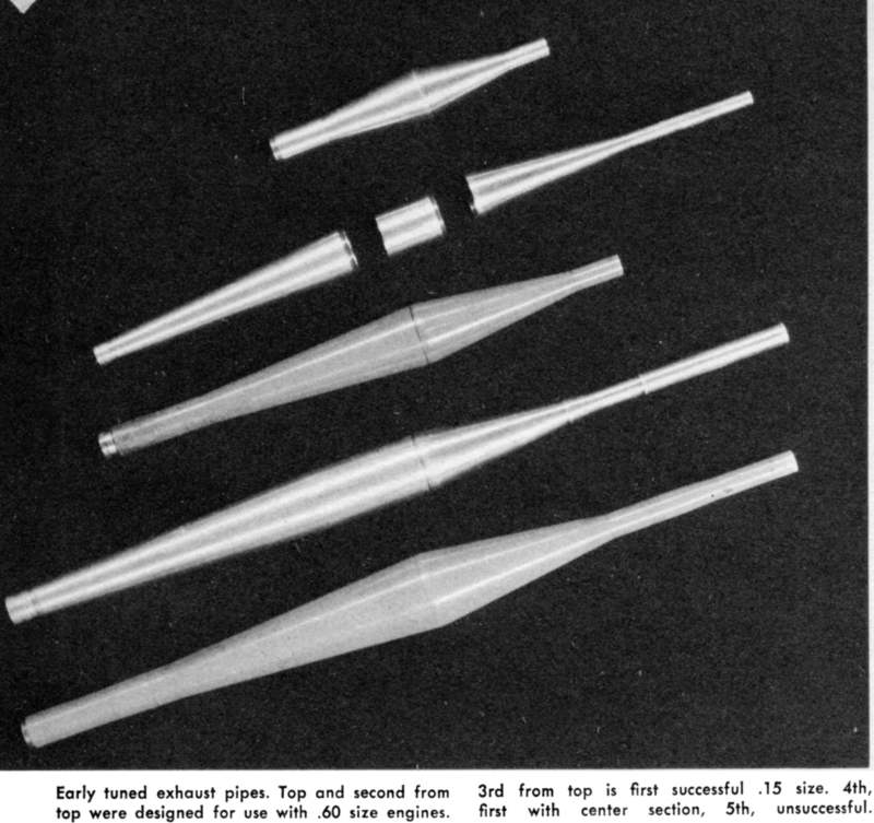
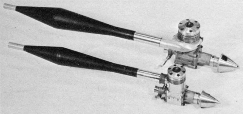
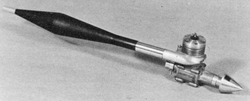
The photos show Experimental Pipes
the World Champs
engine and and 29 R for comparison
TWA and 29R
and the experimental KB 29 R
I believe that the tuned exhaust system can work on anysize of engine
although there is a lot of development work for each new application.
The tuned engine exhaust seems to have no effect whatever on the engine.
We had 30 to 40 high-speed flights on each engine with no apparent wear
at all. Fuel consumption is approximately 10% than normal even though
the power output is increased considerably. We have gotten as many as
twenty and never less than five flights per glow plug.
The engines are not hard to start adjusting the needle valve is quite
different due to the garbled exhaust and reduction in noise. Once it is
set however it does not have to be changed with each flight. There seems
to be some controversy about the tuned exhaust system. The tuned
exhaust is not a startling new concept. It has been used for a good
years in several racing sports. Indianapolis racers, motorcycles, sports
cars all use some form of exhaust tuning. Roger and I have merely
applied a 30 year-old physics principle to model aeronautics.
True, this is not immediately available on the commercial market, but
this has not stopped modelers before. They have a knack of turning the
difficult task into an accomplished fact. This is where we progress in
our sport.
Of course, you can go faster by using so called super fuels. Most of
these fuel ingredients are prohibitive in cost as well as being
difficult to obtain. If not handled with ex treme care, they can be very
dangerous to your health .
In this article, I have tried pass on to you modelers the benefit of
our six years of work and study. All construction details are given so
that those who do not have the facilities to do the work may have
someone else make it.
Most important, let us keep an open mind and not regress to the past,
rather progress to the future.
|