Peter Burford's Miniature Diesel
 Some people retire, then decide what to do with their sudden increase in spare time. Master machinist and die maker, Peter Burford, knew what he wanted to do, but realized he'd have to retire to do it right—you gotta admire that kind of style! Peter's father is the Australian model engine icon, Gordon Burford, designer and manufacturer of the Taipan, Glow Chief, Gee Bee, GB, Sabre, Stunt-Mota, etc ranges of engines. The story of Gordon's life-long passion has been told in a number of publications. Perhaps the best of these was a series of six articles by Ivor F that appeared in Model Engine Word beginning with Volume 4, Issue 4, Number 40 of August 1977. Omitted from the tale is the fact that Gordon was joined by son Peter in the 60's, initially as an apprentice machinist, ultimately as manager of the plant up until Taipan called it a day. Even after that, while Peter was operating a die making and injection moulding business on Australia's Gold Coast, he watched his father's small production run engines (like the Burford Deezil, CIE, original Sabre 2.5, etc) and must have thought it all looked like fun.
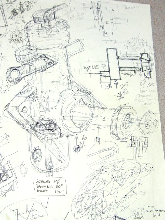 Peter says he is not a modeller, though with Gordon for a father, it was unavoidable for him not to fly small control-liners and other types while growing up. But he does have a modeller's passion for small engines and even though he had been part of the decision that saw Taipan cease manufacture, he retained both the interest and suppressed desire to build an engine that would not have to compromise quality for cost. He is also a meticulous worker and clinically neat in his approach to his work (Vincent Chai who accompanied me for the visit with Peter is a GP and observed whimsically that he wished our hospitals were kept as clean as Peter keeps his workshop). The picture here is Peter's original sketch for the 0.33 dated April 3, 1995. The engine was drawn as a side-port with a crown-wheel compression screw, but the general layout is very close to the final product that would not appear for another 9 years.
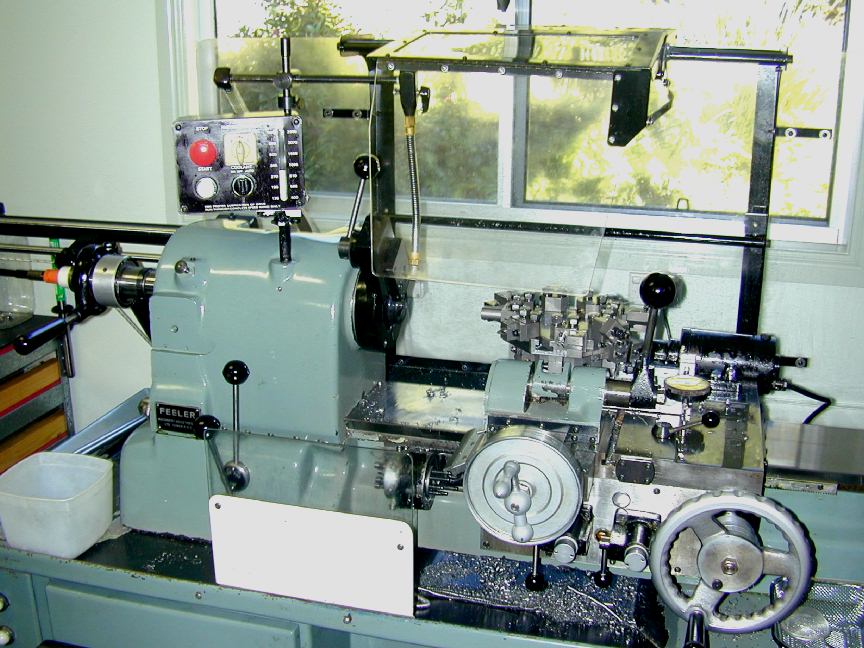
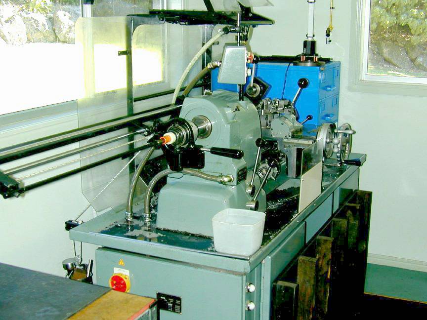
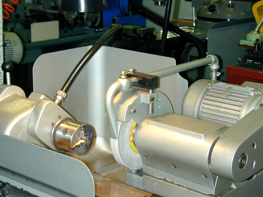
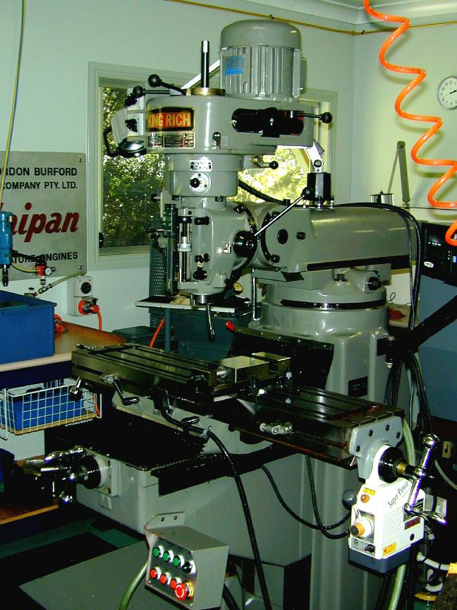
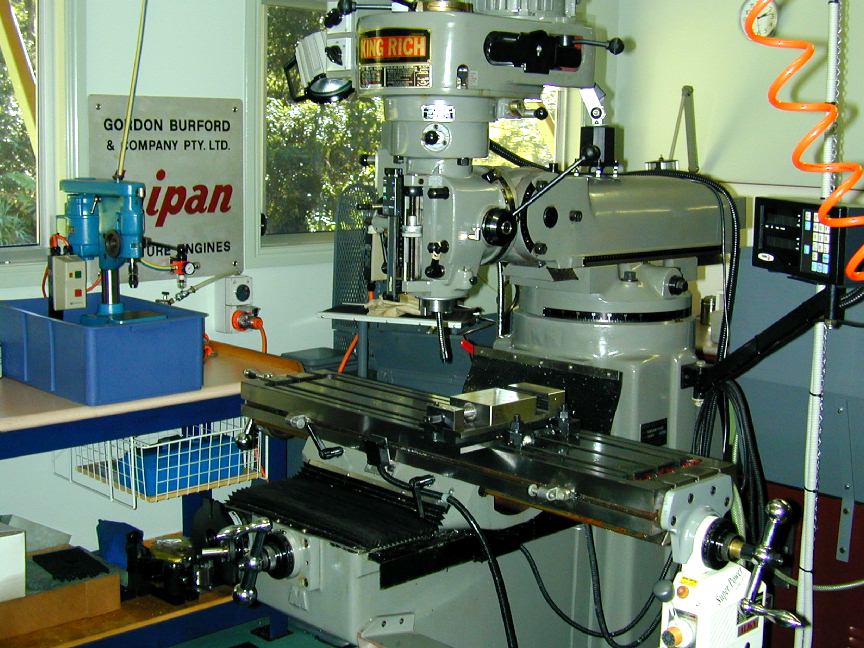
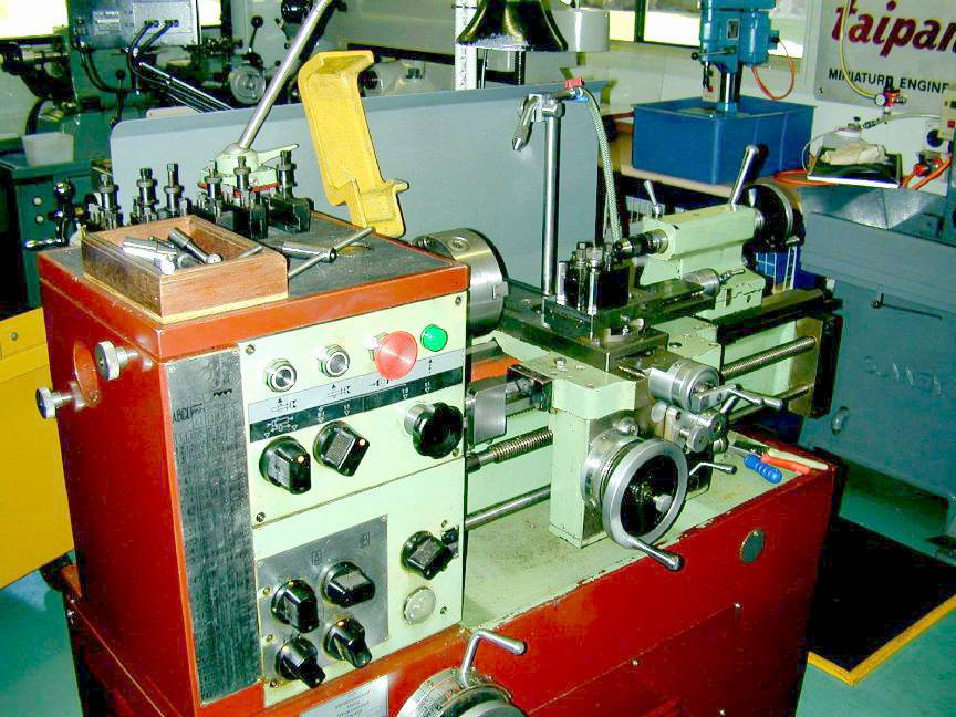
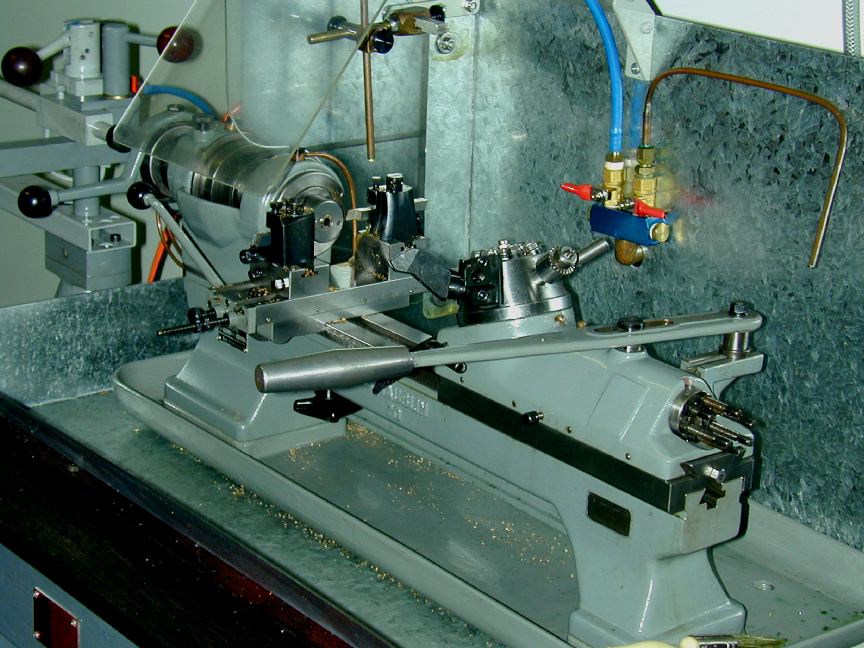
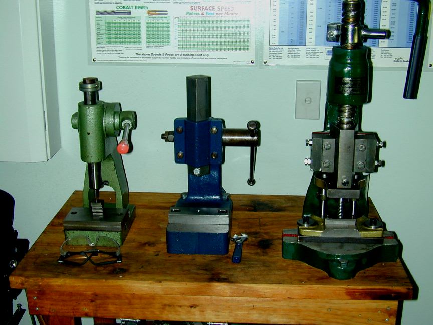
Where to start describing Peter's shop? First, it's roomy, with large glass windows around two sides that provide great natural lighting from Peter's garden that abruptly changes to bushland, being situated just below the crest of what Ozzies would call a mountain range and other would call hills. In the center of the shop is a cluster comprising mill, tool-room lathe, external grinder, and surface grinder. Grouped around this cluster are two turret lathes: a Swiss Schaublin 70 (Peter's favourite), and a Feeler (which is a good copy of a Hardinge), plus benches, press tools, Sunnen precision hone, and precision drilling machines. An assembly station, come design bench, and generous storage facilities completes the picture. Compressed air is delivered to the machines needing it (like the feed mechanism on the small turret lathe). In fine attention to detail, the air lines are painted yellow with oil/water traps at all outlets. The pictures below show some of the machines.
|
|
|
|
|
|
|
|
|
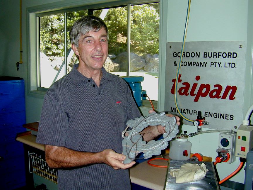
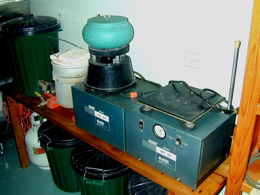
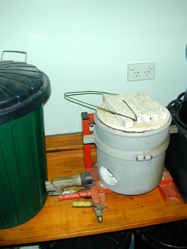
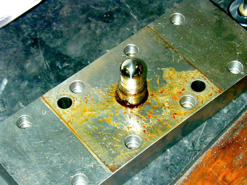
Beside the machine shop is a room that houses the compressor and the lost-wax equipment. Peter does all his own investment die casting using the equipment in the photos below. The casting process is vacuum assisted, depending on the slight porosity of the investment to draw the melt into all the intricate cavities of the case. Peter says this also assists in the removal of air bubbles from the castings. His furnace is gas fired and quite basic, though the pyrometric equipment that he brings to bear on the process, and on the subsequent heat treat process is anything but basic. Still, errors do happen. The odd object d'art being held by Peter here is a cluster of crankcases that got heat-treated at a somewhat high temperature due to a faulty thermo-couple.. Like all craftsmen, Peter keeps such things around to remind himself that bad things happen to the best of us (you should see my reminders!).
|
|
|
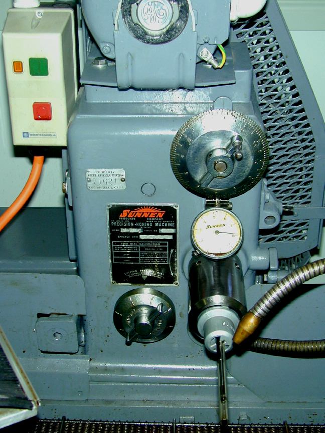
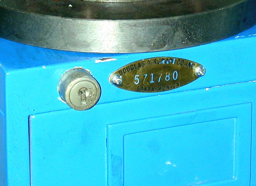
Peter is proud of the provenance of several pieces of workshop equipment, much of it bought from used machinery merchants and expertly refurbished by himself. For instance, his Sunnen hone seen here bears a plate proudly bearing the name North American Aviation. He has no idea what purpose if served in their plant, but that does not really matter; just the fact that it served some purpose within such a hallowed name is sufficient. In another aircraft manufacturing connection, a file cabinet has a Douglas Aircraft Corp plaque rivited to its corner.
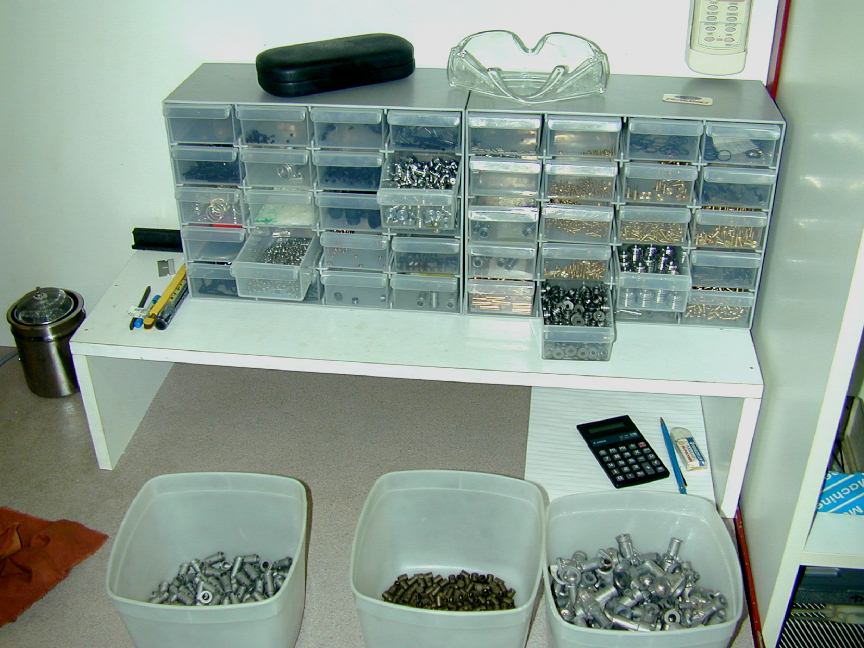 The engine was designed with CAD, and all tolerances worked out so that no "mix and match" assembly would be required—even when all tolerances stack up the wrong way, Peter is confident that the engine will still perform to specification (even so, all engines are test run by Peter before packing and shipping). The photo here shows the parts bins for the first production run of approximately 147 engines. The final production number may be far higher as sufficient material and specialized tooling (like taps etc) have been stockpiled to permit some 3,000 engines to be built.
Even though I've read fairly extensively on sand and die casting, including Bruce Satra's terrific series in SIC on making the head die for the Morton M5, and discussed the processes involved with experienced folk, it's all a bit of a black art to me. Basically, the die must produce a wax replica of the case which can then be potted (invested?) in a material able to take the stress of molten metal. When this stuff sets, the wax is melted out to make room for the metal (this is a special wax that leaves no residue—some use a centrifugal table to help get the molten wax out). Since making the wax "positive" is a gentle process, the die can be aluminium which is easier and cheaper to machine than the steel die that would be required if it were to take the molten metal direct. Regardless, the die must be made so that the cast object can be removed. This means that any protuberances into the wax must be designed so they can slide out, somehow.
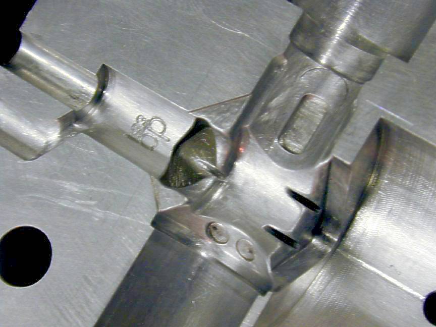
These shots show a close-up of the venturi side of the die, and how the three plugs will sit in their openings. In the left-most, notice the channel below the opening that will support the front of the bore plug. This provides the sprue through which the wax will be injected. This sprue is retained and joined to a spider permitting five cases to be invested together, and finally, provides the entry for the molten aluminium. The shot on the right shows how the plugs enter the die cavity. The Schnurle boost port is uppermost on the cylinder plug and the split lines marking the slide-in piece that permits the plug to slide out independent of the port piece is visible, if you look closely enough.
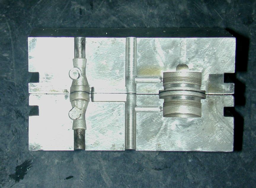
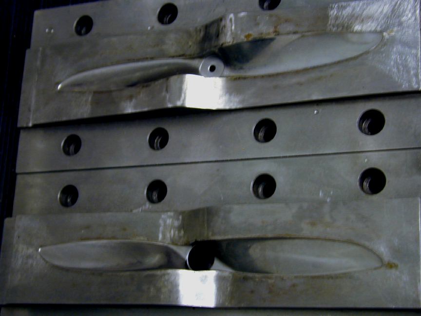
More of the die maker's art. Above, from the left are the die for the fuel tank, the combined venturi and backplate, and on the right, the die for one of the pair of very elegant propellers Peter designed for the 0.33. The prop bears a strong resemblance to the Taipan range of props with wide cuffs reminiscent of the "Larabee" blade form (designed for the highest possible efficiency at the lowest possible speed). Obviously the prop die must separate around the periphery of the blade shape, but what happened in the middle? If you examine commercially moulded props, you can gauge the quality of the dies by how the lower trailing edge meets the higher leading edge of the opposite blade across the side of the hub. Many are a simple vertical step (including the Taipan props of yore). Not infrequently, this will leave a step, or a flash on the prop. Peter wanted his props to be as blemish free as possible, so notice how the TE sweeps elegantly up to the LE. The result is a very attractive and blemish free job. The "roughness" visible at the tip of the die faces is intentional. This provides sufficient passage for air to escape as the glass reinforced polyamide flows in.
Aside: What's the difference between a "jig" and a "fixture"? According to Franklin D Jones, Jig and Fixture Design, The industrial Press, 1942, a jig is a special tool, that while it holds onto the work, also contains guides for the respective tools to be used, while a fixture only holds the work while cutting tools perform the operation on the piece without any special arrangements for guiding these tools. The fixture therefore must be securely held ("fixed") to the machine on which the operation is being performed—hence the name. End of aside.
What I don't have a photo of are the 40 little blocks of tool steel, fully hardened, all ground perfectly square and within less that 0.001" of each other in all dimensions. In production, these each mount a crankcase on a spigot that locates in the backplate opening—boring this to size being the first machining operation on the case. With 40 cases mounted on 40 blocks, the cases can easily be moved from jig to jig for subsequent operations. The jigs clamp the blocks which reduces setup time and assures high accuracy. More overtime work for the surface grinder making them, but it all makes sense to me. Screwing and unscrewing little cap-head screws to remount cases on the different jigs would be a pain, and leave unsightly marks on pristine cases as well.
Ron Chernich, Brisbane, May 15, 2004.
Back to Model Engine News Home Page Please submit all questions and comments to Enquiries at modelenginenews.org
 The PB .33 is a Schnurle port, front rotary valve induction, compression ignition engine of 0.33cc (.020 cuin) capacity. All steel parts are fully hardened steel and ground to very, very precise sizes. In a departure from the normal, the piston is hardened steel instead of the usual cast-iron. This "hard-on-hard" design means that the "pinch" of liner on piston at TDC is very light, so compression is achieved by grinding piston and liner to very precise size and a high degree of circularity. Does it work? Well the engines run, and run well and the piston and liner I examined felt silky smooth in operation and my fingers got sore pushing on the con-rod end holding the piston pressed against compression with no sign of the pressure leaking away. I wish I could say that of some of my own work.
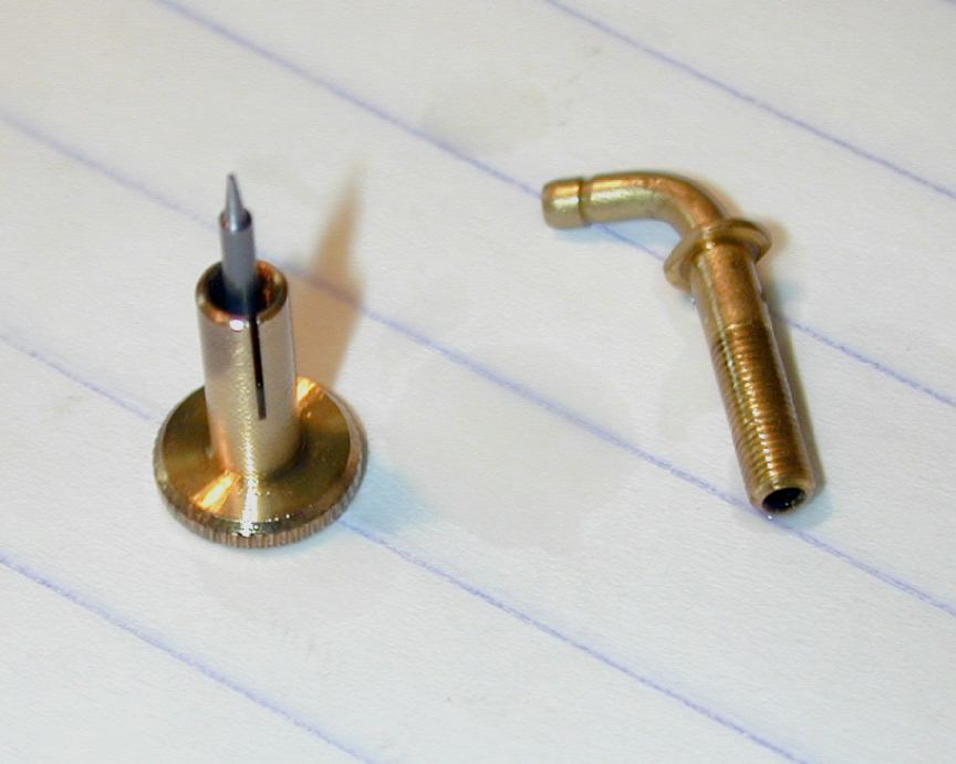 After chatting with Peter for a few hours and examining the engine, I wanted to call it a "no compromise" product. Peter would not have it, saying everything is a series of compromises. Maybe so, but look at the needle. It is ground from 3/64" music wire on the same center grinder that grinds shafts and pistons. The needle is just long enough to meter through the jets, then quickly steps out to full diameter to minimise the possibility of air leakage. The needle is pressed into a split thimble with such accuracy that there is no sign of binding as it is screwed into the spray bar. The very tip of the needle is not sharp, nor flat, but carefully rounded. The top of the brass thimble has a little circular depression as an indexing mark. This is not cone-shaped, as it would be if touched with a drill bit, but spherical for no other reason than pure attention to detail. Think I'll stick with my no-compromise theory.
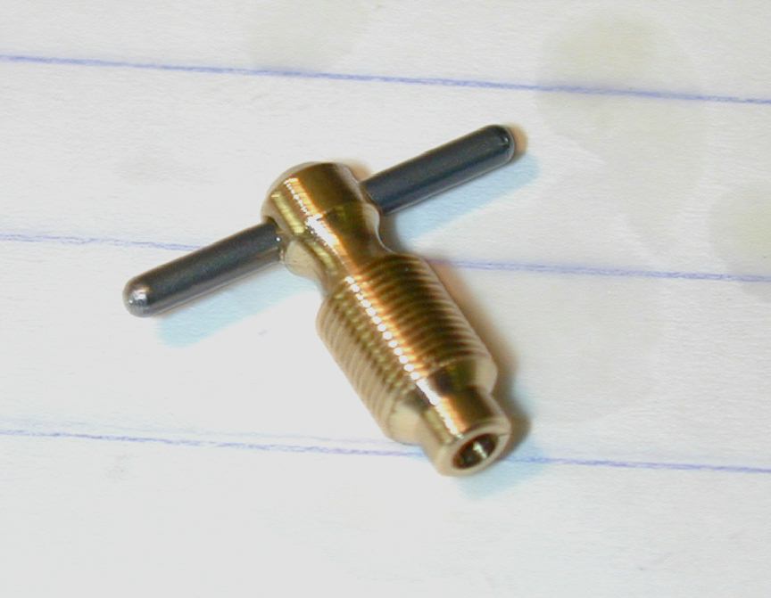 The compression screw is brass, with a fine thread and comparatively large diameter to give a very pleasant "feel". Notice the hollow point. Years of experience with Taipan led to this little touch (and one I first heard from David Owen and have mentioned in these pages before). The center of the contra-piston will probably be slightly raised. So would the tip of a "flat" comp-screw end. The result of these two not-quite flat surfaces registering against each other is a comp-screw that will unscrew under vibration every time. The hollow point allows any slight pip on the contra-piston center to be compensated for, reducing the likelyhood of it unscrewing while the engine is running. As a further precaution, a nylon screw in the cooling head gives a bit more friction and a nice feel. Have another look at the full size photo, paying special attention to the tomy-bar ends. The tommy-bar is 1/16" music wire, with the ends ground spherical on special tooling built by Peter. Not only does this look good, it assists the press fit and provides a nice operator feel.
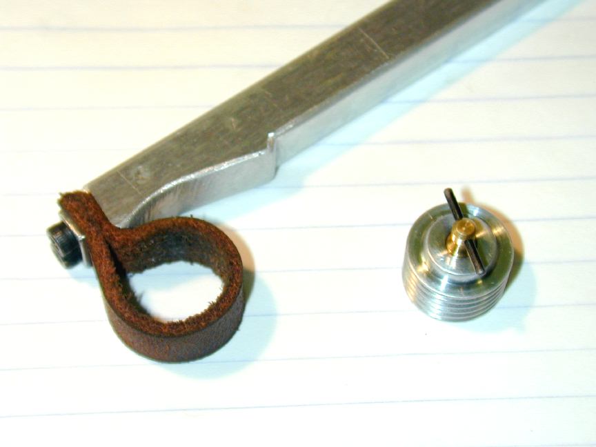 This shot shows the cooling head and the simple tool that is used to tighten it up. Not easily visible is the 2-56 nylon grub-screw in the step above the last cooling fin that provides extra friction on the com-screw as mentioned earlier. Surprisingly, all threads on the engine are imperial—a fact that will probably be appreciated by US owners.
 Here is the hardened mild steel steel piston and EN36A nickel steel crankshaft. Just visible if you know where to look is the Schnurle boost transfer port in the piston. This scheme has the theoretical advantage of assuring a flow of relatively cool mixture through the piston during transfer that helps keep the temperature down and assures lubrication of the wrist pin. The wrist pin is just about the only thing on the engine that Peter does not make, rather it is a hardened steel roller. It is pressed into the conrod and freely rotates in the piston. There are light counterbores on the piston wrist pin holes that serve dual purposes. They align the piston in the tooling used while the pin is being inserted, and act as little oil damns to assist lubrication. As we'll see later, the pin insertion tool ensures that there is no possibility of the wrist pin and cylinder liner ever coming into contact with each other. Very cunning. Now look closely at the end of the crankpin. With the pressed in wrist pin and tall crankcase geometry, jiggling the conrod onto the crankpin would be nearly impossible. The little bevel on the pin allows the rod to be rocked easily onto the pin with the shaft at the TDC position. The amount of bearing surface lost is miniscule, and who knows, it may act as an oil reservoir as well. I must remember this trick next time I make more AHCs!
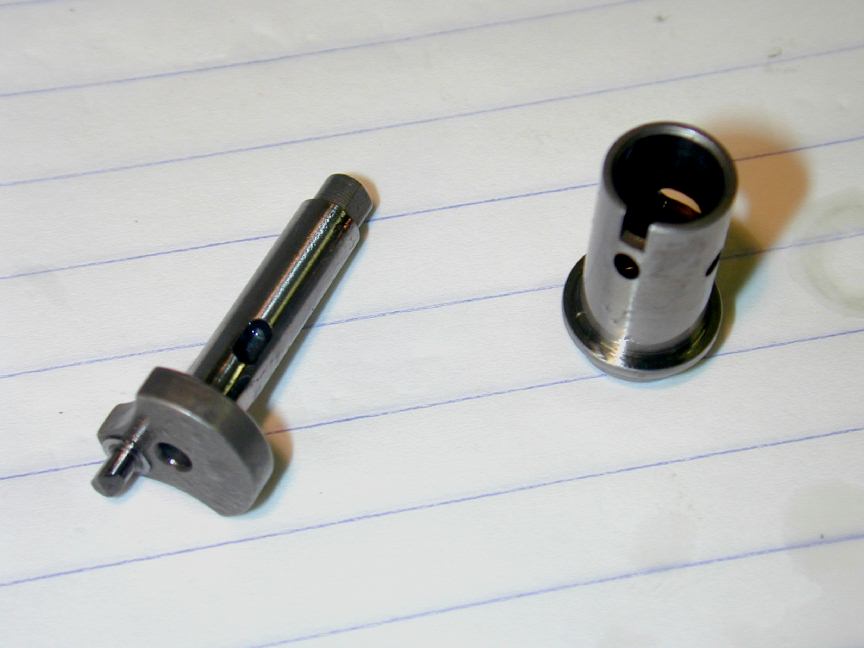 Here is the liner which is a drop in fit in the case. The slot in the liner registers with a 1-72 cap-head screw in the side of the crankcase to correctly align the ports and prevent the liner from rotating. Passages cast into the case at front and aft form the main transfer passages. The anti-rotation screw would block the boost passage, except there isn't one in the conventional sense. Instead, a little channel cast into the bulge above the screw feeds the boost port with mixture fed from a hole in the piston as mentioned before. This also assures that the piston can only be assembled correctly facing one way. The inexperienced often neglect to note which way a piston faced when disassembling an engine and have a 50% chance of reassembling it with the piston facing in a direction that essentially requires the engine be run-in all over again—or more likely, run-out! Look at the finish on he edges of the crank-web, the ground pad at the crank-pin base that prevents the rod rubbing on the web, the oval induction port, and the precisely angled Schnurle ports in the liner. It's like each engine was being made for a model engineering exhibition. The shaft uses a 4-40 screw to mount the prop. The prop driver is keyed by two little flats ground onto the shaft, just visible in this photo.
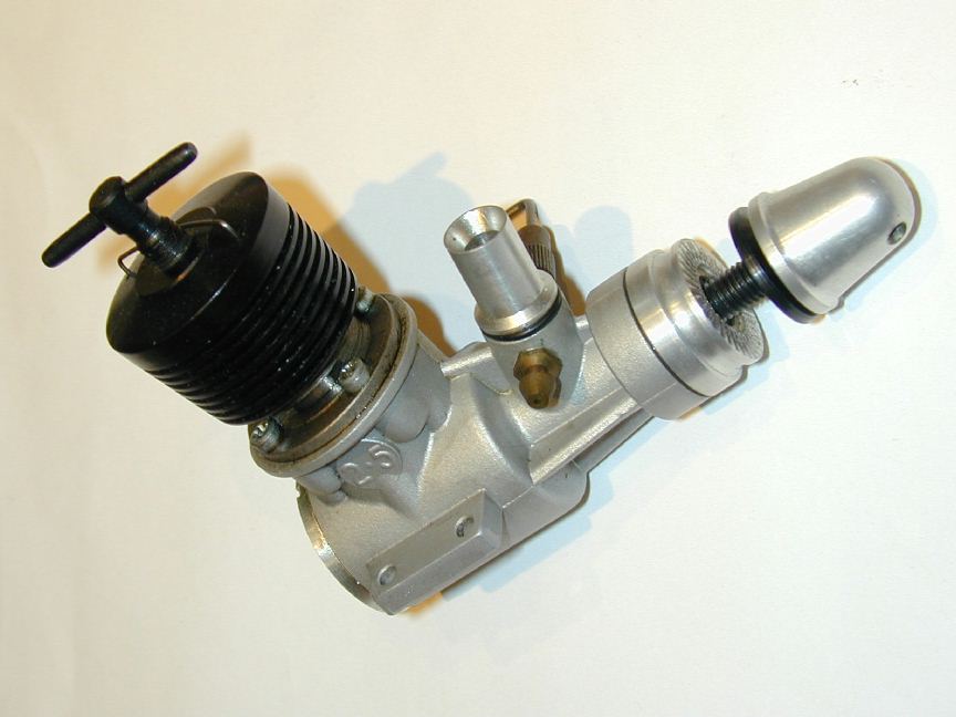
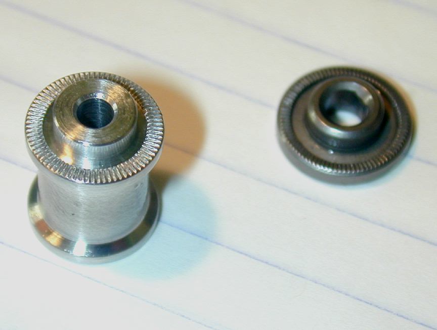 The propdriver is perfectly plunge knurled and fully hardened. This hardening and a slight protrusion on the main bronze bush ensure that should anyone use (ugghhh) an electric starter, the hard driver bears against the bronze and no bad things will happen. The cotton reel (if you remember such things) in this shot is the aluminium prop extension available as an accessory for the engine. Making this an accessory is about the only criticism I can direct at Peter's high commitment to quality and completeness. Even if you never use it, this neat little aid to engine cowling would be the absolute cream on the cake for a complete engine package that is so far ahead of the competition. About the only other touch would be a polished, dove-tailed, wooden box for packing (like Paul Bugel did with his team race diesels
  )!
)!
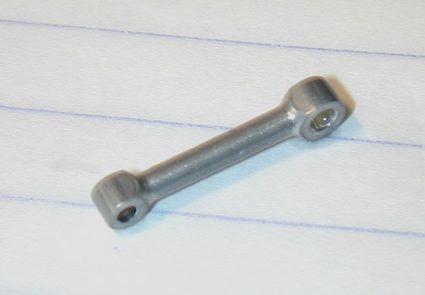 I especially liked the tiny conrod pictured here. It's aluminium, fully machined, and has the ends formed using the method I'd deduced while restoring a Taipan for a reader. This method, fully described on one of the Taipan Restoration pages, produces very clean profiles, simply and safely. But that only takes care of about 280 to 300 degrees of the end. The remainder must be machined integral with the rod shank in such a way that if merges neatly with the profile job. These rods are just about as perfect as you can get.
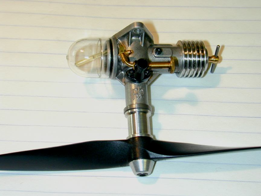
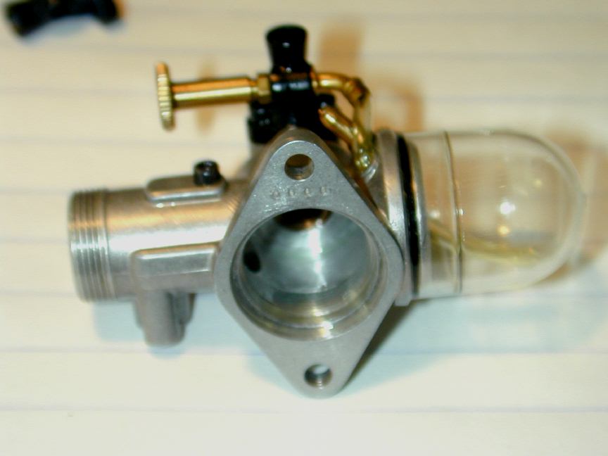
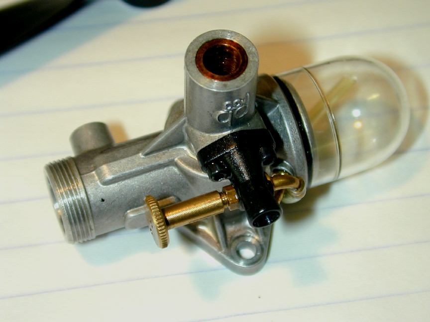 The inlet is an injection moulding that mounts to what we'd usually call the side of the engine with 1-72 cap-head screws. Knowing a thing or two about injection moulding, Peter was very particular in the plastic he wanted for the venturi and backplate. Unfortunately, it was only available from a single supplier in USA, and cost over 100 times what might have been used if this were not a no-compromise engine (oh wait, I forgot; this is NOT a no-compromise engine. yea, right...) but Peter did not weaken, he ordered the plastic he wanted for the job regardless of the absurd cost. Now, about the inlet position. While it can certainly be mounted with the cylinder poking up like an Arden Atom, Peter sees it mounted as a side-winder in a little control liner. This places the venturi upright, with the tank on the outside of the circle for centrifugal feed and would enable a very neat twin-cheek cowling to be fitted. Notice how the tank fill nipple would be above the filled position, so no leaks. There was a short lived British diesel called the Lion that used a similar arrangement of tank and cylinder in the late 40's. and Sparey designed a similar engine during World War II, although both disguised the tank as another cylinder head. Peter's tank is a crystal clear plastic injection moulding, snap fitted and sealed with an O ring. The little embossed ring on the tank allows it to be cut down for shorter engine runs in free flight models (each engine comes with two tanks, so this is not a drastic measure).
 Here's the same engine from the rear. Notice the serial number: four digits to accommodate the numbers envisaged. This one is 0000 - the production prototype (there were also pre-production prototypes). Engine 0001 is naturally going to Gordon, with other low numbers to people who have helped along the way. The plastic backplate screws into the recessed rear, registering on the light step in the case opening. The boost channel bump that also carries the liner locating screw is visible in this sorry excuse for a photograph. The screw is fully supported by the full depth of the bump; just above that is the short blind channel that connects the piston transfer port to the angled Schnurle boost port.
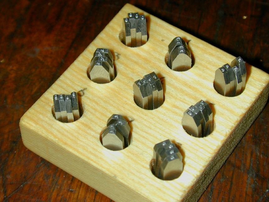 While on the subject of numbering, here are the number punches used to stamp the cases. They look spectacular, but began life as four sets of common, garden-variety MSC 1/32" number punches. First, Peter ground the sides very precisely in relation to the location of the number so four can be stacked to give the correct number spacing and the four-digit number stamped at once (explaining why there are four sets). Next, Peter painstakingly measured the baseline height of each numeral and ground the top and bottom of the punch so that all were exactly the same height, and all numbers shared a common, precise baseline. He says that as expected, no two were alike—all had to be individually measured and ground. He rates the surface grinder and magnetic chuck as one of the most essential pieces of workshop equipment. There's a matching wooden top for the stand. This prevents rust and all the production tooling (fully hardened tool steel) is kept in an old wooden wardrobe (ex Post Master General, if I recall correctly) for just this purpose.
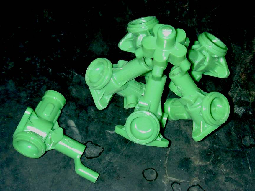
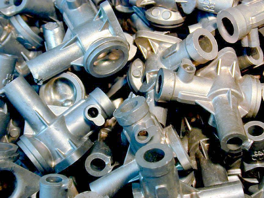 Here's a bucket of cases, heat-treated and ready for machining. The heat-treatment process is principally to improve the machinability of the alloy, the case being intrinsically rigid enough as cast. The main bearing is bushed with bronze that is pressed in as a light interference fit. The bushing is generous and while it is flush with the inside of the case cavity, a thrust face on the front of the crankshaft web of the same diameter as the bushing ensures that no contact with the aluminium case takes place. Peter was unable to obtain the grade of bearing bronze he wanted locally, so it was imported from England. I bet the freight was almost as much as the bronze—see why I keep saying "no compromises"?
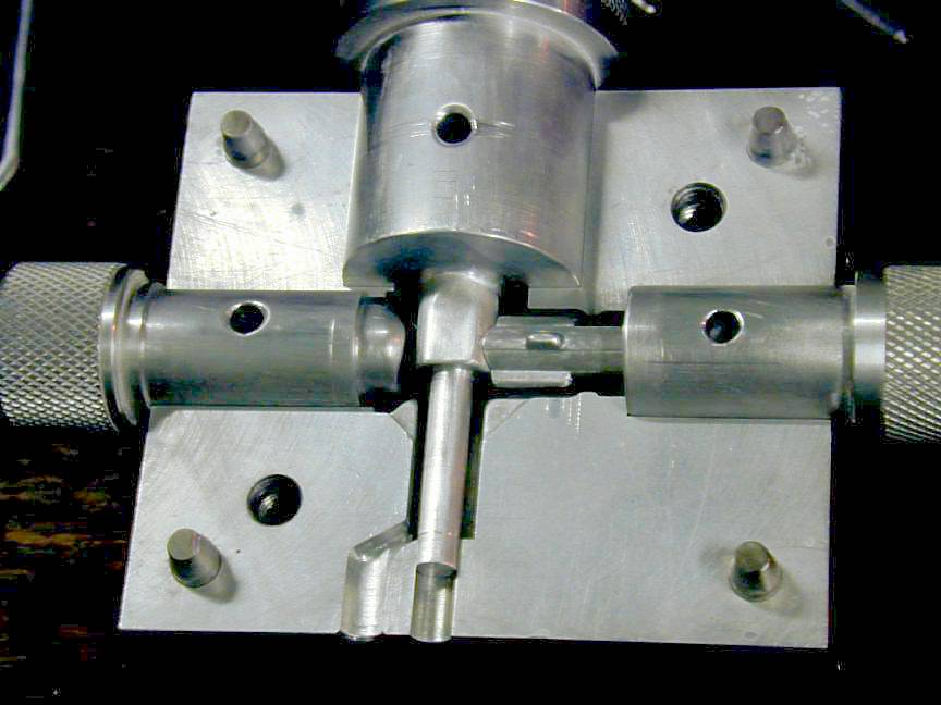
 This is the die for the crankcase investment wax. I barely know what we're looking at here—but I'll try to explain. In the middle are the two halves of the die that separate around the case vertical fore-aft center plane. As all parts of the case around this plane are simple curves, these halves will separate from the wax pattern. Note that the halves are keyed together with four dowel pins in the corners. Just inside two of these are two holes which take the clamping screws visible in the upper left corner of the shot. The large, stepped, circular plug at the top enters from the rear of the case. The steps form the inner case cavity and the main journal bore. Beside it is the plug that enters from the bottom and will form the inner surface of the fuel tank cradle. To the immediate right of the die is the plug that forms the cylinder bore. Note that it has three protrubances that will form the Schnurle ports in the inner case walls. Obviously, these would prevent the plug from being removed were it not for the fact that each bump is a separate sliding piece of metal that keys into the plug. This allows the circular part to be slid out leaving the lumps behind. Each can then be moved sideways into the space vacated by the plug, leaving the perfectly finished transfer port indent in the wax. One of these is sitting between the die and the plug. The bottom of the circular plug portion is concave to neatly wrap around the rear entry plug. To the right of that is... I dunno; beats the 'el outa me lieutenant. I've run out of die holes to put plugs in. Note that each plug has a hole in it, and so does the die. The "L" shaped thingies lock the plugs in place and assure their correct positioning. When Peter pulled the die apart, each of these slid freely from its hole, but with a distinct "pop" showing how close the fit.
 This piece of abstract art is a plate of stainless steel, photo-etched to form the little exhaust flapper. Diesels don't really throttle all that well, partly due to the interaction between engine speed, combustion heat, and compression setting. Peter though the engine would make a good "school-yard R/C" engine if it could be controlled a bit. He reports partial success: closing the flapper drops the RPM by about 20%. It also drops the noise to near nothing (you can't get nothing because the prop itself makes quite a racket, as electric fans know). I thought these were punched, but Peter said there'd be no way to do this in stainless without leaving a bur, so he prevailed on his contacts and had them etched out. He enough of these plates to finish his 3000 engine run, if he chooses to.
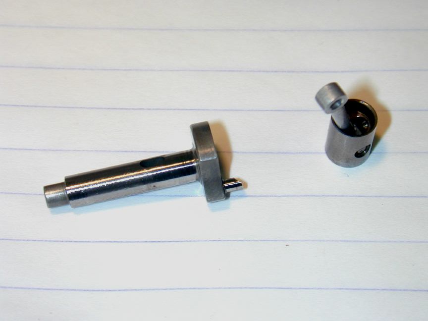
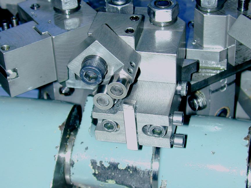 The amount of tooling and jigs and fixtures that have been built to construct this engine is astounding. I especially liked this little roller-box fitted to the big turret lathe. The hardened steel rollers work as a low-friction travelling-steady as the tool is fed up the work. Peter didn't say what this one is setup for, but it looks like the crankshaft to me (imagine not having to fuss with a center support—impossible anyway in a turret lathe). I've just got to make one of these oneday.
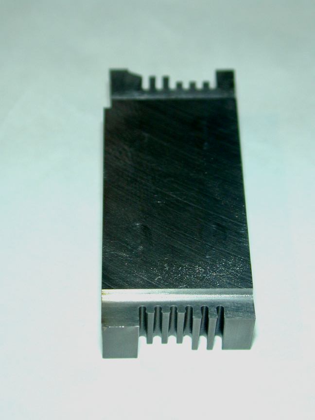 This, obviously, is the tool used to profile the cooling heads. Naturally it's hardened tool steel. Now look closely. Note that each cutting blade has the correct front and side rake, and the inside and outside corners are perfectly rounded to form both fin and gap profiles. I was trying to imagine how I'd grind this on the Quorn until Peter put me out of my misery saying it was wire-cut with an EDM. The other end of the block has a like shape—makes sense; after the machine is programmed to cut one, why not bash out another on the other end as a spare and to increase the time between sharpenings. Tools like this (and a honkin' big lathe) reduce to seconds what would take me tens of minutes, a fin at a time on the poor little Myford.
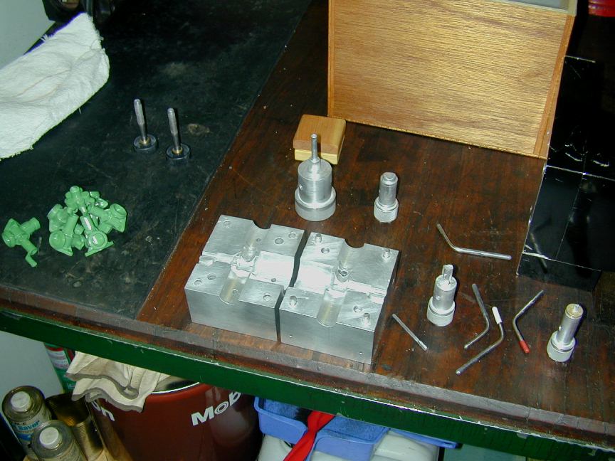
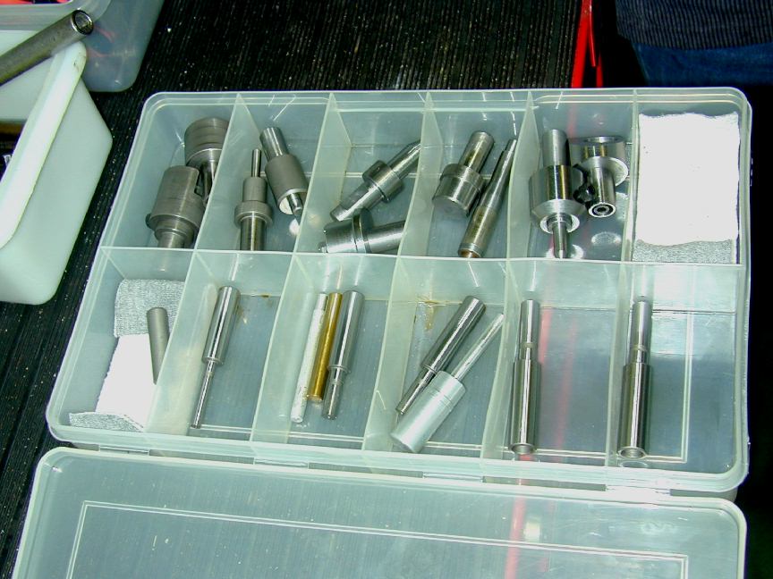 More tooling. This box contains various mandrels and, in the upper left compartment, the very cunning tool mentioned earlier for assembling (permanently!) the piston, rod, and wrist pin. One half of the tool holds and locates the piston via the counter-bored recess on one side of the wrist-pin hole. With the rod positioned and the pin resting in place, the other half presses the pin semi-permanently into the rod. The two halves of the tool come together just as the rod reaches the mid-point of the wrist-pin. No fuss, no mess, no guessing. Incidentally, Peter fully expects owners to dismantle their PB .33, though dismantling the pressed in wrist pin is not something he expects anyone will have a real need to do. As you can see, re-assembly to the same precision that Peter achieves effortlessly would not be a simple matter.
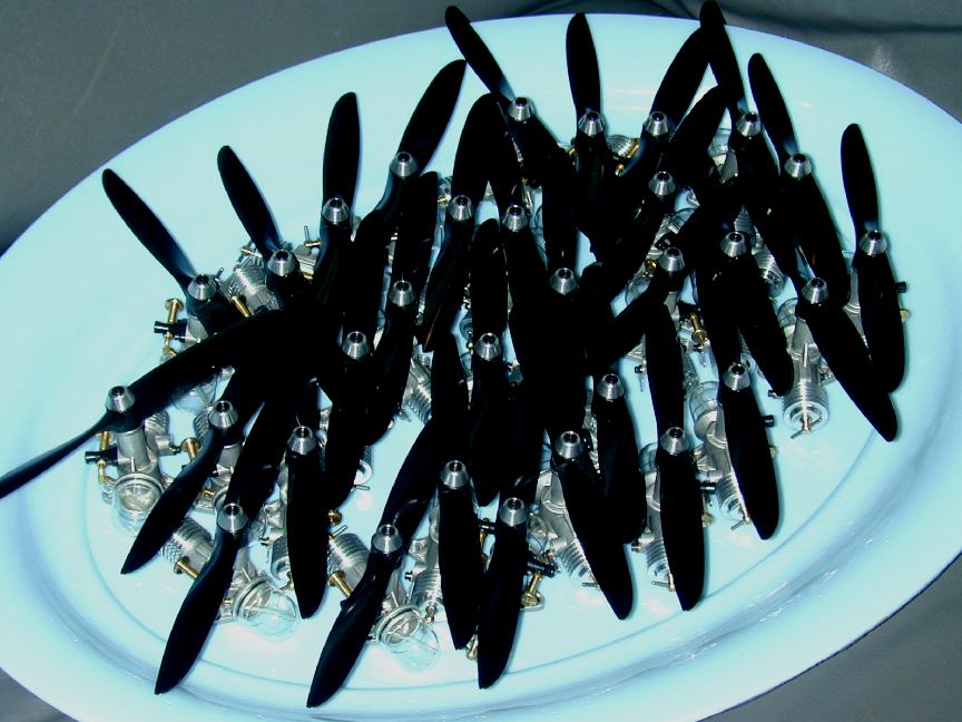
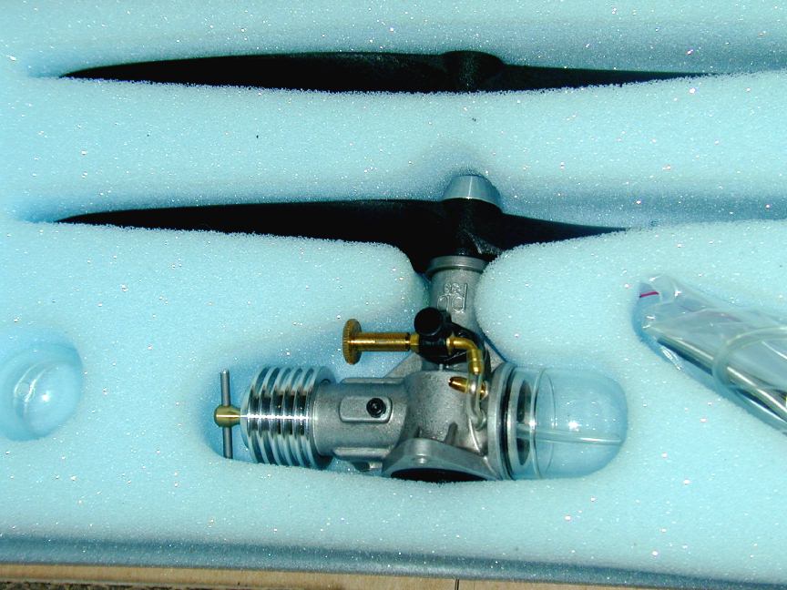 As I write this in late May, 2004, the PB .33 is ready to ship. Here we see a platter of engines ready for test running, and the packaging. Note that each engine comes with two propellers (a 6x3 and a 6x4), a spare fuel tank, O rings, a set of Allen keys, and an extra length of fuel tube. All are packed in a generous foam insert. Operating instructions are on a double sided A4 sheet. The price is admittedly high: A$500, plus shipping. There will be no agents, no bulk deals, and no discounts. Peter knows that many will call this "overpriced", but he has considered what it takes and has taken to build them and priced to make the engine give him a modest return on this time. If the market votes a resounding "no way" to the price, he is quite prepared to make no more of them. If this seems extreme, there is a precedent: he confirmed the story about an entire production run of Taipans being used as fill under the concrete floor of the Adelaide Taipan factory—he should know, as he helped pour the concrete over them! So are they worth it? Well that's up to individuals to decide. The engine is not a beginners' engine—no small diesel is, really. These are engines for the connoisseur and are intended to be flown, not sit in a glass case—though I don't doubt that many will do just that. I have no connection with Peter, or this venture—I'm just another customer who feels that the engine will give me my $500 worth of joy. The rest of the world will make up their own minds and time will tell...
![]()