Pachasa Air Engine (1928)
Click on photos to view them full size.
 |
 |
 |
| Name | Modelmaker Air Engine | Designer | Edward T Pachasa |
| Type | Air expansion | Displacement | 0.196 cuin (3.22cc) |
| Bore | 0.500" | Stroke | 0.500" |
| Production run | Plans Only | Country of Origin | USA |
| Photo by | Les Stone, Ron C |
Year of publication | 1928 |
Background

To spin the propeller of our model aircraft, we need an energy source and something to convert that to rotary motion. Today, electric motors and exotic batteries seem to be taking over. Prior to that, it was our beloved, smelly, noisy, miniature internal combustion engines (with a variety of fuel types). Before that, the energy captured in a wound up skein of rubber and a "thrust bearing" did the job. And prior to that, the energy came from expanding gas, driving a motor based on steam engine technology (we'll ignore the relatively few actual steam powered models, apart from acknowledging them and their creators like Langley and HH Groves). This is a logical progression. At the start of the 20th century, internal combustion development was still in its infancy and rubber was not all that common, while steam power was ubiquitous. Miniature steam generation plants are heavy and difficult to make, so early model aeroplane experimenters such as Australian, Laurence Hargraves (whose face and models once graced the back of our $20 note), found that compressed air could drive a lightweight motor based on steam engine principles, providing ample power and run duration for his well documented experiments.
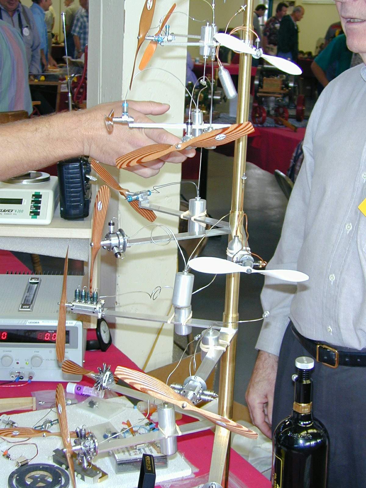 Engines of this type are termed Expansion Engines. The method of creating a gas under pressure is not always a bike-pump either. Carbon di-oxide (CO2) engines appeared commercially as early as 1909[1], although the pioneer IC engine designer Bill Brown IV was granted a US patent for such an engine in 1946 and is frequently cited as father of the CO2 engine. Commercial CO2 engines have come and gone over the years from numerous manufacturers. Best known of current manufacture are the exquisite single and multi-cylinder engines designed by Stephen Gasparin, pictured here from a display stand at the 1999 PRIME exhibition. Such complex radial and rotary CO2 engines are by no means new; several different commercial products of French manufacture having appeared as early as 1911[2]. However the production of CO2 is complex and relatively expensive. In contrast, air can be easily compressed, and is free.
 Commercial expansion engines powered by compressed air appeared only slightly later than C02 engines. Again, the lead seems to have been in Europe, with the French and Germans[3]. In England, Gamages Limited were marketing a number of complete air plants and even RTF expansion powered models in 1914. Plans for home construction (on topic at last!
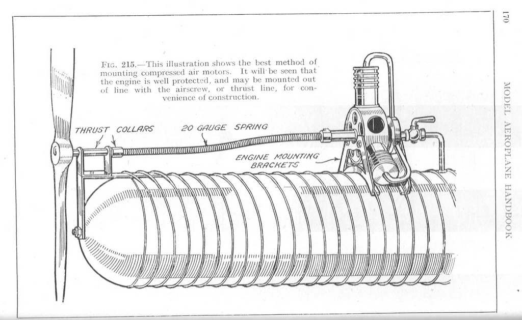
  ) appeared about the same time and continued to appear well after the introduction of practical, miniature internal combustion engines. The engine pictured here, designed by FJ Camm, appeared in 1949. It used a floating conical rotary valve forced onto its seat by air pressure from the tank. The latter being made from very thin (0.003") copper foil wound with a spiral of 26 SWG steel wire (0.018"). The wire is soldered to the container at the ends only and imparted strength to the cylinder body. The domed end caps have a 3/32" tie-rod which passes down the length of the container providing some longitudinal strength[4]. Interestingly, this illustration is reproduced in Bertram Pond's book under the caption What Is Wrong With This Design. He then lists 15 salient observations, the last being "15.Conclusion: such inept designs have not benefited model aviation."[5] Although the majority of his criticisms are quite valid, this seems a bit harsh. Trans-Atlantic bias, perhaps?
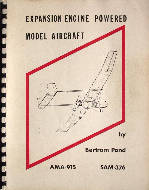 For a number of years, the same Bert Pond wrote a regular column, Air Power, () on expansion powered engines for The Engine Collectors' Journal. This material and much more appears in his self-published book, Expansion Engine Powered Model Aircraft. Sadly, Bert Pond is no longer with us and his book, the most comprehensive of its type ever written, is no longer available. There were two versions with identical content, a loose spiral bound version and the same pages, hard covered with sewn pages. If you are interested in this topic and ever have a chance to get a copy, don't blink (or quibble over the price), just grab it. Included are historical background, drawings for 14 engines of different configurations (including two "walking beam" designs), numerous airframes, and a modern way of making practical air tanks from aluminum drink cans and plastic soft drink containers.
In the USA, catalogues from the late 20's list air engines, complete with tank, for between $14 and $20 (a significant sum in 1929). Air engine kits were available from $3 upwards[6]. In 1928, Ed Pachasa, who founded and headed the Cleveland Model & Supply Company, designed a two cylinder air engine that was constructed by his brother William (Ed changed his name to Packard in 1955 while his brothers retained the unpronounceable family name). The result, as noted by Pond, was submitted for publication, appearing serialized in the March, April, and May issues of The Model Maker[7].
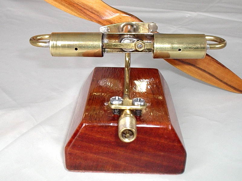
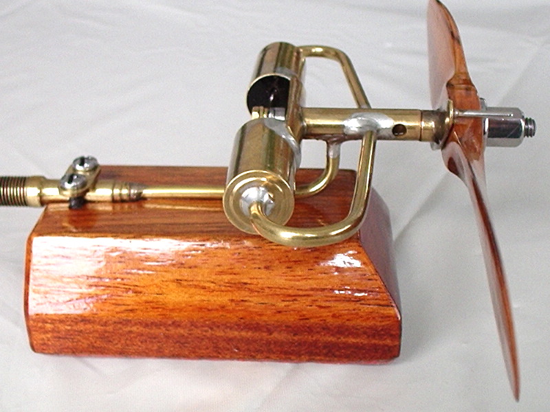
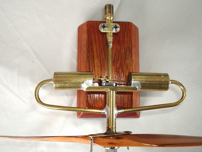
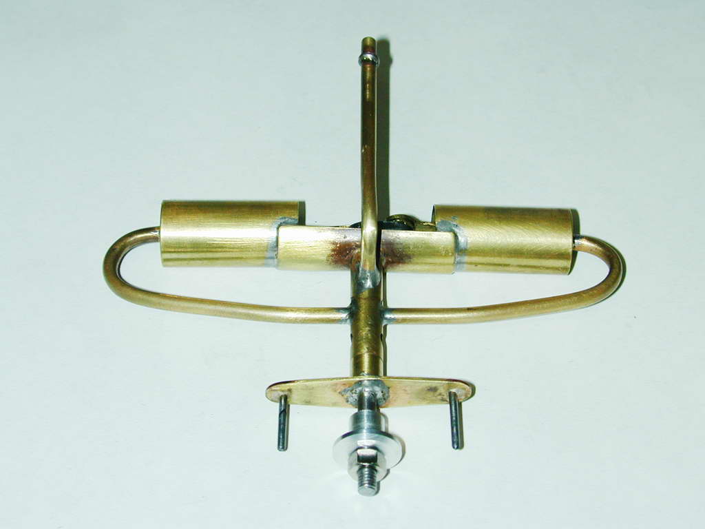
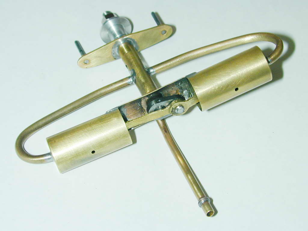
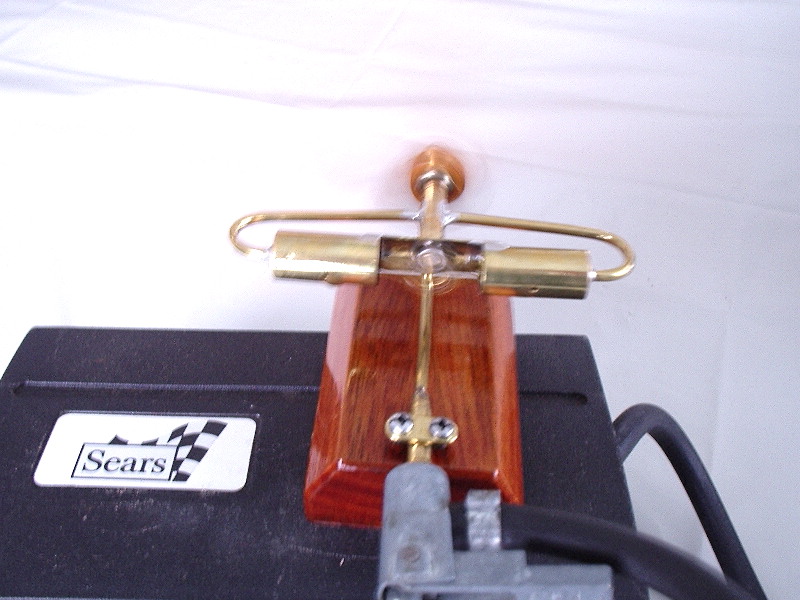 The Pachasa/Packard design has resurfaced a number of times since. In the 60's, a kit of parts was available prompting Roger J Schroeder to redraw them for publication as a construction article for the Engine Collectors' Journal of March-April, 1969. For a period of time, Roger also sold a kit of raw materials to make the engine. The example at the head of this page and shown here running from a 12v tire pump, was made by Les Stone from one of Roger's kits.
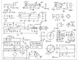 Material kits are no longer available, but practically everything you need can be bought from the K&S metals rack at your local model store. Roger has kindly placed his drawings and instructions in the public domain. Click on the picture, or follow this link to Roger's Pachasa Construction Article. Take a moment to look at them now. Feel free to print a copy and pass it around.
Operation
Now let's look at the timing. We'll assume the valve is machined precisely to the drawings and that the ID of the inlet and transfer tubes is 3/32", while the exhaust holes are 1/8" in diameter. The engine is timed so that the inlet opens when the piston is 1/32" from TDC, or 25° ATDC. The air inlet remains open for 65° of rotation. 102° after the inlet closes, the exhaust opens for a period of 180°. Then, 13° degrees of rotation later, the cycle repeats.
If you add all this up and take away the number you first thought of, you'll find it is all quite neat. Air enters the cylinder 25° ATDC pushing the piston downwards. The admitted air is cut off with the piston 90° ATDC, but in the best live steam tradition, continues to do work as it expands in the cylinder, pushing on the piston (with rapidly reducing force) as it does so, until the piston has passed BDC and is 12° into its upwards stroke when the exhaust valve opens.
But did you notice the little 1/16" hole in the cylinder? This is uncovered by the piston on its down-stroke when it is 54° from BDC. So the actual expansion period is only 36° with the cylinder volume open to atmospheric pressure as the piston passes through BDC, rises, and again occludes the hole in the cylinder wall.
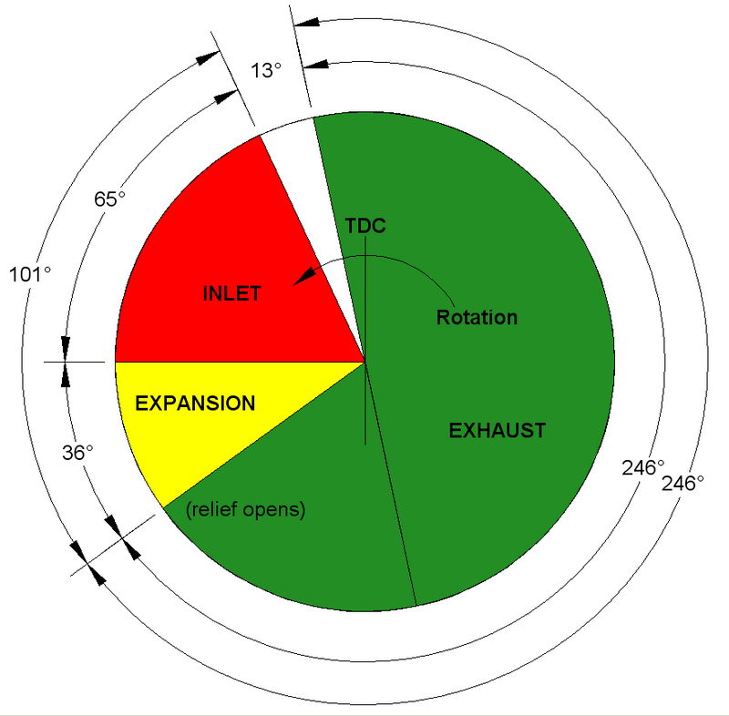 But by this time, the exhaust valve has opened and instead of trying to re-compress the air in the cylinder, it is pushed out through the transfer tube for the next 180° of rotation until the piston has passed TDC by 12°. We then have a period of 13° during which the piston is trying to suck from no place, but as piston velocity is sinusoidal, movement is small around top and bottom dead center, so this is not a great problem and the small delay ensures we are not in danger of venting valuable energy through the exhaust. We've only considered one cylinder. Events in the other will be identical, but occur 180° out of phase, giving a very balanced power stroke, even if the reciprocating mass is not all that well balanced.
Building
Les was unable to show the internals of his engine as final assembly is a somewhat permanent process. So I decided to do a quick build and take some photos, making this a combination of review and construction article. Materials wise, get some K&S tube with a 1/2" ID for the cylinders and a strip of 1" wide K&S 1/32" brass for the other bits. You may want to cheat and get a length of 33/32" ID brass tube to use for part (C). This is thinner than specified, but sure simplifies things. The shaft can be made from a length of 3/16" diameter drill rod, polished to a free but close fit in the hole reamed in the bushing part (F) which is made from 1/4" brass rod (K&S again, although the price for brass rod is a bit outrageous). You can't really use tubing for the bushing as it will be too thin to give adequate support for the inlet and transfer tubes. These are made from an annealed length of 1/8" OD K&S brass tube.
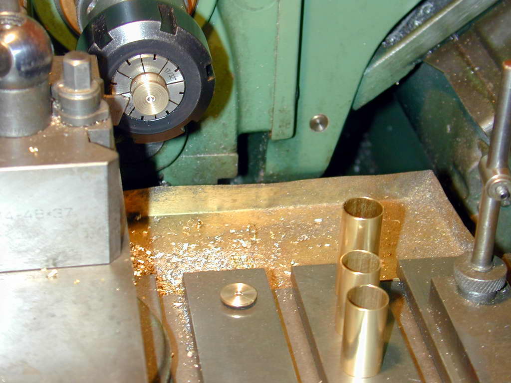 For the cylinder heads, I cheated and parted them off from 1/2" round brass stock. While this produced more swarf than component, it was easier than mounting pieces of 1/32" shim for turning. The rod was drilled before parting off for the central transfer tube. If you are lucky enough to have a set of lathe collets that will take the tubes, this is the way to go for cutting and truing the thin walled brass tube. Don't be tempted to grip it in a 3-jaw chuck as the jaws will distort the thin wall tube making it unusable.
 As recommended in Roger's instructions, the use of a high melting temperature silver solder for the heads and joining of parts (C), (F), and (P) will reduce frustration of the "oh dear, it all fell apart" kind. Silver solder melts about 200° higher than 60/40 lead/tin electrical solder, but I went all the way and used silver braze. As well as giving almost 1000° of latitude, this polishes up like brass and makes the joint at the cylinder head invisible.
 If your scrap bin does not have any 3/32" steel for the crank web (D), this too can be parted off from a suitable length of steel barstock. Make the hole in the web a tight but movable fit on the shaft. This will help keep things in place when you set the timing. To make assembly as easy as possible, the 3/32" drill rod crankpin should be only long enough for the conrods and a retainer as the rods have to be lifted and jiggled onto the pin.
 Material for the pistons will be problematic. The 1928 instructions call for phenolic rod (a linen material, impregnated with resin and cured under pressure). This is light and machines well, if you can get it. An alternate material is PTFE rod. This is heavier, but will have lower friction and is fairly readily available from bearing supply shops. It machines well with a razor sharp tool. In any case, make life simpler by leaving both pistons on the stub until the holes and slots for the conrods have been cut.
While talking about the piston, it's worth noting the in his write-up of the Pachasa design, Bert Pond says that the piston is too short to provide a good seal and long working life. He recommends that as a rule of thumb, the piston height should be at least equal to the bore (the height shown on the plan is 1/2 the bore)[7]. Naturally, the rod length will need to be reduced to compensate. I have mixed feeling about this. Longer pistons mean more friction. It would also prevent them from being removed (they'd hit the bearing before clearing the cylinder skirt). You may not need to ever remove them, but it's nice to know you can.
 Pond also suggests making the conrods the same length between centers and jiggling them to run true and free. Whichever way you decide to go, filing them to shape is a tedious process. The best assist for this task, this side of a CNC mill, is to make some "filing buttons". These are pieces of drill rod of the appropriate diameter, drilled to take stub shafts appropriate to the ends, then fully hardened; ie, don't temper, leave them "glass hard". Clamped either side of a rod end, you can file away with gay abandon; the file won't touch them when it hits them, and strangely, they don't seem to damage the file either. The result is a neat-ish end with straight sides. This shot gives a "before and after" comparison.
 The tubework is not difficult, but you will need to anneal the tube, and make a bending jig with an inside radius of about 1/4", or slightly less. A simple square bottomed slot 1/8" wide and deep in some suitable piece of scrap is all that's required. The tube should be a firm fit in the slot to prevent distortion due to flattening. Mine, seen here in the foreground, has made from a piece of nylon rod. In the background is a Harry Higley bender which uses a pin to hold the free end of the tube while it's being bent. This is a BAD idea. The point contact of the pin will place a most unsightly indent in the annealed tube. Instead, with the jig in the bench vice, place the tube in the groove away from you and hold it in place with a steel ruler. Push the tube into the groove applying pressure where the free end emerges from the slot; it really is easy. And in case you don't know, brass is annealed by heating to red heat. You can air-cool, or quench in water; makes no difference. Finally, remember to polish the tube before bending it—much easier than after!
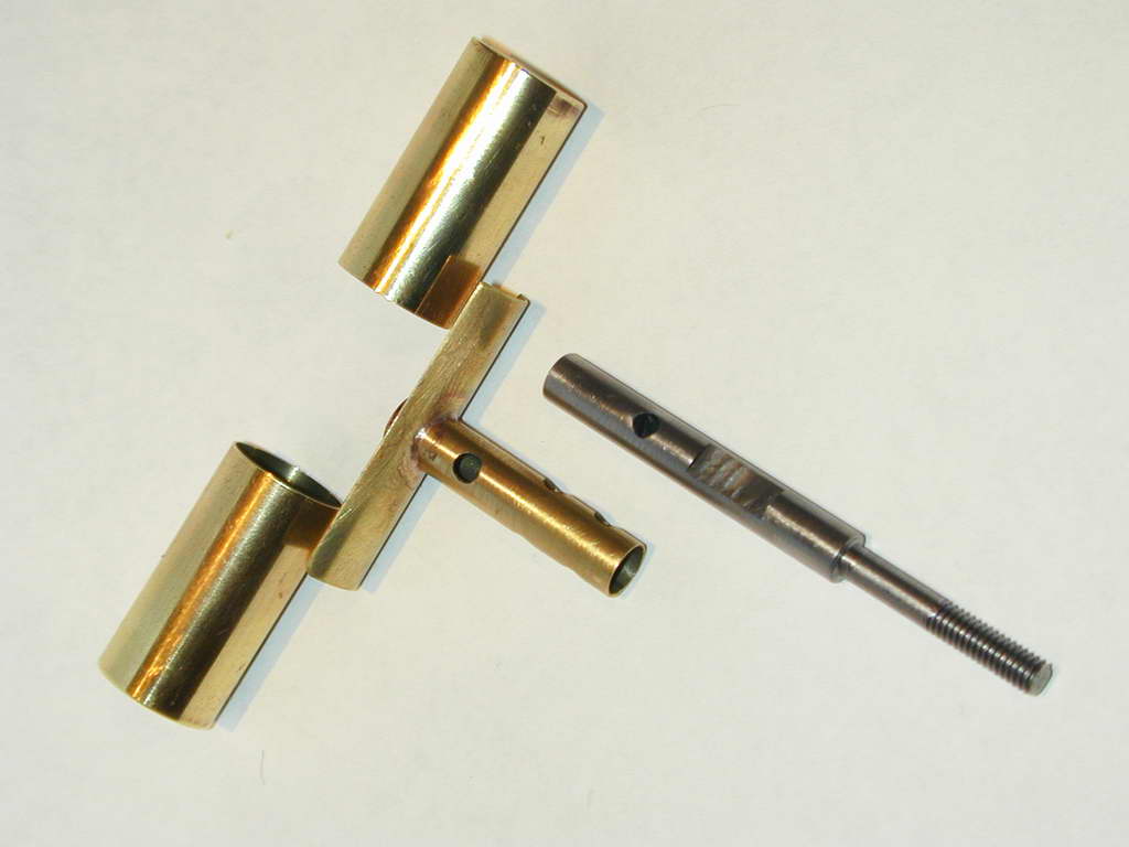
 Here's the parts ready for final assembly. The cylinders were tinned where they contact the joiner (C), as was the inside of the joiner. While the solder is still molten, wipe it off with a dry cloth. This gives a regular surface for joining, without excess solder. With the crank at TDC for the cylinder being soldered, fit the rod to the crankpin, push the piston all the way to the top, then raise the cylinder by 10-20 thou to give a little clearance at TDC. Sweat the cylinder in place and repeat for the other. The transfer tubes can then be soldered in place. Adjust their length so they don't intrude into either the head or the bearing. You can run the reamer through the bearing again afterwards to tidy up, but there's nothing you can do except start again if the tube protrudes into the head and strikes the piston.
Final Assembly and Running
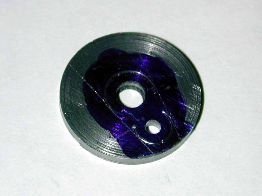
 To time the engine, position a piston about 25° after TDC in the direction of normal rotation and hold it there via the crank web. Rotate the shaft in the normal direction of rotation while blowing into the air inlet tube. As soon as you feel air starting to flow, stop and mark the position by scratching across web and shaft end. I cross-drilled web and shaft for a 1/16" roll-pin. You could solder it, but if you do, silver brazing is recommended. Insert the shaft in the bushing, then drop the spacer (G) onto the shaft, followed by the prop driver plate (it's a good idea to silver solder the drive pins in first). Solder the plate to the shaft first, then invert and solder the spacer to the plate. This will give the minimal end play required for air-sealing.
 Bend a little circle of copper hook-up wire around a 3/32" former, then cut through on one side to form a little washer. With the rods in place, put a piece of brown paper with a 3/32" hole in it over the crank pin, followed by the "washer", then solder in place with minimal solder. The brown paper will prevent the solder getting to the top conrod and gluing everything shut. A similar washer comprising two turns of copper wire was soldered in place to form a ferrule on the end of the air supply pipe. This prevents the flexible air tube being spat off under pressure.
Drop some light oil into the cylinders through the air cheater holes. Add more oil to the shaft through the exhaust ports. The type of oil used for air-tools seems like a good choice. Hook up the air supply to something capable of maintaining at least 20 psi. Be prepared for a surprise—the engine may self-start if one piston is just after TDC. Otherwise, a simple flip will get it away. You can even hold it in your hand while it runs; unless you have excess friction, air engine cylinders tend to get cold rather than hot (the cooling fins on the heads of the Camm engine was one of Bert Pond's accurate criticisms).
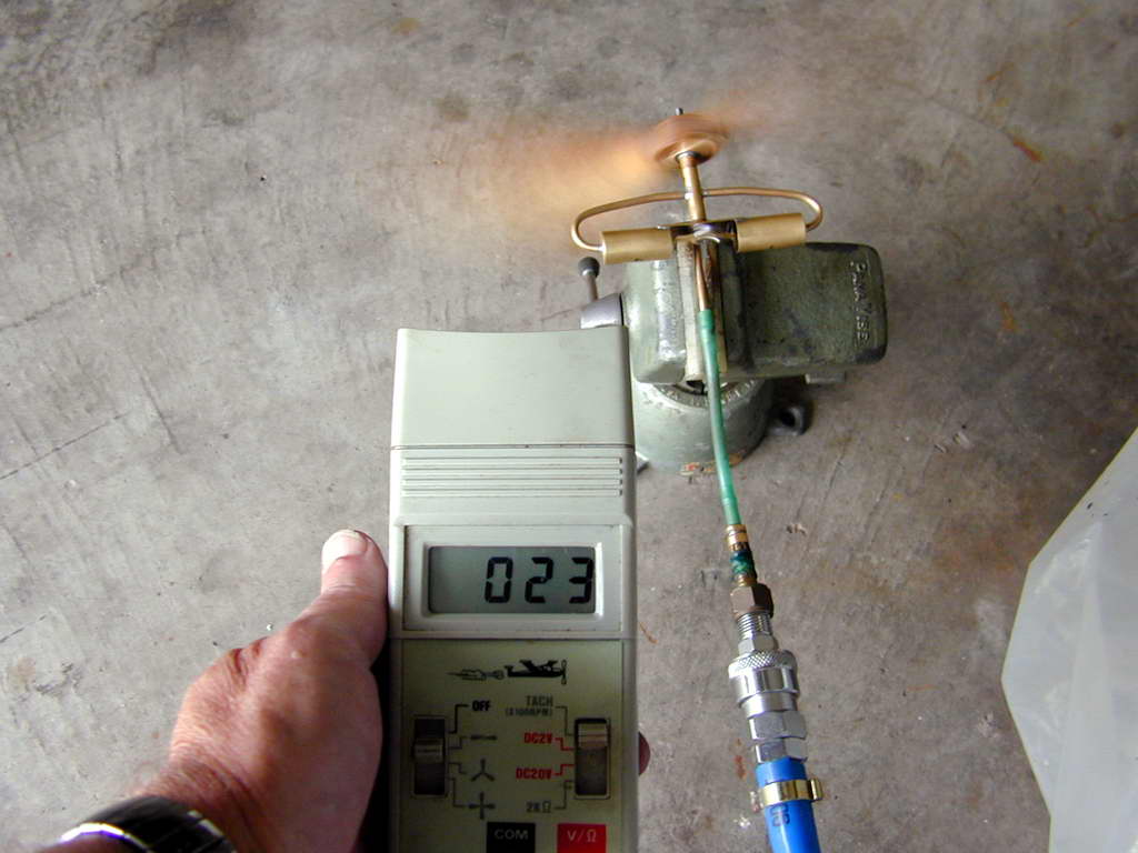 Here's the brand new Pachasa spinning an 11x7 Zinger at 2,300 rpm on 30 psi. At a constant 20 psi, it spun the 11x7 at 1,600 rpm, a 7x6 Topflight wood at 1,700 rpm, and a whopping 14x4 Topflight wood at 1,500 rpm! This suggests to me that most of the power is going into combating friction rather than the load imposed by the prop. The engine is not overly tight, but I decided to see if it'd loosen and improve with more running. So with the 7x6 in place, it was cranked up the maximum rpm of 3,000 rpm, at which point, it would go no faster regardless of the pressure. While I was contemplating this and enjoying the sight, it spat off the air supply. I found the engine was seized almost solid.
Lesson learnt: air contains no lubricant. Expansion engines need lubrication before every run, and runs should not be extended as when the oil is gone, it's gone and things go downhill quickly from there. My problem was shaft to bushing. I've freed it and learnt a valuable lesson about fuels that don't contain a lubricant.
Conclusion
Building the Pachasa Air Engine was not difficult and the results are most pleasing. It would most definitely fly a large, light model, given a suitable air reservoir like a 2 litre plastic bottle. And yes, you can buy RTF expansion engine models in the toy store, but making your own to a vintage and historic design is much more satisfying. Thanks go to Roger Schroeder for keeping this design alive.
References
| [1] | Suzor, G: Petits Moteurs pour Mod�les R�duits, Maeght Editeur SA, France, 1938, p19. |
| [2] | ibid. p24. |
| [3] | ibid. p29. |
| [4] | Camm, FJ: Model Aeroplane Handbook, George Newness Ltd, London, 1949, ch16. |
| [5] | Pond, B: Expansion Powered Model Aircraft, Self-published, Longmeadow, USA (undated), p31. |
| [6] | Anderson, F: Golden Age of Model Airplanes, Anderson Publications, USA, 1997, p109. |
| [7] | op.cit. p36. |
Back to the Model Engine News Home Page