Thorning Monsunen
Created: Aug 2007
 |
 |
 |
 |
Click on images to view larger picture.
| Name | Thorning Bensen Monsunen | Designer | Jorgen Dommergaard (?) |
| Bore | 11.7 mm | Stroke | 19 mm |
| Type | Compression Ignition | Capacity | 2.4cc (0.147cuin) |
| Production run | (home construction) | Country of Origin | Denmark (Helsingør) |
| Photo by | Schroeder | Year of design | 1945 |
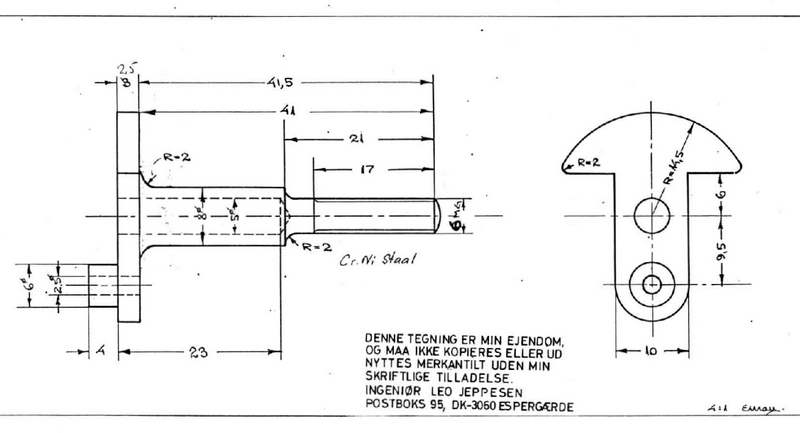
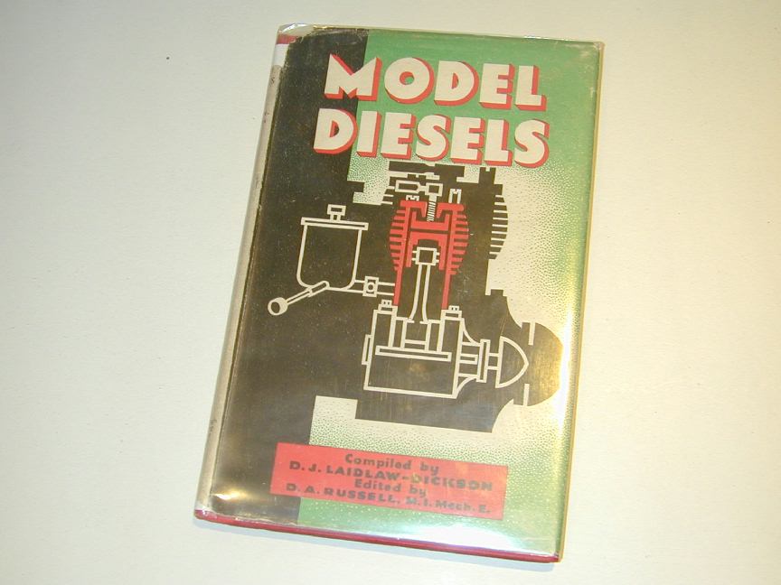
A set of what appeared to be quite professional drawings for this Danish diesel came into our hands years ago. It is a long stroke, side-port design featuring a rear exhaust, Schnurle-like transfer porting, and a look that manages to be both vintage and modern at the same time. A date on one of the photocopy of a photocopy sheets suggests it was designed in 1945. Laidlaw-Dickson's 1946 book, Model Diesels says that the Danish firm of Leo Jeppesen of Snekkersten, near Elsinore (sic), produced a 2.4cc diesel called the Monsun Standard. This engine had been designed by Jorgen Dommergaard, a well-known modeller in Denmark at that time. Although the book contains no photographs, the text notes that:
"The cooling fins on this model are few and small; in fact, the designer declares they are not necessary at all, but customers like them! He has recently backed that declaration by producing the Thorning Bensen 1A, which is a development of the Monsun, and this model has no ribs (sic) at all. Presumably he has talked customers round. Anyway, the Monsun Standard is a good-looking job with a reputation. The prototype was test run for more than one hundred hous without ill effects, on several occasions for eight hours non-stop." [1]
One hundred hours!? Diesel fuel must have been cheap back then. The stated capacity for the Monsun 1A (2.4cc) matches exactly "our" Monsun. And while the drawings we have show two cylinders, one with three fins, the other five, they do indeed have those useless fins the customers like so much. But lacking anything better, it is probably safe to credit the design to Jorgen Dommergaard.
All the Motor Boys liked the look of the engine and put it onto the list of must build someday engines, where it was promptly forgotten. But it kept resurfacing until finally some pictures of a modern reproduction (below) that pushed us over the edge into some form of action.
As a first step, it somehow got decided that a standard set of MBI CAD plans should be produced. The question quickly arose of whether the plans should be metric—per the originals—or Imperial, to suit most of out machine dials. Someone said "both" and my own particular problems began. First, metric CAD versions of the originals were made and "assembled". At this point I discovered that not only would an engine built exactly to the provided dimensions not turn over, it could not even be assembled! The timing had ludicrously wide inlet duration that would blow as much fuel out the inlet as it ingested, and the port layout almost guarenteed leakage between transfer and the outside world via the exhaust.
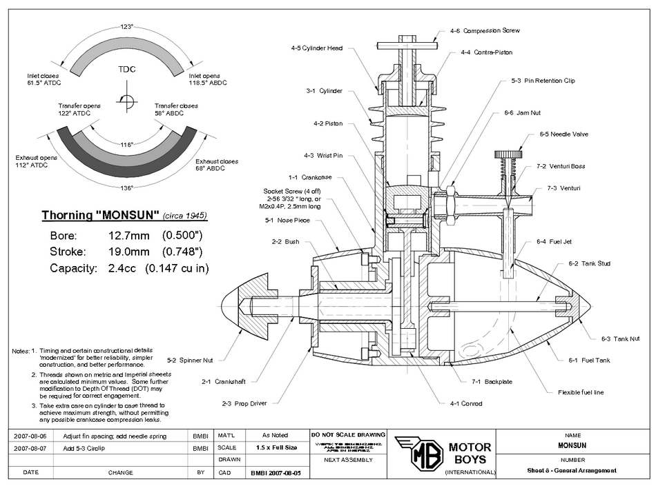 After a lot of finessing, the parts could be assembled with a timing adjusted to as close as sensible as it is possible to get when the inlet sits directly beneath the exhaust with a side-port configuration. All this was done using metric drawings (much easier to produce than Imperial). The parts were then copied to another set of Imperial sheets for final dimensioning of both. This set of gymnastics was required because TurboCAD does not do a good job of translating things like dimension lines and line "weights" between measurement systems—or if it does, I've never discovered the trick. The final result is 15 sheets of drawing: two each for the parts, plus a common General Arrangement.
Assembly will still be fun. It is not obvious, but the wrist pin does not fully emerge from the crankcase at TDC. The cylinder bore in the case does not allow an assembled piston and conrod to be slipped over the crankpin, so the only way to fit the pin is through the exhaust. If it can go in, it can come out—quite irritating if the engine happens to be running at the time. So a circlip arrangement has been drawn in to retain the wrist pin. The latter being threaded internally for a short length to facilitate removal. An alternate scheme proposed was to make an alloy wrist pin carrier with a screw-on piston shell. This would also lighten the rather heavy piston and some builders may opt for this arrangement instead.
Then there's the screw-in liner whose final position, with gasket, must be determined before the ports are cut. Another obscure but important point is the thread cut in the case for the liner. Cut this 0.1mm too deep into the case and all the primary compression will exit via the thread and the exhaust. All in all, attractive and relatively simple, but not an engine for the beginner.
 |
 |
 |
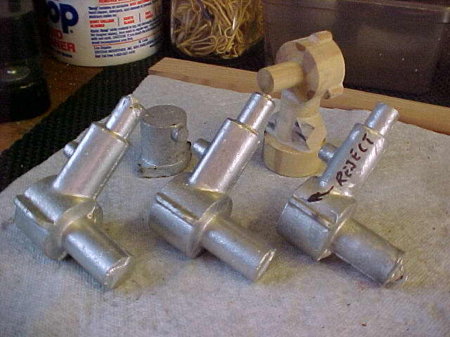 |
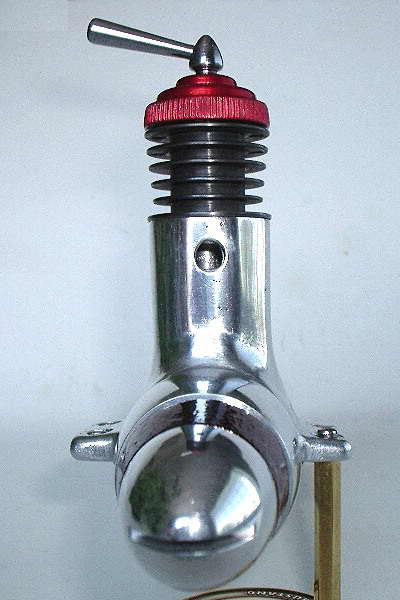
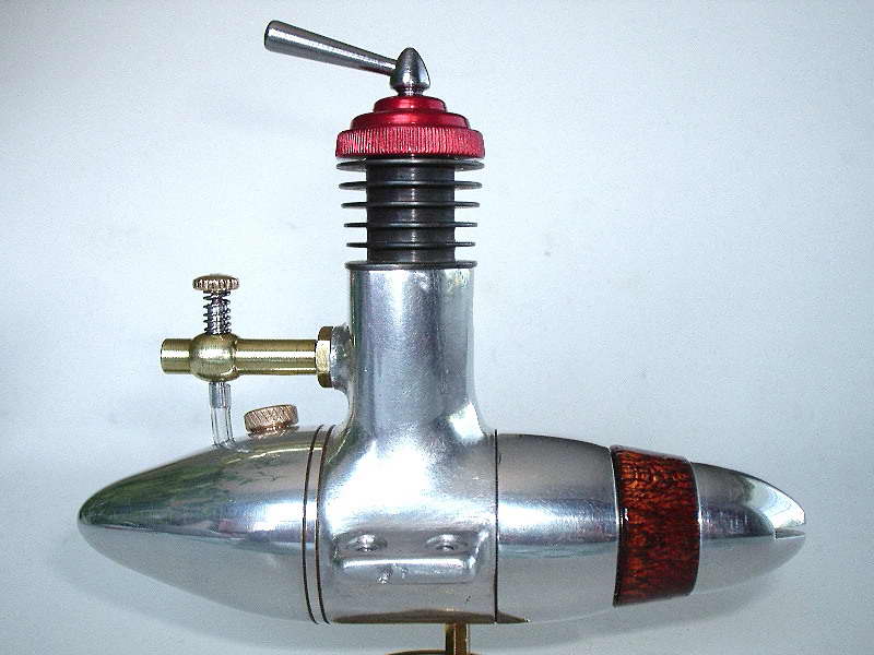
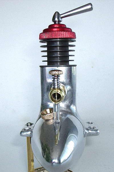
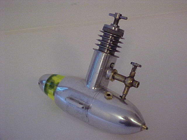
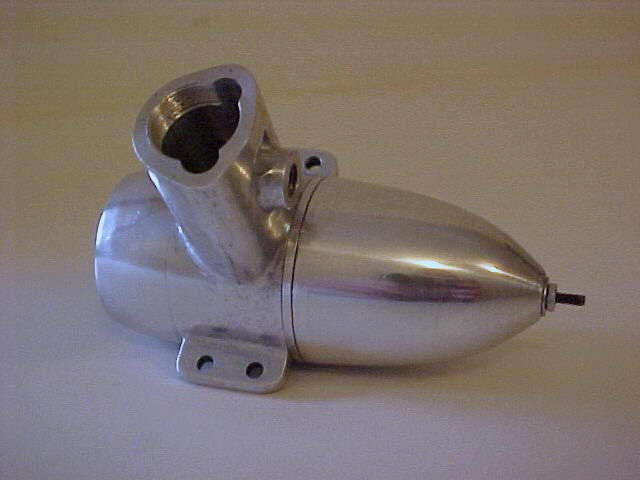
The photos here show an example built from the original plans. The shot with the cylinder removed reveals the location of the transfer passages that give the crankcase cylinder projection its characteristic Reuleaux cross-section. The liner transfer ports are cut to direct the charge away from the exhaust providing Schnurle porting without the "boost" port (which is not mandatory anyway to qualify under the original patent). The down side is the clustering of all openings in the one area of the liner raises the danger of gas leakage between ports unless the liner is a very close and precise fit in the case, with the ports themselves precisely machined. I increased the amount of metal between them slightly for the CAD re-draw, but care is still required—as stated before, this is not a beginners' project!
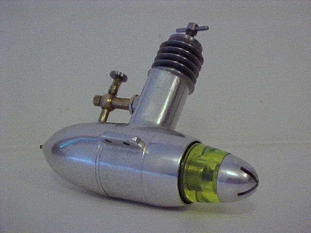
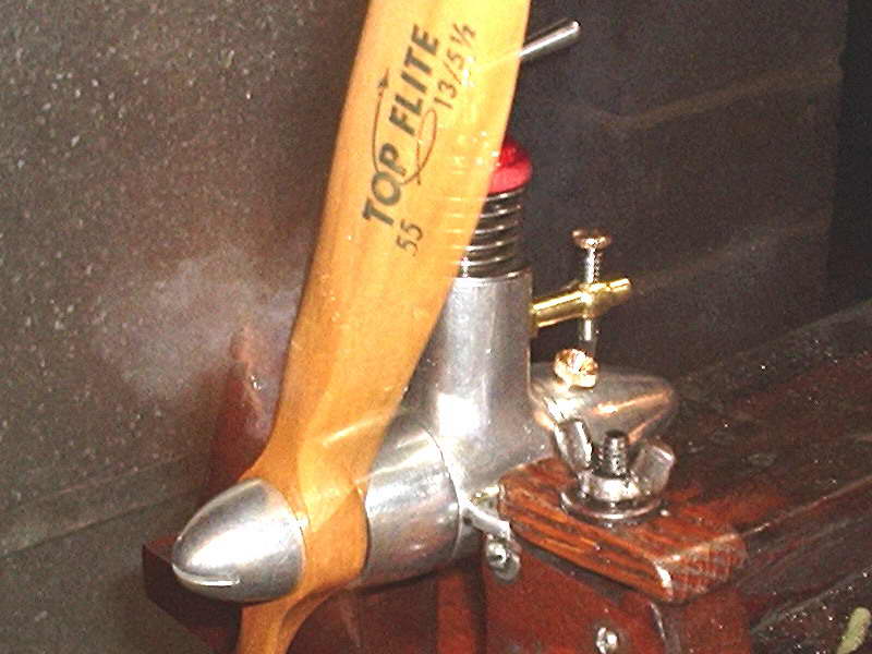 And certainly no beginner is Les Stone. The engine at the head of this page was built by Les in not much more time than I took do draft the CAD plans. Les' example moves the exhaust to the front of the engine like the Viking 2,5, another long-stroke diesel from Denmark that we rather suspect was designed by Mr Dommergaard. The photo here shows Les' engine running with the prop "stopped" by the flash. You can actually see through the prop is you look closely, and you can see a cloud of exhaust gas about to be swirled around and shot backwards.
Les built his example in roughly four weeks, without the aid—or perhaps that should be hindrance—of the CAD plans. The rest of us will go at it more slowly. Expect updates to appear here from time to time.
References:
| [1] | Laidlaw-Dickson, DJ and Russell, DA: Model Diesels, Petty & Sons Ltd, London, 1946, p27. |
![]()
