MATE Building Instructions - Page 8
- Centre the remaining aluminium stock and extend 35mm from the jaws. Face end, centre-drill and drill with ascending drills to Ø10mm x 16.5mm deep. Bore to nominal Ø16.5mm (a close, sliding fit on the upper cylinder) x 16.7mm deep. Finish turn to Ø30mm up to jaws. Support with the tailstock.
- Set the 1.6mm parting tool square to the spindle axis, retract the topslide to reduce tool overhang, traverse saddle to bring tool as close as possible to jaws for a test cut. Wind cross slide in to touch tool on Ø30mm and zero dial. Calculate final reading at 19.5mm and note.
Set spindle speed and feed rate to suit your lathe, the latter fairly coarse to avoid chatter. Lock saddle, apply coolant and commence to cut a test fin. Disengage feed just before Ø19.5mm reading and finish to size with hand feed. Zero dial. Correct any problem with setting and take another cut, after moving saddle 2.7mm to the right, this time down to the zero reading.
If you are experiencing problems with chips jamming on such a deep plunge cut, try backing the tool out several times. Any thing less than fine, even finning will marr the final appearance of your "MATE", so work out the best way to do the job and set your lathe accordingly. Three ways are suggested:
- a) Use a longitudinal saddle stop and appropriate twist drill shanks as spacers, inserting for example a 2.7mm drill between the stop and the saddle, locking the stop, removing the drill and advancing the saddle to the stop, and so on.
- b) Use the graduated leadscrew dial, or saddle wheel dial to advance the saddle.
- c) Lock the saddle and advance the topslide only. This is the least preferred option, as tool overhang may result in chatter with smaller lathes.
- Having chosen your method, retract the topslide back to minimise tool overhang and zero dial. Advance saddle until the flank of the tool touches the faced end. Zero leadscrew/ saddle dials. Retract tool from the face and advance the blade width plus the first fin width, 1.6 plus 1.6, or 3.2mm. lock all slides and cut the first fin. Advance the tool 2.7mm (1.6 plus 1.1), lock slides and cut second fin, and so on until you h,ave made six cuts.
- Chamfer the bottom of the first fin and break .the edge of the bore. Break the fin edges with a triangular file in an appropriate safety handle. Part the cooling fins from the stock at about 23mm from the faced end.
In the event your blade width is not exactly 1.6mm, recalculate the total length required to give you a top fin 4.5mm thick and decide how much to face off top. Centre the fins in the chuck with paper to protect the finish and extend 3mm from jaws. Face end and chamfer the top fin 45� x 1mm wide. Centre-drill and drill to Ø4.3mm. Using the tailstock for alignment, tap the M5 x .8mm thread for the compression screw.
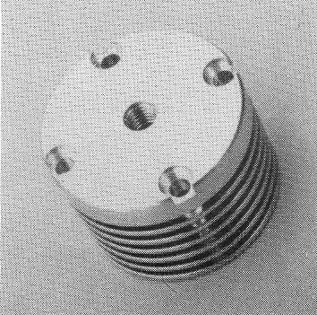
Advance rotary table to 0° setting, centre-drill each of the four holes in turn at 90° spacing. Starting at 0° again and taking care not to drill into a chuck jaw, drill each hole in turn Ø2.3mm, the tapping drill size for the 6BA cylinder screws. De-burr the cooling fins and screw jig and wash well.
If the torque required to turn the tap increases even slightly, is it swarf? Is it lack of lube? Or has the tap bottomed? Investigate and correct, as a broken tap at this stage is not a pleasant thought! When all holes are safely tapped, take crankcase from vyce and release the jig with a sharp tap on a piece of dowel inserted through backplate cavity. Clean all traces of adhesive from top face taking extra care not to mark the surface in any way.
This page is Copyright © David Owen 1989-2006. All rights are reserved world-wide.CYLINDER SCREW JIG (6-3)
DRILLING THE SCREW HOLES AND TAPPING CRANKCASE
COMPRESSION SCREW (6-2)
CYLINDER SCREWS (6-4)

Reproduction in any form without the written permission of the copyright owner is prohibited.