MATE Building Instructions - Page 6
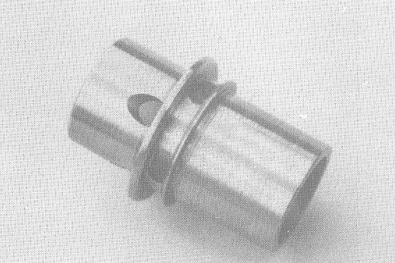
- Centre the remaining (15/16") steel stock in the chuck and extend 55mm from jaws. Face end, centre-drill and bring up tailstock centre for support. Finish turn to Ø16.5mm x 52mm long, facing shoulder squarely.
- Remove from chuck and scribe a line at 70mm from faced end. Chuck on Ø16.5mm and face off surplus to this mark. Re-centre accurately on Ø16.5mm, gripping only the first 20mm in jaws. Centre-drill and bring up tail-stock centre for support. Finish turn the stock to Ø22.5mm. Traversing to the right, finish turn to Ø19.5mm for a distance of 3.4mm from the shoulder. Using the 1.6mm wide parting blade, turn the exhaust belt Ø17.3mm x 2.4 mm wide.
- Face the Ø22.5mm to 13.6mm long, reducing diameter as much as possible without disturbing the tailstock centre. Finish turn the end to Ø17.3mm x 7mm long. Do not chamfer or break the edges. Remove tailstock, centre and drill the bore to a depth of 45mm, starting with a Ø5mm drill and ascending in small increments to Ø10mm.
- Set a boring tool with care and commence boring to drilled depth. Remove a maximum of .1mm at each traverse, altering feed rate and tool setting if necessary, to achieve a good bore finish by the time you have bored to Ø12.5mm. Continue boring to Ø13.2mm. Remove the last .1mm in maximum .025mm increments, traversing the bore three times at each tool setting to work any spring out of the tool, so that you end up with a round and parallel bore. The last operation prior to removing the blank (unported) cylinder, is to chamfer the bore entrance 45� x 1mm wide.
PORTING THE CYLINDER
- Mount the rotary table with 3-jaw chuck attached, on the milling machine table, to the left of the spindle, with the indexing handle facing you and over the table edge. The chuck axis is horizontal and centred accurately under the spindle axis. Lock "Y" (cross) axis and zero dial, noting direction of last movement, just in case. Mount a 3/32" slot drill in the spindle collet and lower the head until the tip of the tool is about 20mm above the chuck axis. Lock the head and lower the spindle now until the tip of the tool is about 5mm above the chuck axis. Lock the spindle in this position and set the depth stop, or note the dial reading.
- Loosely centre the blank cylinder in the chuck on the Ø16.5mm and then remove it. Turn the rotary table until one of the chuck jaws is vertical. Traverse the table to the right until the collet chuck just clears this jaw. Retract the spindle and carefully centre the blank cylinder in the chuck so that the slot drill is over the 2.4mm wide exhaust belt. Tighten the chuck firmly without crushing the bore. Make final adjustments with the "X" (longitudinal) table movement to centre the slot drill in the exhaust belt. Lock this slide and again zero the dial. Bring up a machine table tailstock, if you have one, or alternately support the overhanging end of the cylinder with some packing. Draw an arrow with a felt tip pen on the indexing hand wheel to clearly denote the direction used to advance chuck. Now advance the chuck to the0° setting and lock the table clamps.
- Re-check all settings and, when satisfied, switch on coolant and down feed the cutter at a minimum 2000rpm into the blank cylinder until it cuts through to the bore. Lock the spindle, slacken the rotary table clamps slightly and advance the chuck slowly to the 20 ° setting, then withdraw the cutter.
- Advance the chuck to the 90° setting and cut the next exhaust port, withdrawing the cutter at the 110 ° setting. The third port is entered at 180° and withdrawn at 200°. The fourth and last port is entered at 270° and withdrawn at 290°.
- Continue to index the table past 0° to 55°, this being the index position for the first transfer port. Lock clamps. Slackening only the machine table clamps, traverse the rotary table some 300mm to the left, away from the vertical spindle. Now tilt this spindle over at 45°, towards the rotary table and lock securely in this position. Mount a Ø4mm or Ø5/32" slot drill in the collet. (Do not use a twist drill which will wander on entry and exit). Traverse the rotary table back to the right and adjust the head height until the cutter is centred over the intersection of the lower flange face and the periphery of the Ø22.5mm. Reference to Drawing D2/05 will clarify this setting. Lock all clamps.
- Switch on coolant and downfeed cutter at 1500rpm into the edge of the blank cylinder, continuing to feed for 10mm, by which time you should have felt the cutter break through into the bore. Be careful not to continue the down feed into the tailstock support. Withdraw the cutter.
- Slacken the rotary table clamps and advance to the 145° setting, then re-tighten. Cut the second transfer port as before, repeating the operation at 235° for the third port and 325° for the fourth and last port. This completes the actual cylinder porting.
- Return the ported cylinder to the lathe, inserting 20mm only and centreing accurately on the Ø16.5mm. Bring up the tailstock support. Finish turn the lower cylinder around the transfer ports to Ø16.5mm (nominal) x 12 mm long. Face off squarely the cylinder seat flange, where it will seal on the top of the crankcase. Make the nominal Ø16.5mm lower cylinder a shakefree, sliding fit in the crankcase bore. Chamfer the lower cylinder edge 45� x 1mm wide and polish the cylinder 00 with #800 paper, lightly breaking all edges. Lastly, part off the cylinder from its chucking stub at 16.5mm from the upper flange face. Break the edge of the parted face with #800 paper and remove with a Swiss file any burrs raised during porting.
PREPARING THE CYLINDER LAP (5-4)
- The material for parts 18a, 18b and 18c is not furnished in the "MATE" kit. Ideally the cylinder lap (18a) should be made from copper, but brass or aluminium will do nearly as well.' Centre stock in chuck, extending some 65mm from jaws. Turn the material to Ø13.5mm, face end, centre-drill and support. Drill Ø4.3mm x 20mm deep and tap M5 x .8mm with a taper tap, for a depth of roughly 12mm.
- Purists may wish to slit the lap with a slitting saw in the mill, however it is easily done by hacksawing whilst held in the chuck. Scribe a line along the length of the lap with a tool in the toolpost. Lock the spindle or place lathe in back gear. Carefully saw along your line, across the centre of the lap, for 30mm from the faced end. Remove from chuck and de-burr along the sawcut with a scraper. Run the taper tap in again to clear the thread. Wash lap thoroughly and screw an M5 socket head grubscrew in until resistance is felt. Do not expand the lap.
- Re-chuck and finish turn to a close fit in the bore for about 42mm from the faced end and turn the shank to Ø11mm as shown.
LAPPING THE CYLINDER
- Centre the lap in the chuck, gripping it on the stub end. Move the saddle right out of the way. Cover the lathe bed with plastic wrap and rag to prevent any contamination from the lapping abrasive. This is a household metal polish, called Brasso in Australia and used, funnily enough, for cleaning brassware. Any similar polish should work. It's not as fast as diamond paste, but used with patience will result in an excellent job. Forget valve-grinding paste, by the way. Aluminium Oxide powder in 500-800 grit may be used and will cut faster than Brasso.
- Transfer some Brasso to the lap and one drop of thin oil. With the top end facing the chuck, slip the cylinder over the lap. Some resistance should be felt, but you should be able to turn the cylinder on the lap fairly easily. Grasp the cylinder between the thumb and index finger wiith a strip of leather, making sure that the surplus material is held well clear of the chuck jaws.
- Now you have a good idea of the amount of torque required to restrain the cylinder, discard the leather and hold the cylinder in your fingers only. Wash the cylinder and lap each time you expand it. Be careful not to expand the lap too much, or the cylinder will become too hot to hold and may jam on the lap. Beware of the spinning chuck jaws at all times! Continue to lap the cylinder, stroking it back and forth without rocking it from side to side. The stroking should incorporate a spiral motion, twist in your wrist as you stroke at about one stroke per second. Make sure the cylinder does not run over the cutting length of the lap by more than 10mm at each end, otherwise a bell-mouthed bore will result.
- When you have an acceptable surface finish, again very thoroughly wash both the cylinder and the lap, having removed the latter from the lathe. The lap should have an even wear pattern towards the front, tapering away to the chucking end. This is quite normal, as this simple type of lap does not expand parallel. Now slip the top end of the cylinder over the lap and expand it with the grubscrew until it is a close fit in the lower end of the bore. Using the lap as a simple gauge, withdraw the cylinder slowly and feel for any noticeable change in the bore size from one end to the other. Ideally you will have introduced a taper at the lower end. If the top end is bellmouthed you're in strife, but we'll rectify that condition in a moment.
- The final lapped bore will be round, with a relatively smooth, matt surface finish and will taper inwards from the bottom towards the top. This is achieved from a parallel bore by selectively lapping the lower end. Slip the top end of the cylinder over the lap, and lap as before, stroking the top end 10mm past the lap, but shortening the stroke so that the lower end does not extend past the lap. The spindle speed can be increased to 500rpm. Continue to lap and test as before, until the lap (as a gauge) will smoothly enter the bottom of the bore, but start to tighten up as it passes the exhaust belt, finally jamming towards the top end of the bore.
If you have bellmouthed the top end, you will have to selectively lap the bore to correct this, until the bore is parallel at least down to the exhaust belt. Then proceed along the lines above. When lapping is completed, wash both cylinder the and the lap thoroughly to remove any traces of abrasive. Clean the lathe too at this stage. Measure the lower cylinder bore and note this dimension on the piston drawing.
Start the lathe at 250rpm and traverse the cylinder back and forth along the lap, running it over a maximum of 10mm at each end of the lap. Stop as soon as the torque resistance drops to zero. Wash the cylinder thoroughly and wipe the lap clean. Tighten the M5 grubscrew until resistance is again felt between the two parts. Re-coat with Brasso and oil and repeat the process.
The amount of time it takes to achieve a round bore with a good surface finish is determined in the beginning by the original bored finish. However, the longer the cylinder is lapped to reach a suitable finish, the greater the chance of bellmouthing the bore. When you have lapped the cylinder some seven to ten times, wash it very thoroughly and inspect the surface finish under a strong light. It should be smooth and dull grey. There may be a faint trace of tool marks from the boring operation, but to continue lapping in an attempt to remove these entirely may result in the problem mentioned above.

This page is Copyright © David Owen 1989-2006. All rights are reserved world-wide.
Reproduction in any form without the written permission of the copyright owner is prohibited.