Backplate
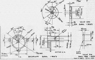 Chuck the piece of dural 1-1/2 inch diameter x 2 inch long in the three-jaw chuck so that it projects one (1) inch from the jaws and face off. Center drill, the drill 7/64 inch and ream 1/8 inch diameter using kerosene or fuel oil as lubricant. Lightly scribe center lines with tool point and, while it is still in lathe, mark out with steel rule and scriber to locate the intake center. Make heavy center pop mark at this point.
- Using highest spindle speed and finest cross feed with sharp round nosed tool and well lubricated light cut, reface end, taking care not to eradicate center pop. Clamp scriber in tool post and lightly mark out intake segment to drawing, using a dividing headstock, or the chuck jaws and a protractor as guide.
- Turn outside diameter down to a snug slip fit in crankcase for a length of 7/32 inch and face shoulder to good finish. Cut off 29/32 inch long with well lubricated cut-off tool, having plenty of top and side clearance.
- Drill and ream intake hole on center pop mark.
- Taking great care not to damage the finished valve face, saw away the bulk of excess material around the intake.
- Turn up mandrel for intake bore and set-up back outward. Turn and face back to drawing.
- Mark out the bolt hole centers and lugs to the drawing and saw and file to match crankcase. Carefully file intake segment to achieve a smooth blending with intake bore.
- Drill a hole to suit the spraybar unit at desired angle (1/8 inch drill used on the prototype for a Cameron .09 unit, with fiber washers).

Valve Disc
- Set up the piece of 1 inch diameter dural remaining from prop driver in the three-jaw chuck. Center drill, drill and ream 1/8 inch diameter and face. Turn OD to the drawing and mark out, using tool and headstock, for valve opening and drive recess center. Cut off to the drawing thickness plus 1/64 inch.
- Saw and file balance step and valve opening; drill and flat bottom drive recess.
- Turn up mandrel for center hole and, using very light cuts, face in similar manner to backplate, down to drawing size.
- Reverse on mandrel and bore recess for valve pin head.
Valve Pin
Turn from 3/16 inch drill rod to press fit in backplate, striving for best possible finish on small diameter. If necessary, lap valve disc to running fit on pin. An early McCoy .19 valve pin can be used if desired.
Assembly
This operation will be self-evident by the time you have completed the components; however thoroughly clean and oil everything before finally putting unit together. The valve unit can be improved by fitting a McCoy .19 rotor shim and, with or without, the pin should be pressed in until the disc revolves with a slight stiffness.
No backplate gasket should be necessary, but a .005 inch gasket of fiber or soft copper should be fitted at the lower cylinder flange joint.
You will find minor differences between the illustrations and the working drawings, made to simplify construction.
