 |
 |
 |
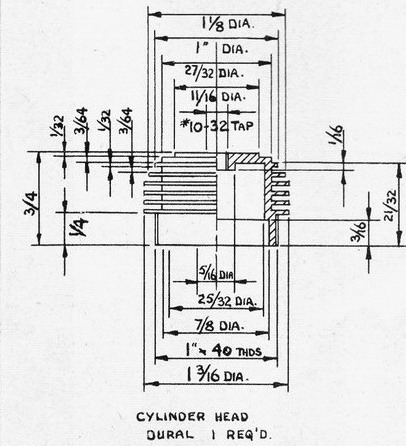
Cylinder Head
Little need be said of this part, other than that the bottom edge must be faced on the same set-up on which the thread is cut to insure even pressure on the cylinder flange when tightened.
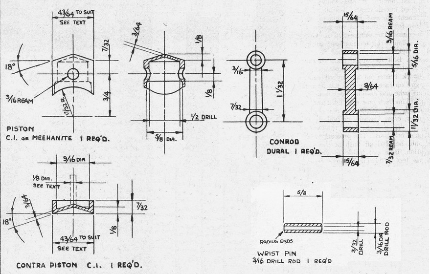
Wrist Pin
From 3/16 inch diameter stock drill rod; the radiused ends should be polished with fine emery paper after drilling.
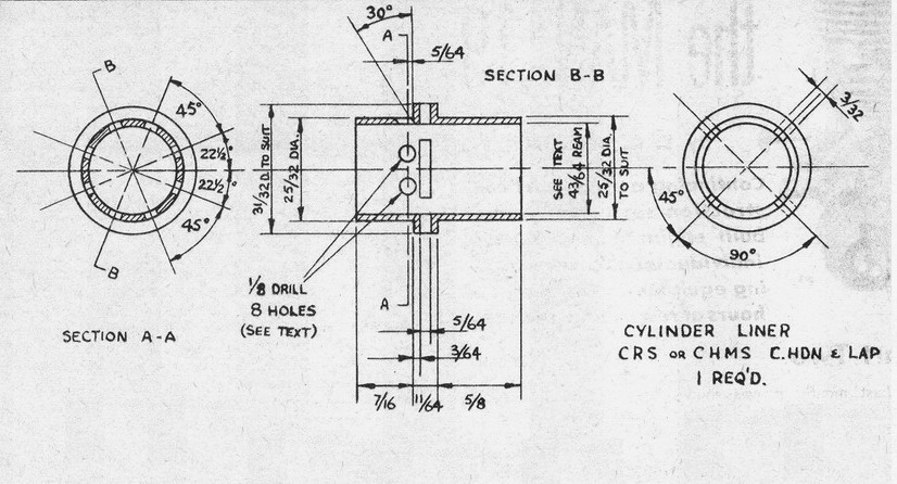
Cylinder
- Chuck material remaining from crankshaft in three-jaw and drill, bore and ream, with fine feed and lots of oil, to 43/64 inch diameter. Turn up a mandrel to suit and complete machining of the component, lightly chamfering top and bottom of bore, making exterior of upper portion to a snug slip fit in cylinder head. Mark exhaust and bypass centers circumferentially with a fine tool point in the lathe. Complete radial markings in lathe, using using dividing headstock if fitted, or the chuck jaws as a guide if not so equipped. Remove mandrel from lathe and use as means of clamping in vise, etc while drilling ports.
- The exhaust ports are produced by drilling and filing. Therefore, make appropriate center pop marks and drill a series of 1/16 inch holes. Similarly, drill 1/8 inch holes for the bypass ports. Remove work from mandrel and using a 1/16 drill in each of the exhaust holes carefully waggle drill sideways in order to break through each hole in such a manner that a small hacksaw blade or point file can be inserted. Patiently file ports to the drawing.
- Having completed the exhaust ports, put a 1/8 inch drill through each bypass port in turn and, observing the inside of the bore, carefully incline the drill in such a manner as to slant the holes upward until their top edges are 0.025 inch below the lower edge of the exhaust ports. This is much easier than it sounds and can be gauged quite accurately by squinting through the opposite exhaust port. A final, though not essential refinement is to file the upper edges and sides of the bypass ports square, to increase the initial opening area.
- You have the choice of using the cylinder liner soft or case-hardened. If possible, have it carburized for a half-hour in a cyanide bath and quenched in oil, having first removed all burrs inside and out from port cutting.
- Finishing the bore round and parallel can take a variable amount of time depending on the smoothness of the reamed finish. During hardening, the bore may distort slightly and finishing may take a considerable time; however, the smallest automotive shop usually uses Sunnen honing equipment for wrist pins and, if approached in the right way, the man in charge will have a hone run through the bore in return for a look at the engine when completed. That is the way it worked for us and a few minutes spent in describing the mysteries found an amused and interested listener who did his best to produce a good job. The Sunnen principle, with a little care, produces a dead round and parallel hole and it is no exaggeration to say that the model engine industry was made possible by this machine.
- Either after honing, or straight from reaming, the bore should be lapped to a mirror finish. A piece of 3/4 in diameter copper, brass or soft aluminum about 1 foot long should be chucked, centered and supported by the tailstock and turned to a snug slip fit for the cylinder bore. Cut a series of shallow grooves 1/32 inch wide, about 1/4 inch apart, along its entire length and remove resulting burrs. Coat the lap with fine lapping compound and, running the lathe very slowly in back gear, move the cylinder back and forth along the full length of the lap until a high uniform finish is obtained. Try not to exert any tilting pressure on the cylinder with the hand. Finish the surface with a mixture of oil and metal polish or rouge, having first cleaned off all compound from cylinder and lap, until the bore is mirror-like.
Piston
- Chuck the piston material in the three-jaw and machine the inside to the drawing. Turn the outside diameter to size plus 1/32 inch and chamfer the end 1/32 inch x 45°. Cut into the material on the same set-up so as to form the piston crown, but leaving about 3/16 inch diaemeter in the center still holding the work to the stock.
- Using a round nosed tool at high speed with very fine feed, turn the OD progressing with light cuts until the chamfer on the cylinder bore begins to lock with that on the piston skirt. Now proceed extremely carefully, taking the tiniest cuts possible until the cylinder can with difficulty be eased onto the piston. Clean and oil both components thoroughly and then, holding the cylinder firmly, work them together with the lathe running, taking care not to let them grip. After a short time they will slide with very little resistance, but will grip if relative movement ceases. At this point they are ready for use.
- Remove stock from the chuck and grip in the vise. File curve in skirt to drawing and drill wrist pin hole 11/64 inch diameter and ream to 3/16 inch with stock resting in Vee-block. Saw the piston from stock, clean up the crown with a file and remove all burrs.
Con Rod
- Take the 1/2 inch diameter x 3 inch dural rod and cut in half. Chuck one piece in four-jaw lengthwise so that center comes in roughly mid-length position and the ends in relation to the chuck jaws show the material to be at right angles to the bed. Face 1/8 inch off and remove from chuck.
- Rest stock on flat and center pop bearing centers, taking great care to assure accuracy, and drill and ream to drawing, making sure both bearings are parallel.
- Turn up mandrel for big end and finish-machine both faces as far along the shank as possible before slippage occurs.
- Turn up mandrel for small end and repeat Stage 3.
- Remove from mandrel and saw and file to finished dimensions.
- Fit bearings to crankpin and wrist pin, lapping if necessary.
Contra Piston
- Set up remaining piece of cast iron or Meehanite, projecting 3/4 inch from three-jaw, and face and chamfer 1/16 inch x 45°. Turn OD down to 11/16 inch diameter and, using round nosed tool with the lightest possible cuts and testing with cylinder between each, carefully work down until cylinder will grip. Clean and oil both parts and try again. If the cylinder seems likely to go at a light tap, the contra piston OD is probably satisfactory.
- Finish-machine to drawing and remove burrs on same set-up, but cut into stock behind component so as to leave a 1/8 inch diameter shank about 1/2 inch long, and cut off.
- Try part in cylinder and tap lightly into position taking care not to tilt or jam the parts. At this stage the engine can be partially assembled and it will be found that the 1/8 inch shank on the contra piston will project through the compression screw hole in the head. Clamp a prop onto the crankshaft and, with a little oil in the cylinder, flip prop to check that contra piston moves without using excessive force when a hydraulic lock occurs. Tap the shank end and flip repeatedly until satisfied, then remove head and check for compression leakage past contra piston. If the fit is definitely too tight, the 1/8 inch shank can be used for chucking, while the OD is eased slightly with a small oilstone. It is unwise to use emery paper. Having achieved the desired fit, the shank can be removed and the part gripped lightly in the chuck for cleaning up interior.
Compression Screw
This part is not detailed as it simply consists of a 10-32 steel screw with a music wire tommy bar soldered in the slot and can be made to any desired length over 1/2 inch.
