The toughest part of the job is the crankcase and for that reason alone we will tackle it first. Before marking out, we need two adjacent faces dead flat and at right angles; therefore, set the workpiece in either a three-jaw or four-jaw chuck, depending on whether you have a piece of round bar or a block, and clean up one face. Next, use this face as a seating on a right-angled plate bolted to the face plate and clean up the adjacent face which will eventually be either the back, or the top, of the crankcase.
 |
 |
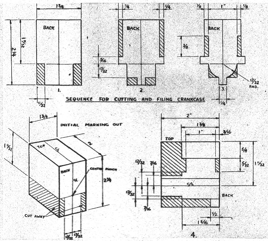
This accomplished, You can start marking out. First step is a center line on both faces. If you are using a piece of 2-1/2 inch round, the dressed end will be the back and the 1-1/4 inch wide flat you have machined will be the top. If a block, the 1-3/4 x 2-1/4 inch face will be back and the 1-3/4 x 2 inch will be top. Mark the faces accordingly with the scriber. On the back, exactly 1-11/32 inch from the top, scribe a line intersecting the center line at right angles. Lightly center punch the intersection. Next, scribe a line on either side of and parallel to the center line on the back, 17/32 inch away from the center line and extending only from the cross line downward. The diagram will make this clear and illustrate the portions to cut away, but before doing so, mark a line on either side of the 1-11/32 inch piece from the top and check its truth from the back with a set-square.
Great care should be taken with the marking to insure accuracy. Its purpose is to establish the underfaces of the beam mounts exactly 1-11/32 inch from, and parallel to, the top face of the workpiece, as the mounts will be used as a datum and location for all subsequent machining of the crankcase. The diagrams illustrate the other successive stages of marking and cutting in order to achieve the rough crankcase shape, which, while an unpleasant and laborious business, will remove most of the donkey work included in the job and clears the way for the more skilled and interesting steps described in sequence, below.
- Mount the roughed-out workpiece by its beam lugs to a right angle plate, back face outward, and clamp securely. Bolt the angle plate to the lathe face plate with the center line of the workpiece on dead center. Check with tailstock center on workpiece center punch mark and set square on face plate and. top and side faces of workpiece. Start lathe and double-check visually.
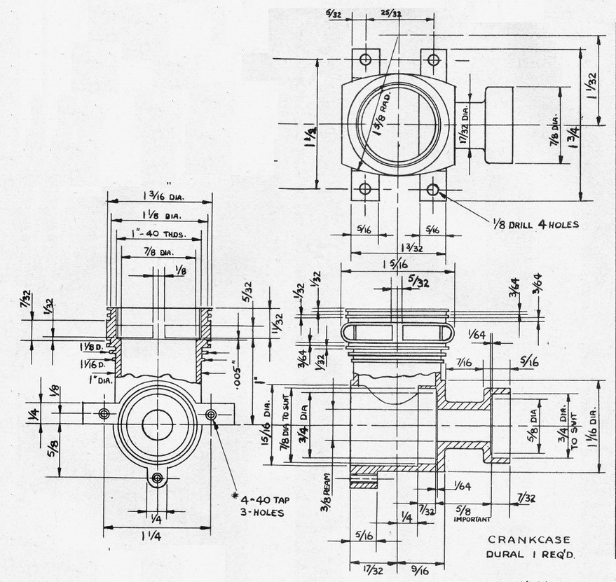
- Skim back face with light cut, center drill; drill straight through with 23/64 inch diameter drill; ream with 3/8 inch diameter reamer, using kerosene or fuel oil as lubricant. Reface back 1-1/2 inch diameter by 1/8 inch deep, thus establishing the final back face of crankcase. The projections left on the mounting lugs should be filed off flush at the end of this matching operation. Bore out inside of crankcase to drawing dimensions less 1/64 inch. Remove face plate from lathe and remove workpiece from angle plate.
- Fit three-jaw chuck and very firmly clamp a piece of 5/8 inch diameter x 3-1/2 inch scrap steel rod, leaving about 2 inch projecting from chuck. Carefully turn a 1-1/4 inch long mandrel to secure binding fit for the 3/8 inch diameter reamed bore and, when quite sure that the crankcase is firmly mounted, finish bores to drawing dimensions, using the 7/8 in: OD ball bearing as a plug gauge for the bearing housing. Take great care over this operation, using very light cuts until the bearing begins to enter the grip. The final dimension should be .001 inch under the bearing diameter if you have suitable gauging equipment.
- Reverse the crankcase on the mandrel and rough and finish bore the outer bearing housing, again taking great care. The 5/8 inch dimension between the two bearing housing inner faces is most important and is best achieved by measuring the original amount of metal to be removed and then boring to the required depth. You can actually go between dead 5/8 inch and plus-l/64 inch on this dimension without getting into trouble and it is safest to aim at the high side. A slight error can then be offset in the crankshaft machining. The exterior of the front crankcase portion can now be finish-machined and the workpiece removed and checked, particular note being taken of the final bearing housing spacing.
- Replace face plate and angle plate on lathe and mount the crankcase on its back face with the top pointing toward the tailstock. Clamping can be accomplished by bolts and washers through the main bearing, but do not over-tighten. The back face should be exactly 17/32 inch below dead center, and the undersides of the beam mounts parallel to and equidistant: from the face plate. Check carefully and then skim the top face of the crankcase to exactly 1-11/32 inch from the underfaces of the mounting lugs. This is vital as subsequent machining will be gauged from the top face. Center drill and drill through about 3/8-1/2 inch diameter, using very light feed and plenty of lubricant so as not to disturb workpiece, and bore out to 7/8 inch diameter to a depth of 7/8 inch Next, bore exactly 31/32 inch diameter to a depth of exactly 11/32 inch and screw-cut 1-40 threads down to within 1/8 inch of shoulder. We used 60° thread form as this gives a .015 inch deep effective thread. Now take a .005 inch skim off shoulder and the interior is finished. Rough and finish exterior to drawing and remove from lathe. This completes .the crankcase machining.
- The exhaust stack is most easily hollowed with an endmill, but not possessing the, luxury of a milling machine, we drilled a series of 1/8 inch holes and filed out the remainder by hand, taking great care not to mark the surface of the inside shoulder. The exhaust stack spacers of 1/8 inch and 5/32 inch should not be reduced in size as they hold the top and bottom of the engine in opposition and take the firing stresses in tension. Likewise, the exhaust stack wall thickness should not be reduced, but, if anything, left on the thick side. The mounting holes and backplate retaining holes can now be drilled and tapped to complete the component for test purposes. The fancy bits of filing, etc necessary to produce a finished lightweight crankcase can wait until you are satisfied with the operation and performance.
