Building the Little Dragon Page 2
Click on a photo to view it larger size.
Crankcase
The little Dragon was described by the designer a using "sleeve-in-block" construction. With the sleeve complete, we can now machine the block from a length of 3/4" square aluminium. While any grade will do, I prefer 2024 as it machines well to an excellent finish and does not tend to build-up on the cutting edge of the tool as softer grades do. A section 1-7/8" long provides enough excess for comfort.
 Crankcase 1.
 |
 Crankcase 2.
 |
 Crankcase 3.
 |
 Crankcase 4.
 |
 Crankcase 5.
 |
 Crankcase 6.
 |
 Crankcase 7.
 |
 Crankcase 8.
 |
 Crankcase 9.
 |
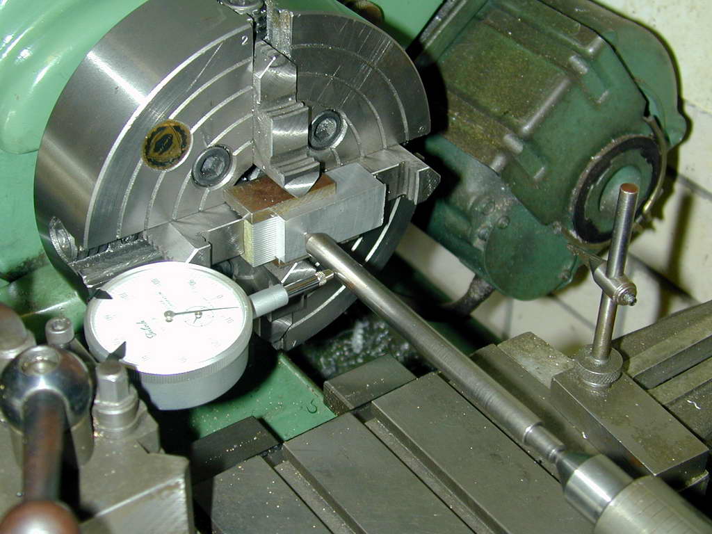
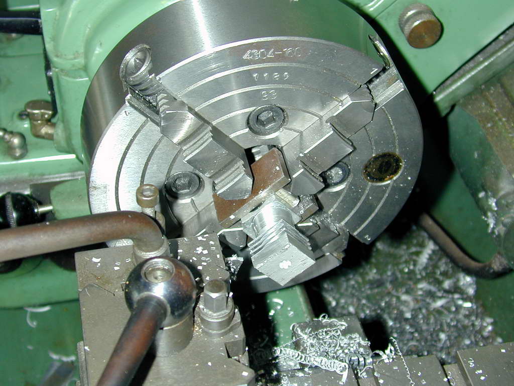
- Layout comprises 5 scribed lines; the first close to what will be the bottom of the case. The remainder are measured from this at 3/8", 3/4", 1-1/4", and 1-21/32". A center-pop mark is then made in the middle of the block on the second line and the block setup in the 4 jaw chuck with a "wobbler" to get the block to run true. It's important that the blind bore we're about to make is at 90° to the axis of the block so that the crankshaft and cylinder are correctly aligned for minimum operating friction. In this photo, I've reversed two of the chuck jaws and pressed the bar firmly back onto the jaw faces to achieve this. Be careful when you do this that you can still drill through the centered block for the rotor pin and not hit the reversed jaws!
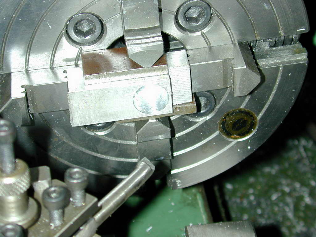
- The block is center drilled, then blind drilled about 1/32" short of final depth in stages: 1/4, 3/8, and 19/32". I then used a 1/2" slot-drill (2 flute cutter) to flat-bottom the hole, but the boring tool could do the job just as well. The hole is now opened out to 5/8" diameter and 9/16" depth. Be careful to get as good a finish as possible on the inner face of the hole as this is the rotor seat. The 3/32" hole for the rotor pivot is then drilled. Drill undersize--say 5/64"--first to get the hole close to size.
- Finally offset the topslide 45° and "break" the edge to ensure the front case section will be a close fit (ie, allow for the inevitable tiny radius the tool will produce on the shoulder of the front part). Also not the packing pieces used under the jaws when working with the case. These are to prevent the jaws marking the work.
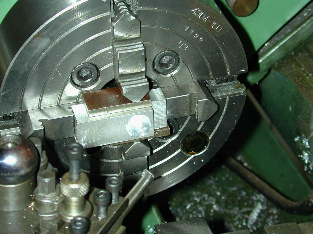
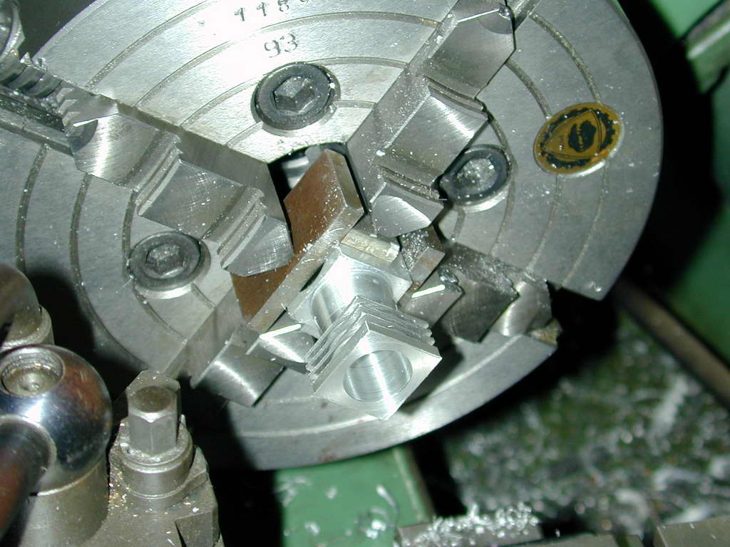
- The chuck jaws are returned to normal orientation and the bar setup to bore for the cylinder. Again, pieces of packing protect the case surface and one bridges the bored hole. Make sure the scribed line at the 3/4" mark can be machined down to comfortably. I've used a plunger DTI to center the block. Rest the plunder against a face and rock the spindle to obtain a minimum reading, then adjust the cross slide to zero the DTI. Wind the DTI off the work, rotate the chick 180°, than lift the plunger and wind back onto the part. Note the deflection from zero, figure out which way the jaws need to move to correct it, then adjust to split the error. Re-zero and repeat to check the opposite side. Do this until the measure difference is under a thou with both jaws tight (but not crushing tight). Now repeat for the other two faces.
- Now do as I say, not as I did
 . Turn the lower section to 11/16" diameter between the scribe marks. Now face back to the top scribe mark, and cut a cooling fin groove to leave a top "fin" 1/8" thick with a 1/16" wide parting tool. Measure the exact width of the groove your tool makes, and the length of the section under this groove. Now figure out how thick the three fins will need to be to equally space them out and cut them, taking it slow especially while taking the interrupted cut on the bar corners.
- The next step would be to turn a blind bore 0.881" deep to be a close but sliding fit on the finished liner. It should be possible to pull the liner out, but not for it to fall out by itself. Too bad you can't check this until it's too late. Note that the bottom of this bore locates the liner and sets the timing. But accuracy depends on where the axis of the shaft bore is in relation to the top of the case and hence, how well you marked out and set-up.
There's no photo for this, but we now have to drill and file a transverse slot for the conrod. This is time-consuming, tedious, and seriously not-fun, but we've got no choice. We can't drill through and still leave a "seat" for the liner as this would destroy the rotor seating face. Roger Schroeder and Tom Crompton side step this by making the rotor seat a separate part like the front bearing section. While it means tapping another four blind holes, it think it's a better design that easier to make and also allows the rotor seat face to be lapped. But if you are going to be a purist, out with the needle files and take care not to injure either of the turned bores while you are at it.
Reverse the case in the jaws and face back to split the lower scribe line. We'll see how accurate your mark-out and set-ups were on the next page.
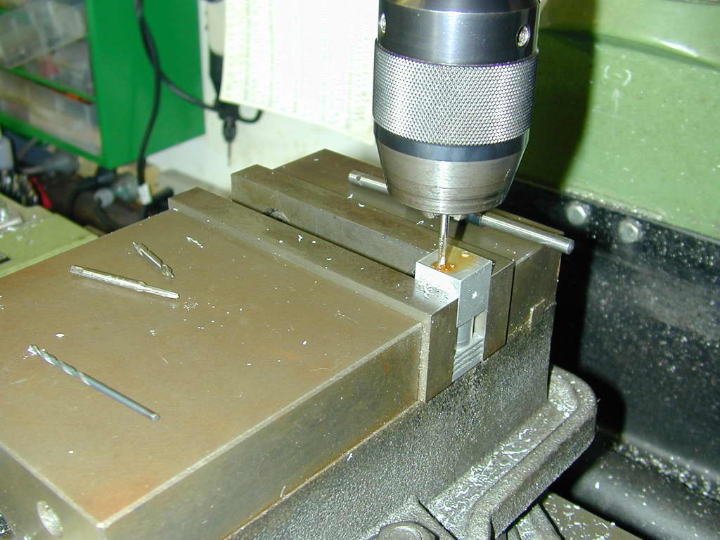
- This shot shows the holes for the mounting studs being drilled and tapped. The MAN plan calls for a 3-48 thread, but a 4-40 could be substituted. Just be careful not to drill too deep because you'd break into the case cavity and will probably loose primary compression around the thread.
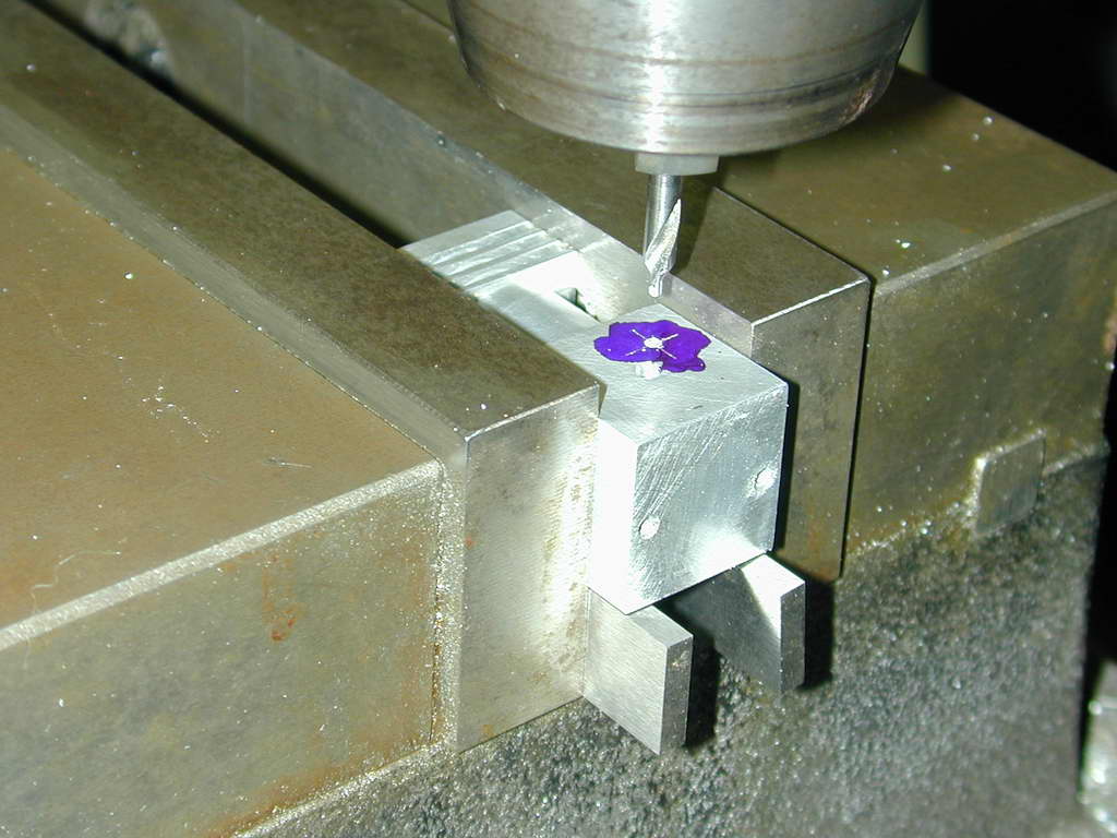
- The hole for the inlet tube is drilled on the 45° radial such that it is centered on a 5/16" pitch circle diameter (PCD). It's location will impact inlet timing, and move it too far out and the rotor won't seal it off correctly. The MAN instructions postponed this step until the rotor was available which is not a bad plan. The inlet is just a length of 5/32 brass tube, tapered to be a press fit in this hole. I used a 5/32" hand reamer to taper the hole and got a press fit so good, that I could not pull the tube out without fear of damage! So I made a feature of it and used the case with tube firmly inserted to align for drilling the spraybar hole.
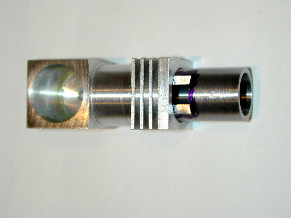
- This shot shows the liner being inserted into the crankcase. The exhaust opening needs to be cut so it's top is level with the bottom of the lower cooling fin. as noted in my critique of the design, this places the opening 1/32" too low to match the liner. This does not really matter, but it's ugly. We can't really raise all the fins as this would make the top fin only 3/32" thick--marginal for the cylinder head hold-down screws. A better solution would be to increase the height of case and liner by 1/32", adjusting the head to still provide the correct compression ratio, but further raising the plug element from the combustion chamber unless the plug seat is lowered by counter boring. You probably now see why changes that are not fully thought through are not such a good idea.
Anyway, at this stage we are done except for the 2-56 tapped holes for head and case-front. These will be left until we've made these bits and can drill and tap them together to assure alignment.