A Flash Steam Plant
By F.J. Camm
(click on images to view them full size)
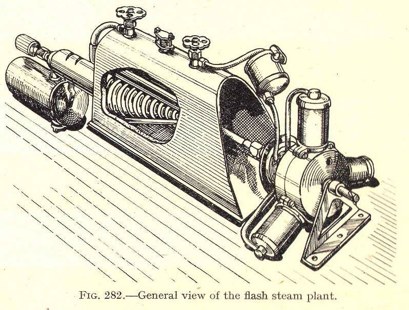
The flash steam plant described in this chapter has been designed by me, and is capable of flying a model aeroplane weighing 3 pounds. There are three cylinders measuring 1/2 inch in the bore, with a stroke of 1 inch. The engine and boiler weigh 15 ounces and the blowlamp 3 ounces.
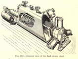
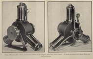
Fig 282—General view of the flash steam plant.
Weight and Horse-power
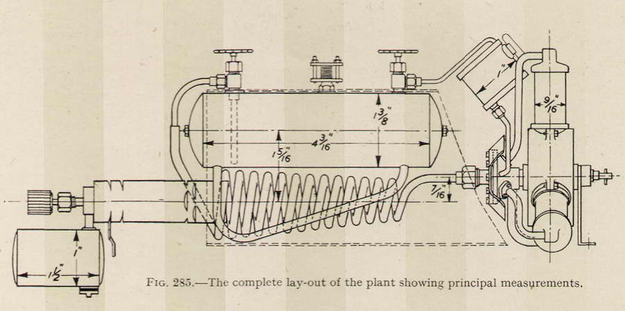
Fig 285 shows the whole layout of the plant. First take the engine as shown; with three cylinders each of the bore and stroke-mentioned. The generator is to supply steam at a pressure not lower than 150 lb. per sq. in. This should drive the engine, with a propeller of reasonable diameter and pitch, at about 1,500 revolutions per minute. At this speed and pressure the engine will develop about .2 horse-power and have a total weight with fuel, water, and oil, of approximately 0.875 lb which is 4.37 lb per h.p.
The Working Principle
Before dealing with the details of construction of each part it will be advisable to outline the principle on which the plant works. Commencing with the furnace; this consists of a fuel container, which fuel is ordinary petrol, a needle valve for regulating the supply, three nipples or nozzles of the size which is standard for small blowlamps, a three-ported shutter covering the nipples, the object of which shutter will be explained later, and a perforated mixing tube.
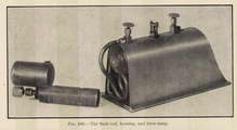
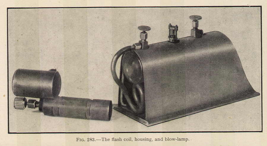
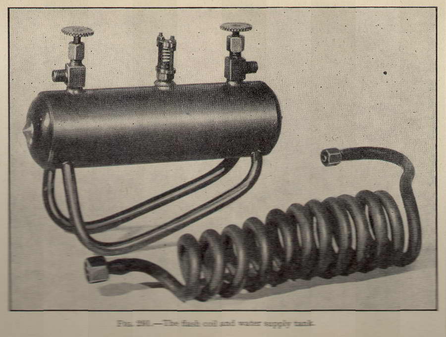
Fig 283—The flash coil,
housing and blow-lamp.
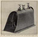
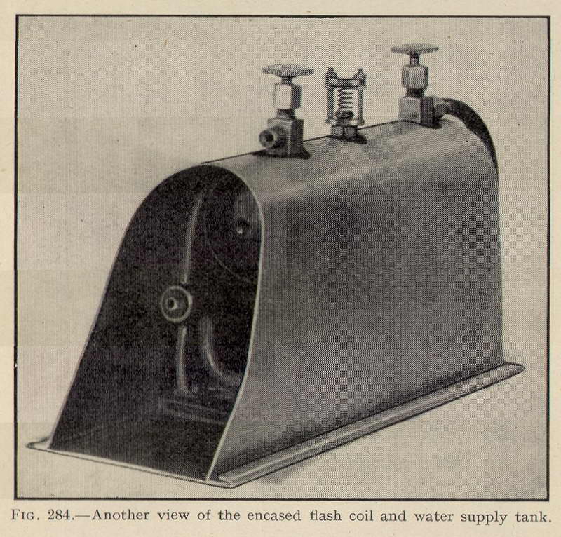
Fig 284—Another view of the encased
flash coil and water supply tank.
The steam generator consists of two parts: (1) A shell boiler fitted with two water tubes and a safety valve, and (2) a flash coil of steel tubing. Now the shell boiler does not supply steam to the engine, but is utilized only to generate pressure and deliver the water contained in the shell, at the said pressure, to the flash coil, where it is converted into steam which passes to the engine. In all steam plants previously made the water to the flash coil was supplied from a tank under air pressure. Not only was the water cold, but the delivery pressure varied from perhaps 100 lb. at the start to practically nil before the water had gone. In the present case, as the pressure in the shell boiler will be 150 lb. per sq. in., the water will pass to the flash coil at a temperature of about 350 F. and, so long as any water remains in the shell, the pressure will be constant. A wheel valve is provided for regulating the water supply to the coil.
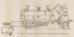
Fig 285—The complete layout of the
plant showing principal measurements.
It will be seen from Fig 285 that a second wheel valve is fitted on the top of the boiler shell. A pipe from this leads to a small tank containing lubricating oil, which oil is delivered in minute quantities to the cylinders of the engine. Although the lubricant is more or less injected into the ports from the valve face, it has not to be forced in against steam pressure from the flash coil, but as there will be some exhaust steam to contend with, it will be necessary to have pressure at the back of the oil, hence the arrangement shown.
At the present stage the engine does not call for description, but there is one feature in the plant which must be referred to. It will be obvious that as the control of the fire and water will pass out of the hands of the operator as soon as the machine begins to fly, some means must be provided to guard against the possibility of burning the flash coil through evaporation of all the water before the fuel is consumed.
Synchronizing Water and Fuel
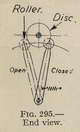
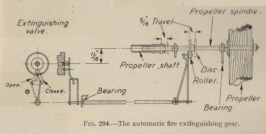
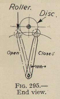
It would be possible by actual test to so time these two, by putting a definite quantity of fuel into the tank, that the petrol is all consumed just before complete evaporation of the water, but as the same fuel is required to first raise steam, perhaps from the cold, in the shell boiler, one cannot be always sure that the two will be emptied at the same time, so the shutter or extinguishing valve has been devised, shown in Fig 294, which when suitably operated will cover, all together, the three nozzles of the burners. The method operating this shutter is simple; the propeller spindle is so designed that it withdraws from the tubular propeller shaft in order to allow the airscrew to free-wheel. The spindle will carry a revolving disc, and when the propeller and discs are being driven by the engine there will be a small roller, carried on the end of a spring-loaded lever, running on the periphery of the disc. The lever is attached to a light shaft which will run along to the burners. At the burner end there will be another lever engaging with the arm on the extinguishing valve.
As long as steam is passing to the engine it will drive the pro�peller, but as soon as the engine stops, from lack of water in the flash coils, the air drag of the propeller will cause the spindle to slide in its bearings, the roller will pass off the disc and the spring referred to will cause the levers at both ends of the shaft to move; the one at the fire end will operate the extinguishing valve, so shutting off the petrol gas, and thus save the destruction of the dry flash coil.
Heat Insulation
In order to protect the machine from the heat of the furnace, the whole of the steam generator is to be encased in thin sheet metal and this is to be well lined with asbestos card�board. The end of the mixing tube of the blow-lamp will be intro�duced through a hole at the end of the casing opposite to the centre�line of the coil. At the other, the engine end, the casing is divided to form three openings, each of which will come opposite to the three cylinders. Thus, the cylinders will have circulating around them the hot gases as they leave the furnace or firebox, and so the losses from condensation until the steam has done its expansive working will be reduced to a minimum.
It will be seen, therefore, that throughout the plant the thermal efficiency should be high, and the only trouble likely to be experienced is the possible carbonization of the lubricating oil. Nothing of this sort is anticipated if a good high-temperature oil is used.
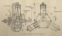
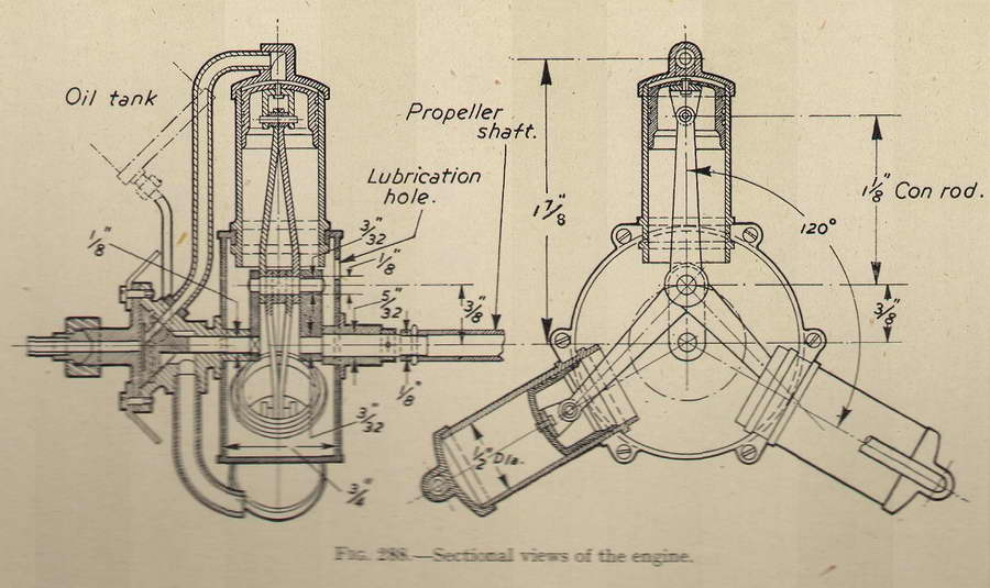
Fig 288—Sectional view of the engine.
The Engine
Coming now to practical details, commence with the engine. This is shown by two sectional drawings in Fig 288, that on the left-hand side being through the centre line of the crank�shaft, and that on the right a cross section through the centre of the crankcase and two of the cylinders; the third cylinder being shown entire.
In this engine no soft soldering will be permissible, everything which is not to be detachable must be silver-soldered. So, as pro�vision must be made for assembling in an orthodox manner, the crankcase is to be made in two halves, the parting being on the circumferential centre-line, and the joint secured with six cheese�headed screws passing through lugs as shown. This arrangement provides a means of fixing the cylinders and makes it possible to assemble all the working parts-crank, connecting rods and pistons -without difficulty. Then each cylinder is passed over its piston, and the halves of the crankcase screwed together, clamping all three cylinders in place.
This end is achieved by having in each half-crankcase three cylindrical rings between the three pairs of lugs. To receive these, each cylinder has two rings silver-soldered to them, the space between the rings being a perfect fit over the half rings on the crank�case halves.
The Cylinders
The cylinders are made from steel tubing bored and lapped out, and the pistons, of gunmetal, are lapped into them. The pistons have no packing rings, so they must be a .very perfect fit in their cylinders. To render them still less liable to leakage each has four grooves turned in them of square section.
 This method of packing-if packing it can be called-was adopted in the Williams and Robinson vertical tandem compound engines where, the cylinders being all in line, the piston rods passed from one cylinder into the next, without any stuffing boxes and glands, and simply had such. grooves turned in the piston rods. The theory is that such small quantities of steam which may pass have to fill the first groove, then be, " wire-drawn" and fill the next, then wire-drawn into the third, and so on. By the time the last groove is reached, the piston stroke is completed and so the steam loss is infinitesimal.
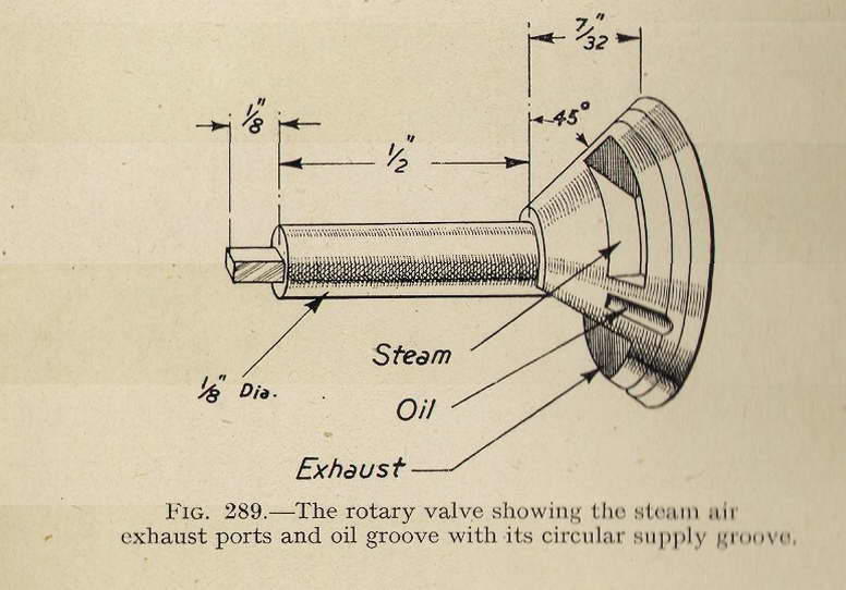
The Valve
As already stated, this is rotary and conical. It is drawn in perspective in Fig 289, and shows clearly the form of both the steam port and the oil port with its circular supply groove. This groove is kept filled with oil by a corresponding groove in the valve face, and this is supplied by a pipe taken in on one side of, the valve chest, and leading from the tank, shown in Fig 285.
The approximate position of the pipe is as indicated, but the point of entry is really immaterial so long as it clears the seatings for the flanges on the steam pipes, between the ports and the cylinders. Neither does it matter on which side of the engine the pipe enters.
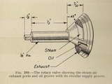 In Fig 289 the steam port is seen as a port passing through the valve. This arrangement is rendered necessary by the oil groove which requires a completely annular outside to the valve.
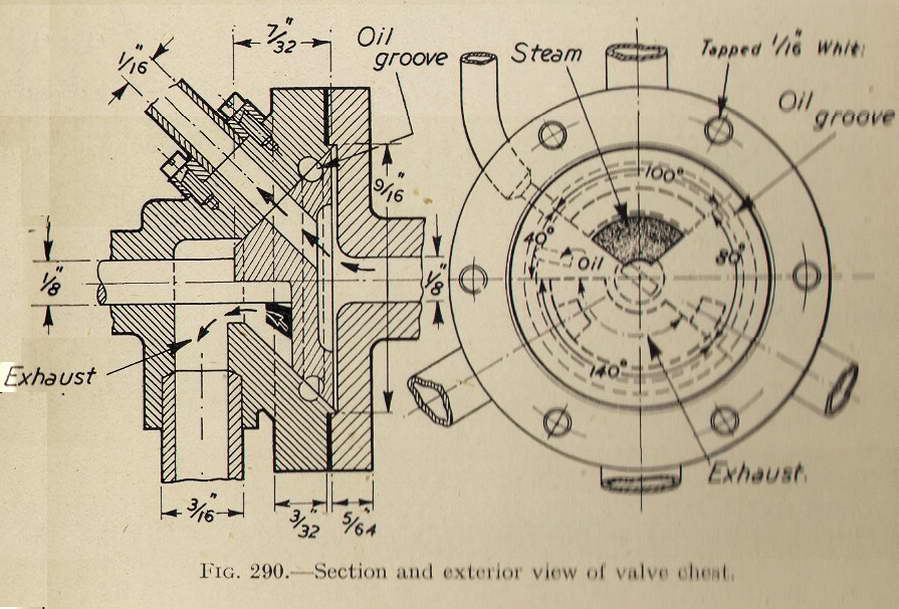
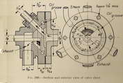 The exhaust cavity and the steam passage, together with the valve faces between them, make the same angle each with the other. These angles are shown in the right-hand drawing of Fig 290. As both the valve proportions and ports to the cylinders are the same as in the compressed air engine the valve events will also be the same.
Metals to be Employed
With regard to the material from which the valve and parts of the engine, other than those already specified, should be made, it is recommended that the valve and its spindle be turned from mild steel, also the valve chest cover to which the steampipe union is attached. The" chest" itself may be of hard gunmetal, whilst the plate work of the crankcase, the crank, crank�shaft and connecting rods are all to be of mild steel. Pipes from the valve chest to the cylinders are of copper with gunmetal flanges silver-soldered on. All screws will, of course, be of steel with either B.A. or Whitworth threads as preferred. The cylinder ends and the main bearing for the crankshaft are of gunmetal silver-soldered in place. The lapping of the cylinders should, of course, be done after the closed ends and the rings are fixed.
The Crank
In building up the crank with its shaft and crank�pin two alternative methods are available. Either the holes in the crank and the turned ends of the shaft and crankpin may be a good driving fit together, further security being obtained by small cross�pins passing through the crank and shaft, and riveted over, or the shaft and crankpin can be a fairly easy fit in the crank and fixed by silver-soldering. A combination of driving fit and silver-solder is not practicable, because one cannot be sure that the solder will flow into the joint, hence the reason for the easy fit if solder is adopted. Between the two methods there is not much to choose, but the writer is inclined to prefer driving and cross-pinning, especially as it is possible to further secure by slightly counter�sinking the holes in the crank and rivet over the ends of the crank�pin and the crankshaft.
The Steam Generator
The boiler or, more correctly, steam generator, consists of two main parts, the shell and the flash coil. The principle on which these are used has been already explained, and it suffices to say that either of these could be used for steam supply to an engine separately, but on the one hand the shell boiler could only deliver steam at its working pressure, and the flash coil could only deliver steam which it had itself generated from water at a low temperature. Now the two, in combination, will have the effect of delivering to the engine steam at a pressure which will certainly be above that of the shell and that at a high degree of superheat, since the water when it enters the coil will already be in a state to be flashed into steam.
The Shell
For the barrel of the shell boiler a 4-3/16 in. length of seamless copper tubing is required, 1-3/8 in. diameter and about h3/64 in. thick; the ends are beaten from sheet copper of the same thickness and silver-soldered into place.
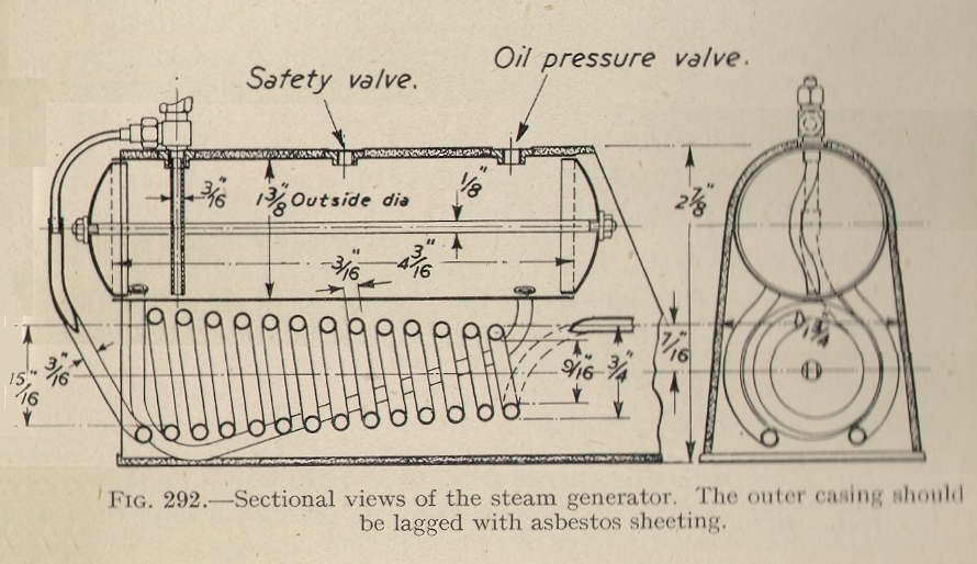
The drawing, Fig 292, shows the whole generator in longitudinal and cross sections; here it will be seen that a longitudinal stay with nuts at each end is taken through the centre of the boiler shell. This stay would be best made of 1/8 in. diameter mild steel, and to prevent rusting it may be tinned from end to end over the threads after they are cut, a good thick coating of the solder being applied. After the stay is in place and the nuts screwed up, both they and the ends of the threads should be well covered with soft solder. Before this stay is put in, the two water-tubes should be bent to shape, fitted by expanding them into the shell and silver-soldered.
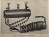
Fig 291—The flash coil and water supply tank.
The Flash Coil
This is to be of 3/16 in. diameter steel tubing of fairly stout gauge; about -h in. or slightly heavier. It should be bent around a tapered mandrel, turned to the correct diameters as figured in the drawing. The action of bending is bound to flatten the tubing slightly unless the mandrel is of cast-iron spirally grooved to a depth nearly equal to the diameter of the tubing. The alternative is to use a wooden mandrel of, say, beech, covered with a layer of asbestos cardboard, but whatever material is used the tubing must be heated, and the best way to do this will be with a gas blow�pipe or paraffin blow-lamp, letting the flame play upon the pipe as bending proceeds. The pipe, at the point of bending, should be brought to a very dull red. Cold bending is liable to result in cracks, whilst if it is of bright red or nearly white heat it will flatten to an excessive amount.
The pipe leading from the bottom of the shell to the wheel valve can be of copper, as also the one to which the union is attached; both of these can be soft-soldered at the valve, but the end of the second pipe must be silver-soldered into the upper end of the steel flash coil.
The union which attaches the flash coil to the engine would be best made of steel, though a Bassett-Lowke brass union will stand up to the temperature and the work it has to do for a considerable time.
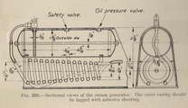
Fig 292—Sectional view of the steam generator.
The outer casing should be lagged with asbestos sheeting.
The Boiler Casing
The form of this, in cross section, is shown in Fig 292. It will be best made of the thinnest sheet metal obtainable, tinned steel is preferred, having a thickness of about No. 30 on the standard wire gauge. It is to be lined very thickly with asbestos card, as shown in the cross-sectional view in Fig 292, which card must be soaked in water to render it pliable, so that it can be shaped to fit the curvature of the plate. The tinned, or iron, plate cannot, for obvious reasons, be soldered at the necessary joints, but must be secured together with either rivets or small brass screws and nuts, the latter being, perhaps, the more convenient, because at some time it will become necessary to remove the boiler for cleaning or repairs.
In order to gain access to the union which couples up the engine to the flash coil, an opening will have to be provided in the casing; this may well be cut at the bottom, directly under the union, and will be fitted in with a cover plate secured with screws.
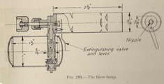
Fig 293—The Blow Lamp.
The Blow-Lamp
The general arrangement drawing, Fig 285, shows that the heat for evaporation of the water is provided by a blow-lamp of the self-vaporizing type. This is shown in section in Fig 293.
The Valve
The valve, screwed as shown, is made from hard�drawn brass rod, filed square at the outer end and fitted with a fluted wooden knob to serve as a handle for revolving and adjusting the valve. The inner end of the rod is turned to a tapered point, having an angle of about 45 degrees.
The Fuel Container
The container for the fuel, which is ordinary petrol, is made from either copper or brass, having a thickness of about 1/32 in. The middle portion is a piece of seamless tubing, whilst the two ends are beaten or spun to shape and soldered in. Before fixing the ends a collar should be silver-soldered into a hole cut to receive it. This collar is screwed to take a plug fitted with a cross bar to serve as a filler cap. The container is then bored to receive a 5/16 in. brass tube, which tube is brazed to the valve and nipple casting. As may be seen from the drawings, the casting is silver�soldered to the container. It differs from that shewn in the photographs, being of a later and improved type.
The mixing and vaporizing tube may also be of either copper or brass. A gap should be cut in it wide enough to give the necessary semi-rotary movement to the extinguishing valve.
The Extinguishing Valve
This valve is a thin steel plate pivoted on a collar screwed into the nipple block. Its shape and action is clearly shown in Fig 294. The central hole of the plate can be of any suitable diameter, say, l/8 in. It is required to be sufficiently large to allow the gas to pass freely from the nipple when the valve is in the open position, and yet not so large that it prevents the nipple being completely closed when the gas is required to be shut off.
 For the initial heating-up of the burners, and to ignite the first gas formed, either a pan will be required to hold a small quantity of methylated spirit or a wire frame, or rack, filled with asbestos wool which can be saturated with methylated spirit.
The latter will doubtless be more convenient, since the spirit cannot be spilled. Such a rack can be formed of stout brass wire silver�soldered together and either made to hang by a loop from the nipple block, or be silver-soldered to the barrel of the container. The flame from the pan or asbestos wick must be arranged to play around the whole of the part containing the nipple and the inner end of the mixing tube.
For the initial heating-up of the burners, and to ignite the first gas formed, either a pan will be required to hold a small quantity of methylated spirit or a wire frame, or rack, filled with asbestos wool which can be saturated with methylated spirit.
The latter will doubtless be more convenient, since the spirit cannot be spilled. Such a rack can be formed of stout brass wire silver�soldered together and either made to hang by a loop from the nipple block, or be silver-soldered to the barrel of the container. The flame from the pan or asbestos wick must be arranged to play around the whole of the part containing the nipple and the inner end of the mixing tube.
To complete the lamp ready for use the tube leading up to the needle valve must be lightly packed with loose cotton or asbestos wick, the lower ends of this being spread out, as shown in Fig 293.
Automatic Extinguishing
The apparatus for automatically shutting off the flame is shown in detail in the sectional illustration in Fig 294.
 This method of packing-if packing it can be called-was adopted in the Williams and Robinson vertical tandem compound engines where, the cylinders being all in line, the piston rods passed from one cylinder into the next, without any stuffing boxes and glands, and simply had such. grooves turned in the piston rods. The theory is that such small quantities of steam which may pass have to fill the first groove, then be, " wire-drawn" and fill the next, then wire-drawn into the third, and so on. By the time the last groove is reached, the piston stroke is completed and so the steam loss is infinitesimal.
 In Fig 289 the steam port is seen as a port passing through the valve. This arrangement is rendered necessary by the oil groove which requires a completely annular outside to the valve.
 The exhaust cavity and the steam passage, together with the valve faces between them, make the same angle each with the other. These angles are shown in the right-hand drawing of Fig 290. As both the valve proportions and ports to the cylinders are the same as in the compressed air engine the valve events will also be the same.

 For the initial heating-up of the burners, and to ignite the first gas formed, either a pan will be required to hold a small quantity of methylated spirit or a wire frame, or rack, filled with asbestos wool which can be saturated with methylated spirit.
The latter will doubtless be more convenient, since the spirit cannot be spilled. Such a rack can be formed of stout brass wire silver�soldered together and either made to hang by a loop from the nipple block, or be silver-soldered to the barrel of the container. The flame from the pan or asbestos wick must be arranged to play around the whole of the part containing the nipple and the inner end of the mixing tube.
For the initial heating-up of the burners, and to ignite the first gas formed, either a pan will be required to hold a small quantity of methylated spirit or a wire frame, or rack, filled with asbestos wool which can be saturated with methylated spirit.
The latter will doubtless be more convenient, since the spirit cannot be spilled. Such a rack can be formed of stout brass wire silver�soldered together and either made to hang by a loop from the nipple block, or be silver-soldered to the barrel of the container. The flame from the pan or asbestos wick must be arranged to play around the whole of the part containing the nipple and the inner end of the mixing tube.
 The apparatus for automatically shutting off the flame is shown in detail in the sectional illustration in Fig 294.