| WORKSHOP HINTS AND TIPS |
|
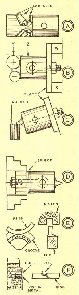
Machining a Small Piston (2)By GEOMETERWITH the inside finished above the gudgeon pin bosses, and the bosses bored with a tool and D-bit, the machined-from-the solid piston was at the stage when only three minor operations remained before work could be started on the outside. The operations were to ream the bosses, to bore the skirt up to them, and to face the bottom of the piston to length from the gudgeon pin centres. I did the reaming by hand, holding the reamer in the bench vice and twisting the piston on it. Both had been heated in water to expand the alloy for the steel gudgeon pin to be a good working fit at running temperature. First, I started the piston a little way on the reamer, which had been oiled. Then I heated both in a can on a stove. Using rag because the piston was too hot to hold in the bare hand, I got the reamer through its bosses with one withdrawal to clear swarf and one reheating to expand the alloy. For the remaining two of the three minor operations I made a set-up in the independent chuck with the fulI length of the piston, including the deflector, projecting from the jaws. I set inside callipers to the micrometer and tried them in the skirt as it was bored; and to obtain the length of the skirt in facing, I used a depth gauge to measure from the end to a smooth.fitting rod in the bosses. The first outside operation on the piston was to turn the piece for the deflector with the topslide at an angle, as the deflector tapers a few degrees from the crown where it comfortably clears the cylinder. This was work for a parting tool, and on its completion I had left the piston about 0.010 in. overIength. Now came the major operations of roughing and then machining the deflector from the round stub on the top of the piston. First I sprayed the stub with quick-drying paint to show scriber marks as the deflector was roughly outlined with the piston in the V-block and on the surface plate. Then I hacksawed surplus metal from the stub, as at A, holding the piston by its chucking piece in the vice. Next I cleaned off the roughnesses with a coarse round file. Lastly, I used the hacksaw again to separate piston from chucking piece. As can be seen at diagram B, the deflector is formed by two different radii, which it is obvious can be machined with a fly-cutter. The work was done with a stiff boring tool mounted in the four-jaw independent chuck so that its cutting tip could be set to the required circles. To check a circle, a piece of metal on the topslide was brought to the tip, and then the tool was turned 180 deg. and a depth gauge was used from the tip to the metal. The piston was mounted on a flat plate with an eyebolt and the plate was clamped to the vertical slide with packing W and X. I could get the slide far enough back for this mounting—otherwise I should have used an angle plate on the slide and set the face of this 3cross the bed. I brought the gudgeon pin bosses horizontal, testing on the ends of the rod for the eyebolt. To locate the tool and the piston, I measured from the cutting tip to the plate. Then I made a check with the surface gauge to the top of the swept circle Y, and, after adjustment, to the top of the piston Z. After machining the two radii, I turned the piston 90 deg. and moved the vertical slide round for chamfering operations with an end mill, as at C. To set up the piston for turning to size, I used a stub mandrel with a spigot, as at D. I turned the surplus length from the piston, took a cut along it, and machined the groove, as at E, so that the ring would roll beneath the surface. On finishing cuts, clearances (1-1/4 in. dia.) were 0.0055 in. at the crown, 0.004 in. at the gudgeon pin, and 0.003 in. at the skirt. To peg the ring, I drilled and tapped a hole for a small brass stud, with piston metal wedged in the groove, and carefully filed the gap of the ring, as at F. |
|
|
Back to Geometer Index Page.