| WORKSHOP HINTS AND TIPS |
|
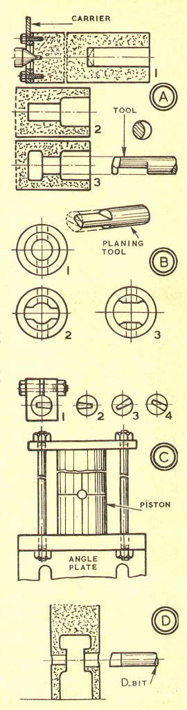
Machining a Small Piston (1)By GEOMETERAFTER boring the cylinder of my small two-stroke engine, as described in the previous article, I finished it by lapping and was ready to begin work on the new piston. I had no casting for this, and no core box for the inside of a casting, and so I decided to make the piston from solid. If there had been a core box to hand, I could have turned a piston pattern very quickly in wood. Then a casting could have been made which would have needed only the minimum of inside machining. As it happened, my decision to machine the piston from solid was helped by the presence of a piece of piston alloy (light alloy) in a box of off-cuts. It was about t in. oversize on the diameter and some It in. longer than the piston, including the deflector. As it was of cast metal, the surface was rough; and as the piece would have to be chucked firmly and truly, my first job was to machine it all over. With the material in the chuck, the ends were faced and centred. Then a set-up was made between centres for the outside to be turned parallel—well oversize, of course. The outside diameter would not go into a normal carrier, and I used a piece of flat steel as a substitute. It was drilled with a large hole to clear the spindle centre and with two small ones for setscrews into the end of the material, as A1 (left). To begin work on the inside of the piston, the parallel material was chucked with enough projecting for a line to be scribed round the outside at gudgeon pin centres. First, I drilled to the crown with a drill that left light facing cuts in the gudgeon pin bosses. Then I flattened the drill, backed off its lips, and squared out the hole, as at A1 (right). Next I bored out the hole to the underside of the gudgeon pin bosses, as at A2, but to the diameter of the inside above the bosses, where extra metal had to be left for the piston ring. My object was for the skirt diameter to serve as a guide in the planing operations which followed the boring. To bore above the bosses, as at A3, I had made a tool in round silver steel, as shown. It would just go into the drilled hole. I had offset the silver steel rod in the chuck and had turned the shank to the section illustrated. Then I had finished the tool to shape by filing. Finally, it had been hardened and tempered. . A mounting was made in a clamped holder on the vertical slide to help in setting the tool to height. In the course of working, I had to draw it from the piston several times to clear swarf from the restricted space above the bosses. At this stage the inside of the piston appeared as at Bl, with the bosses in a ring of metal. To plane away the surplus, a planing tool was made from the same rod as the boring tool, to use in the same holder. A flat tongue was filed on the end, as shown, and then backed off, narrowed and given clearance for easy working. This tool, like the other, was tempered to dark straw. The piston was fixed by engaging back gear to the spindle. Then the ring of metal was slotted to the shape of B2, with two settings of the planing tool. At the first, the tool was towards me, as at C1. At the second setting, it was away, as at C2. Then I turned it back again, and reclamped it first with an upward inclination, C3, and then with a downward inclination, C4. For cutting, feed was given by the cross slide and vertical slide, and cuts were carried through with the saddle. Operations were repeated with the tool away from me, so that the final shape in the piston was as B3. With a scribing block, the piston was marked on the sides and end. It was then turned 90 deg. to a square for marking gudgeon pin centres. These marks located the piston on the angle plate, where it was clamped, as at C. Bosses were drilled. The outer one was bored and the inner finished with D-bit, as at D, for final reaming. |
|
|
Back to Geometer Index Page.