| WORKSHOP HINTS AND TIPS |
|
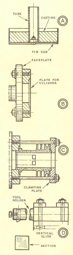
Reboring a CylinderBy GEOMETERWHEN my small two-stroke engine became increasingly hard to start, and the exhaust note lost its crackle, I decided that something must be done to rectify loss of compression. The engine had done a lot of running. I suspected the worst about it, and as I was busy I kept putting the job off. Several times I obtained a start at the first pull of the cord after injecting a few drops of oil on the piston. But the time came when I tried this old dodge repeatedly without success. Inspection showed that the piston and rings were worn, so that both would have to be replaced-as I had suspected. The cylinder was bright with a vertical alignment to its polish. It had a slight ridge near the top. Obviously all that it needed was careful lapping. Nevertheless, as a new piston was needed, I decided that I would rebore the cylinder. The extra capacity would be useful, I thought; and the cylinder was thick enough everywhere to stand an increase in diameter, even in the spigot, which—as usually happens—was the thinnest part. The reboring was done by mounting the cylinder on the faceplate and using a boring tool of maximum size. I made this tool first, though I shall describe it last. A really stiff tool was necessary to avoid spring and chatter as the ports passed the cutting edge; and I was not certain that an ordinary boring tool would prove sufficiently rigid. Two circular plates of substantial diameter were used to mount the cylinder, one on the faceplate to locate the cylinder by its spigot, and the other to clamp it from the cylinder head face through long studs and nuts. The cylinder was thus in compression, and could not vibrate in itself, as might have occurred had the mounting been made by clamping on the cylinder base flange. As I had nothing suitable for these plates, I cast them in light alloy from old car pistons. A pair of moulds were used, each as shown at A. Two large tin cans were cut down, centred at the bottom with dividers, and drilled. Then each was fitted with a tube, located on a collar held by a screw and nut. I tapered the outsides of the tubes downwards so that they could be tapped easily out of the castings. To help further in extracting the castings, I coated each tube and the tin can with blacklead. But at the finish the tin cans had to be tom off the castings with pliers. The pistons were broken with a hammer on an anvil, and melted in a ladle with the aid of a large blowlamp and a gas torch. They had been heated and scraped to remove carbon; but the molten metal was stirred and skimmed before pouring. I machined each of the plates in the four-jaw independent chuck. Two circles were marked on one, after it had been faced and rough bored. Then each circle was quartered, and the marked positions were drilled No. 7 and tapped 1/4 in. BSF. Four short studs on one side of this plate held it to the faceplate, as at B; and four long ones on the other side held the cylinder in conjunction with the clamping plate, as at C. The bore for the cylinder spigot and the recess for its flange were machined with the plate finally mounted on the faceplate. The other plate was machined completely in the four-jaw chuck and drilled with four clearance holes for the studs, which were made from mild steel rod. The boring tool holder was machined from square bar, as at D. As the holder would not have entered the cylinder if mounted on the topslide, I clamped it to the vertical slide. There I could easily adjust it for height. Then the slide was fixed by its adjusting screws. I marked the end of the square material for the holder on the surface plate, drilled it up, and supported this end by the tailstock for turning. A cross hole was drilled for a 5/16 in. bit, and the end hole drilled and tapped for a 1/4 in. BSF screw. In reboring the cylinder, an initial deep cut, taken at slow speed, was followed by several light cuts at medium-fast r.p.m. |
|
|
Back to Geometer Index Page.