| WORKSHOP HINTS AND TIPS |
|
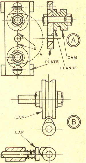
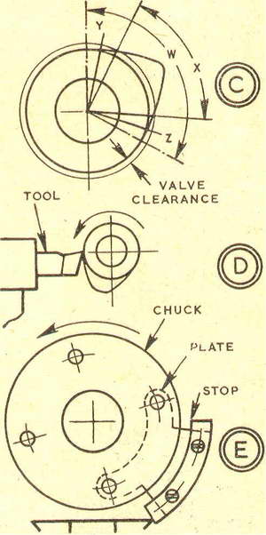
Machining and finishing CAMSBy GEOMETERFOR valve operation in a small i.c. engine, the most practical alternative to the flat-sided tangential cam is the type whose flanks are formed by radii. The flanks of such a cam can be machined in the lathe, by mounting the blank to /sweep on a circle of appropriate diameter. At one setting of the blank one flank of the cam can be accurately turned. Following this, the blank is rotated on its own axis through the opening angle of the cam, then the other flank is similarly machined. Finally, material between the flanks is removed down to the base circle, and a radius (or radii) provided where the flanks converge at the crest. If two separate cams are required, even with different opening angles, the flanks of both can be machined together, with a consequent saving in time. The principle of the setting is as at A, which shows two blanks on a plate which can be mounted by screws to the faceplate or held in the fourjaw independent chuck. Each blank carries a flange, which is marked with reference lines for the opening angle of the cam - and can be turned off when the flanks are finished. The reference lines are set to the centre line, U, on the plate, and the blanks held firmly by well-fitting studs and nuts. Circle V provides the radius for the flanks, so that measurement can be made with calipers or micrometer. If only one blank is turned at a time, it can be prepared by necking down to base circle diameter, which will indicate how far to take down each flank. For a set-up as at A, the plate can have three holes on its centre line, the middle one for a plug to set the plate true, and the outer two on the pitch circle for mounting the cam blanks. Radius of the pitch circle is that of the cam flanks, minus base circle radius, and hole centres can be located by careful marking out, or using tool-maker's buttons. Preferably the holes should be bored or reamed to take silver steel studs threaded for nuts. Marks on the flange of a cam blank giving opening angle can be provided as follows. A fairly large disc of cardboard should be cut to a circle, and the opening angle made in sharp pencil lines, then a centre hole punched. The disc may be mounted on the blank on the stock, using a plug and adhesive, and the opening angle marks brought to ascribing block pointer, so that a V-tool sideways on the slide can be used to nick the flange. Base circles can be rough machined by setting the cam blanks round a little at a time on their studs; and for finishing, they can be turned, or filed with the cam between washers. Crest radii can be filed to radius gauges, then lapped as at B. For a large radius, a form lap can be run in the chuck, and the cam moved past it on a plate on the vertical slide. For a small radius, a spring-loaded flat lap can be used, in a holder on the slide rest driven by a flexible shaft, with the cam on a mandrel in the chuck and this oscillated by hand. ClearanceA point not to overlook with a cam is the effect of valve clearance, as at C. On a cam 1 in. dia. with 0.003 in. valve clearance, the difference between angles W and X amounts to about 16 deg. (32 deg. on the crankshaft). However, owing to the shape of the cam and the tappet foot, the actual opening angle would be approximately between points Y and Z, with the difference some 8 deg. (16 deg. on the crankshaft). To counteract this effect, either the base circle can be undercut and the lift blended in, or the opening angle (and lift) can be increased by the requisite amount. Turning or undercutting a base circle can be done as at D, with the cam on a mandrel in the chuck, which can be pulled round by hand. The tool is on the slide, and the cam is turned back before the tool is advanced on the bed. A stop is useful in this work, and can be arranged as at E, attached to a plate on the chuck backplate, to come round, back to front of the lathe bed. |
|
|
Back to Geometer Index Page.