| WORKSHOP HINTS AND TIPS |
|
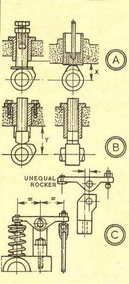
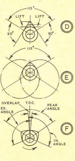
Cams and valve gearBy GEOMETERIn the four-stroke engine, a field for development may often be provided by the cams and valve operating gear, which exert a direct influence on .. breathing" in the engine, and on the evacuation of exhaust gases-an influence arriving through the lift of the valves, their opening periods, and the relationship of these to piston movements. All these can be varied easily even with the common flat-sided tangential cam. In fact, alteration of one feature can automatically change another, and call for further adjustment. This is so if the opening angle of a cam without dwell is widened, when lift is also increased, so dwell must be given, or the crest radius increased. On the other hand, increasing the lift of such a cam from the same opening angle, the crest radius must be smaller (which is not possible if it is already the minimum), or the whole cam must be larger. Two types of camThe flat-sided cam is one of two types straightforward to produce. It can be filed. The other is the cam whose flanks are radii which can be turned or ground in the lathe. Either cam will work with a tappet or rocker, though a flat-bottomed tappet may call for a change from one type of cam to the other. As at A, right, a flat-bottomed tappet is across the flank of a flat-sided cam at the point of opening, and at the limit to increase lift would cause severe side thrust. But if the cam is changed to one with curved flanks, initial lift is given to the tappet before the cam peak contacts the foot. Incidentally, a simplification of such a tappet for operating a push rod is as at right-with drilled lubrication holes. Alternatively, with a flat-sided cam, a tappet with a rounded foot can be used, but then it must be restrained from rotation. If this is done, as at B, with a fork at the bottom of the guide, distance without support is increased-comparing X with Y. To avoid wear which can increase through reduced tappet support, extra lift may be obtained at times with the same cams and tappets through overhead rockers of unequal arm lengths, as at C. Preferably such rockers should be in light-alloy to keep down the" polar moment of inertia," and fitted with steel tips and adjusting screws. Oversize drawing helpsTo study what may be advisable, cams can be drawn to scale several times oversize-and the proportions then adjusted as required. First, the opening angle of half the crankshaft angle is needed to set out on the cam base circle. For an inlet valve opening 5 deg. early, closing 45 deg. late (an example only), the crankshaft angle is 230 deg., and the cam angle 115 deg., as at D and E. For a flat-sided tangential cam, D, the flanks make angles of 90 deg. to radial lines at the opening angle. They can be blended into a small radius at peak lift; or reducing lift by an arc, "dwell" can be given. This would be done with a cam having a wide opening angle, which would otherwise give a very high lift. For a cam with curved flanks, E, the angle of opening can be set out the same, and the lines continued back through the centre of the cam. Experimenting with different radii, centres can be found on these lines to set out "generating circles" of suitable size which are blended by a small radius at peak lift. With the proportions of both inlet and exhaust cams decided, a composite diagram can be made, as at F, showing opening angles, overlaps at t.d.c., and the angle through the peaks. Particularly, then, if cams are to be produced integrally in pairs will it help to avoid mistakes in setting out. |
|
|
Back to Geometer Index Page.