Model Engine Gallery Page 4
Click on the images to view them larger size.

|
These pictures were received from brothers Ron and Bob Lane (England).
They hit just about all my hot buttons, so I asked the Lanes to
write a few words about themselves and their engines to accompany
the photos:
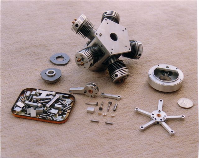
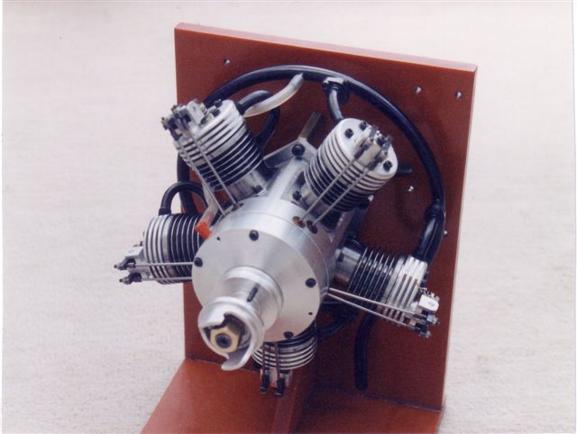
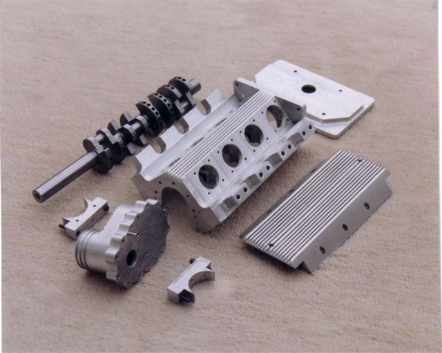
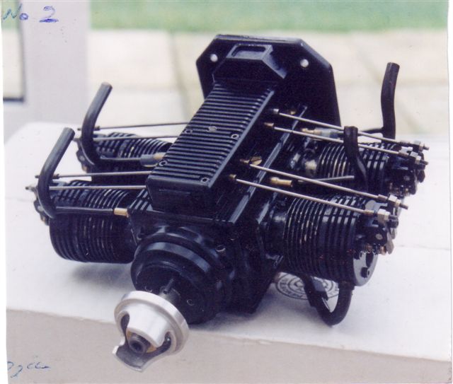
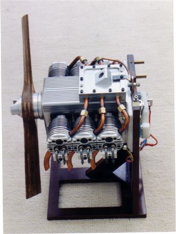
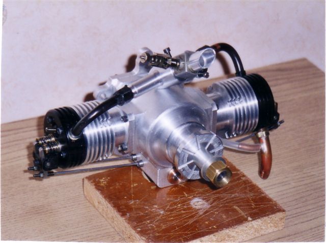
We are both retired (I am 68, Ron is 67) Cockneys from the East End of London, we went through the Blitz sitting under the kitchen table, were bombed out twice but survived. We were told that a distant relative Richard Lane, a bricklayer worked for Isambard K Brunel on the first Thames tunnel in the 1800s, this is also mentioned in the book "The First Thames Tunnel". Grand Father on Dads side was a lift engineer and made model live steam locos on a foot treadle lathe under gas light and won a prize at a model engineering show pre-war, this engine was lost in the war. Our dad, also a lift engineer, made two steam locos, a freelance 2.5" gauge, and a 5" Evening Star (the last British Rail Steam Loco made), three reflector telescopes: a 9" and two 12" diam. grinding the mirrors himself. He also made two televisions, in the 1950s, and a three wheel car similar to a Reliant Robin with a V twin Jap engine. A very clever dad, we learnt a lot from being brought up in a workshop, so you can imagine how we got the disease. Mum was not pleased. Ron was an apprentice tool maker and worked for the Mullard Radio Valve firm now Thorne EMI. I was a lift engineer and fitted lifts in places from restaurants dumb waiters, to mines and ships. We started Aeromodeling in 1947 when an uncle who was in the Royal Flying Corps as a Rigger gave us a rubber powered plane that we crashed, Then Dad bought us an ED Bee for Xmas. It cost �2.7.6p old money. We went through gliders, rubber and power free flight, control line, very early home made Radio Control, single channel, Galloping Ghost, then reeds, and then propo since the early 70s. Buts that's enough about us. Ron is the lathe expert and did all the machining. We both assembled and tested the engines. I made a wood mock up of the Radial to get the idea how they worked. Even with Richard Green's drawings its not easy. He made fixtures to get all the parts the same and for speed. The crank cases and shafts are all one offs, except the two for the two Radials made. Making the crankshafts and camshafts was very tricky. Fitting the pistons and rings to get good compression was tricky, and the type of glow plugs makes a difference to the performance. The radials both started by hand and on slow speed / tickover the blades can be seen quite clearly. When the first radial was flown an alloy conrod broke. Luckily not much damage occurred, so fluted steel rods were fitted. It needed a lot of oil to prevent seizing. The bottom cylinder plugs tend to oil up so I used an on board glow supply on low speed. We noticed that the compression improved with running on all the engines. The Boxer twin has wet liners in alloy fins and will be used in an autogyro, It's 16cc capacity. All those parts for the V8 glow engine were machined from solid. All the barrels, heads, valves, rockers, and pistons on all these engines are 8cc swept volume. The V8 has a reduction gear to drive a 24" three blade home made prop. This engine would run without a prop. It was used in a 5th scale Hawker Hurricane MK 1 but due to a collapsed under cart the plane met its end—luckily the engine was undamaged. The 5 clyinder radial is 40cc and has flown in a Eindecker type model;
a Richard Green design.
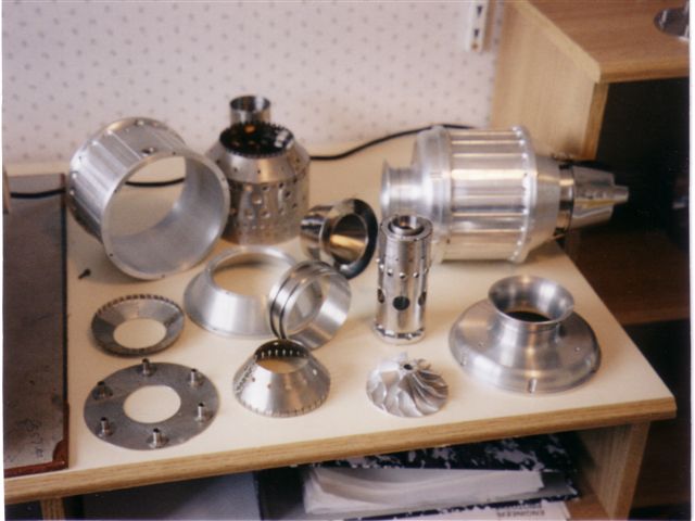
The Gas Turbine, the HD4 was designed by Harold Denver.
Best Wishes Bob & Ron Lane. |
|
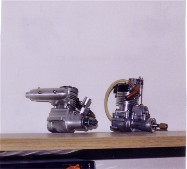
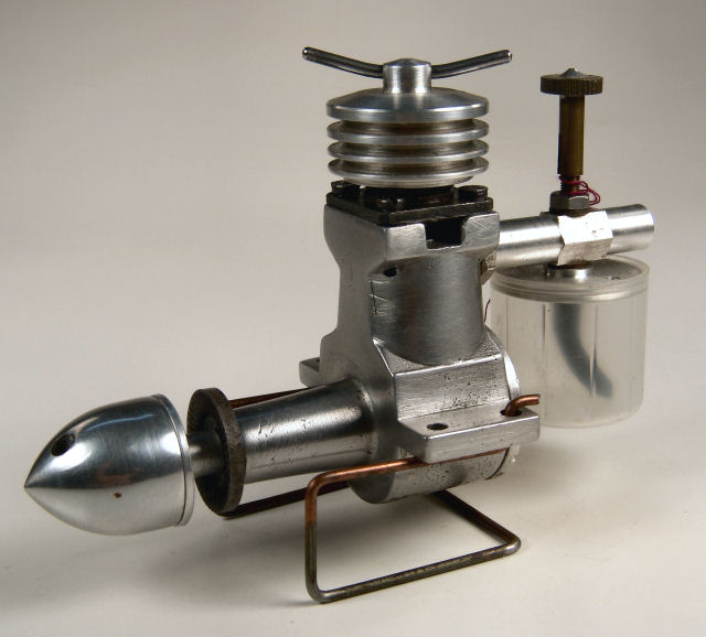
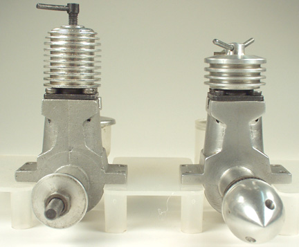
Here is the "Bulldog Mills", and as far as we know, it's the only one
of the breed. It was modified from what is
affectionately known as a "Curry Mills" (Aurora, India) by Motor Boy
Bert Streigler of Texas. A picture of the engine has been in the
Engine Finder for a long time,
but while researching the
Mills 1.3 Mk I, I asked Bert
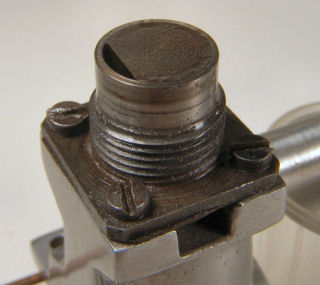
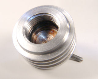
for some more info on the "Bulldog" conversion, in particular, how he
sealed the cylinder. What he supplied is just too good to loose:
There is a high temperature Viton O-ring inside the head. The cylinder was cut off so that it was even with the top of the piston when the piston was at TDC. Then, some of the threaded part was machined away to allow the O-ring to seal on the cylinder—hopefully, you can see the O-ring inside the contra in the attached pics. The whole mess yields an engine that is only 3/8" from the top of the cylinder head to the top of the cylinder flange, compared to 1.0" for a regular Mills 1.3. One immediate advantage is that the engine reaches running temperature almost immediately and does not lose the customary 100-150 RPM that Mills usually lose upon reaching running temperature. I believe the mass of metal above the combustion chamber keeps the top of the cylinder too cool, while the piston gets much hotter which results in a tighter engine. This Bulldog version really goes and has proven to be viceless. I ran it at Old Warden some years ago, but no one seemed very interested in it. In my opinion, it is an improvement over the usual contra set up, but what killed the interest is that it is not traditional! Bert |
|
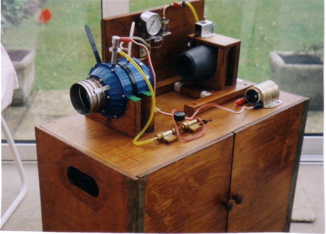
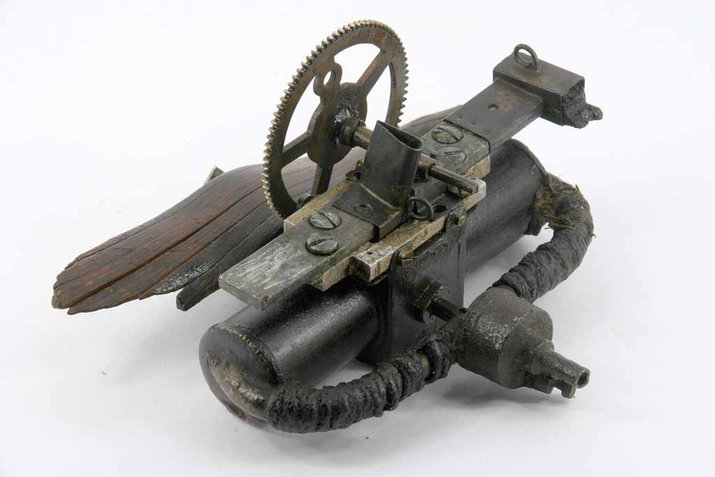
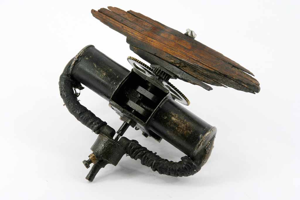
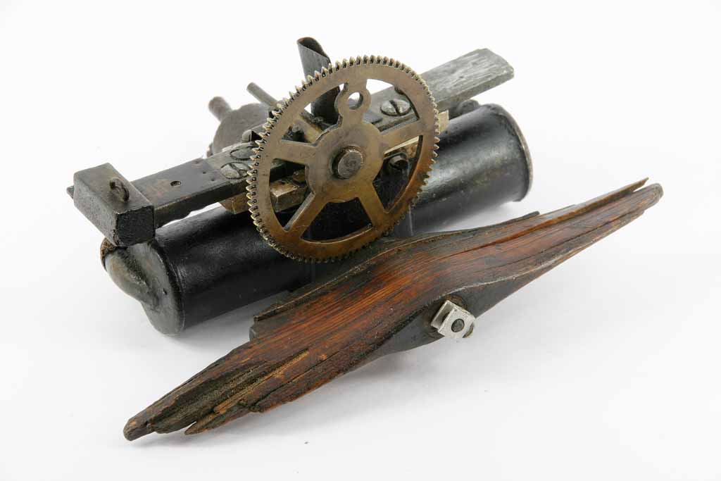
The Model Engineer magazine has been in continuous publication
for over 100 years. For a goodly part of that time, it was the only
magazine catering to model making, so published articles on aircraft,
boats, cars, electronics—in fact everything,
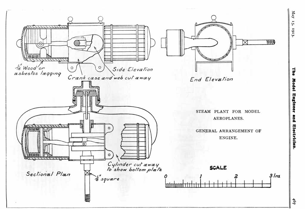
including a do-it-yourself refrigerator! In 1913, the magazine (then
called the Model Engineer and Amateur Electrician) published a series
of articles by HH Groves
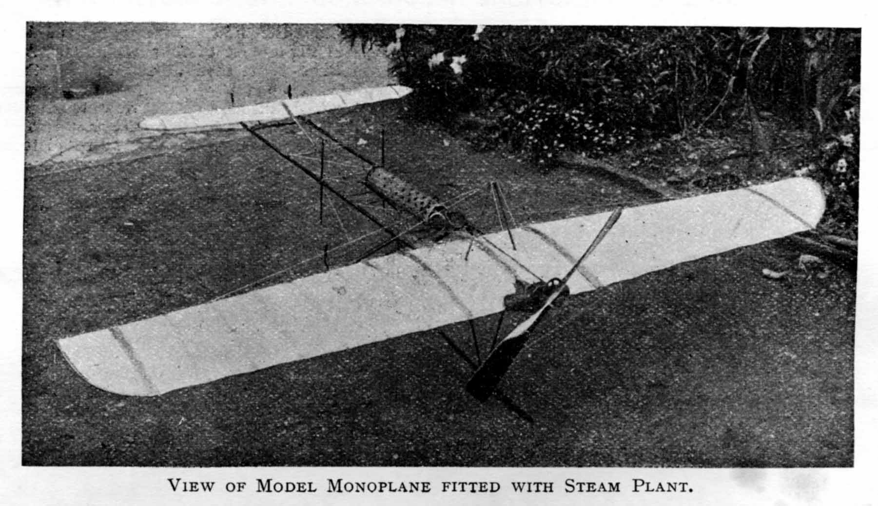
on building a flash steam powered model airplane.
This series has been reprinted in booklet form by Lindsay Publications
(USA), and more recently by TEE publications (England).
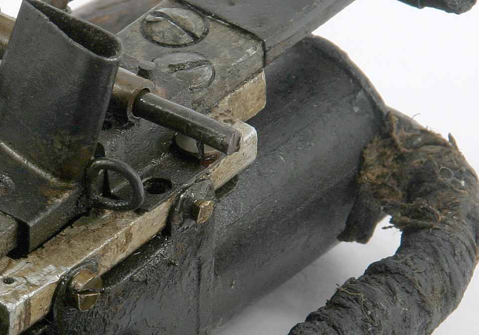
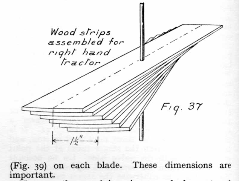
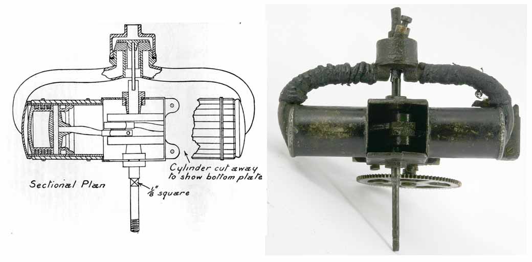
A while back, Motor Boy Ken Croft was involved with the restoration of a HH Groves model that utilized a reduction gear drive from a small IC motor to a large props in a "Wakefield Streamline" like model. This was done in conjunction with his friend Mike Beach who had been given charge of the relics (and others) for restoration and preservation. The story of the Groves Wakefield and attempts to make it fly appears in the SAM 35 Yearbook #12. Recently, Mike and Ken discovered what we believe to be the genuine original HH Groves steam engine that was detailed in the ME 91 years ago. I'll let Ken relate the tale: Some time ago Mike Beach and myself got involved in the restoration and flying of a mdel built by H H Groves, the very early pioneer of powered model flight among other things. When we saw that Tee Publishing have a booklet dated 1913, by the same HH Groves, entitled "A Steam Plant for Model Airplanes", I ordered a copy immediately. The booklet turned out to be reprints from the Model Engineer of 1913. It gives details of the development of the steam plant, and to a lesser extent, of the model aircraft it powered. Mike has for some time had in his collection, a steam engine believed to by Groves, but without provenance. The interesting thing is that Mike's engine in every respect is the same as the one detailed in the 1913 reprint. So much so that we believe Mike's engine is the actual one from 1913 that is the subject of the article. In detail, Groves quotes a 4:1 ratio for the boiler feed pump driven by a gear from the front of the crank shaft, Mike's has gears of 84 and 21 teeth. The drive to the steam chest is via a slotted coupling, the steam chest details are the same and the appearance and layout is the same. Groves gives details of how to laminate the prop, and the laminations are there to see on what is left of the prop. We believe we have here an actual piece of history from 1913, the actual engine built by Groves. On the close up of one of the cylinders, you can clearly see the lines where the strips of wooden lagging have been on the outside of the cylinder. The streamlined strut socket is part of the mounting of the engine to the airframe. There are so many features that are absolutely identical to the engine described by Groves, that it was either his actual engine, or a copy made from his drawings. The geared drive to the feed pump is shown exactly as on Mike's engine in one of the illustrations in the article. The gears driving the pump are clearly from a clock, as was the case whenever early engineers needed gears! We believe it is the actual engine. |