Feeney Construction Log Page 9:
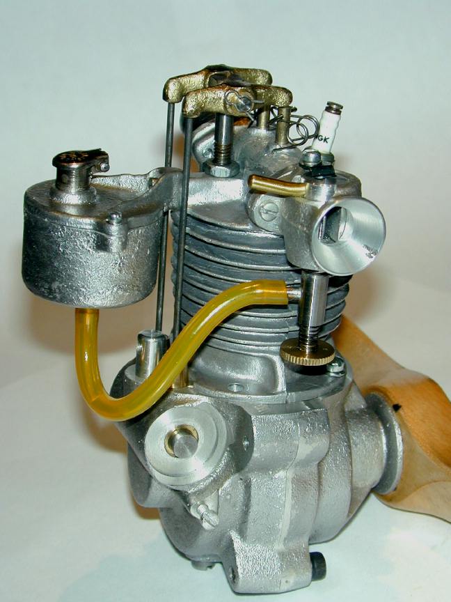
Fuel and Ignition Systems.
![]()
All the major machining is complete now and all we have left to do is the little, fidly things that seem to take as long to complete as the rest of the engine. These are:
Seems that just about every operation on this page was accomplished with mutterings to self about wishing I'd measured that better, or though about that longer and in conjunction with this over here... Guess some people (me) just never learn.
Crankcase Breather
Two-strokes get to vent their built-up crankcase pressure (primary compression) indirectly via the exhaust on every transfer cycle. Four-strokes need to get rid of it (and any corrosive gases that build up in the case) some other way. On the Feeney, this is not a very sophisticated device—no non-return, ball-check valve, no nothing except a little screw-in post that opens the case to atmospheric pressure, hopefully far enough away from the major oil-mist to prevent excessive loss of same.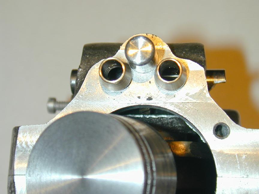 I had a certain sense of unease when I drilled the case, per the plans, for the tappet guides and crankcase breather, thinking "my, they are awfully close together.." I wish now that I'd followed my instinct and moved the breather hole back 30 thou, or so. The plans call for a 1/4-28 tapped hole, which I was now stuck with. Into this, threads the breather post, but there's almost no room, given its proximity to the tappet guides, for a sholder on the breather—that is, the OD of the breather tube itself needs to be 1/4".
The to can then be mounted to an angle plate and aligned to drill the #32 hole for the mounting screw. The rounded lug will seat in the slot machined in the head to prevent the tank from twisting. There's not much meat here, but don't forget that there must be enough clearence on the exit side of this hole for the screw head. The other problem with the design is that after the gitt's cap is in place, screwdriver access to the mounting screw is completely obscured! I now think a better plan is to drill and tap the top for a neat little screw-in filler cap.
That completes the machining of the Feeney. All that remains is gaskets, final assembly, a mounting frame, and the we can see if it runs. At this point, I give it a 50-50 chance.
Back to Feeney Journal front page 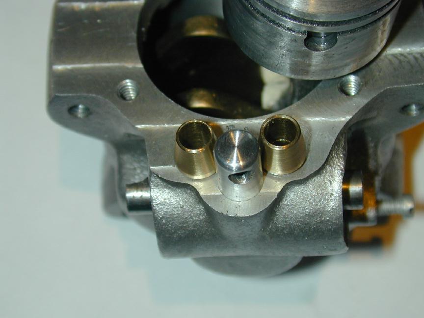 I managed to finesse it with a post of about 0.260" diameter and a narrow "run-out" grove at the top of the (very short) threaded section. Moving the breather back would still allow it to break into the cam cavity to vent the case, but give more room for a greater diameter, and a bit more threaded length. If I was doing it again, I'd tap 1/4-32, or 40 even. Anyway, it's done, with only one scrapped attempt. The actual breather hole was drilled after the post could be screwed in to establish the aft-pointing position, less a few degrees to allow fot tightening it up via a tommy bar in the breather hole when finished.
Fuel Tank
The Feeney fuel tank appears small in comparison to the engine itself, but this is a four-stroke petrol engine and so can be expected to be rather economical, and given its era, would most likely have powered a giant free-flight model (though I seriously doubt many, if any did).
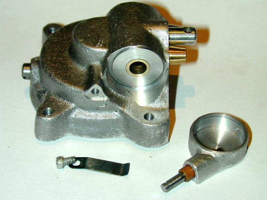
 The design calls for a gravity feed, so the tank hangs off the cylinder head, quite high up. It comprises two castings: the top, which includes the mounting lug, and the tank bowl.
The tank top is a thin, rather delicate casting. It needs two holes to clear 2-56 screws that attach it to the bowl, a hole to clear the 4-40 screw that attaches it to the cylinder, and a hole for the Gitt's style filler cap (not supplied) that adds to the period charm.
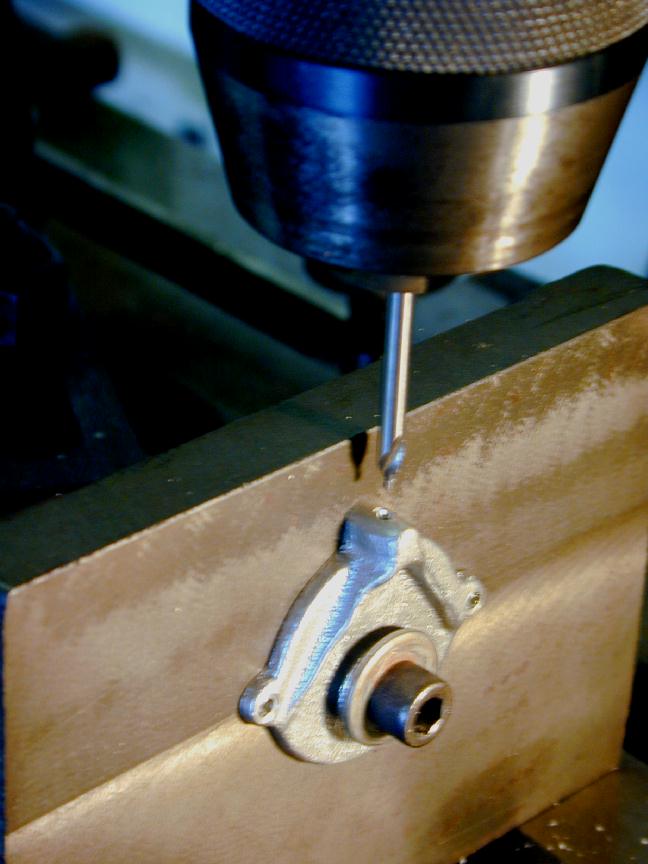
Since the bottom of the casting was reasonably flat, I gave it a quick lick with a file, then clamped it down to drill the vertical holes. The scriber block was used, with pins extended and indexed against the mill table, to central ize the position of the 2-56 holes in the ears. This allowed them to be drilled a precise distance apart by indexing the table in one direction only.
The design calls for a gravity feed, so the tank hangs off the cylinder head, quite high up. It comprises two castings: the top, which includes the mounting lug, and the tank bowl.
The tank top is a thin, rather delicate casting. It needs two holes to clear 2-56 screws that attach it to the bowl, a hole to clear the 4-40 screw that attaches it to the cylinder, and a hole for the Gitt's style filler cap (not supplied) that adds to the period charm.
Since the bottom of the casting was reasonably flat, I gave it a quick lick with a file, then clamped it down to drill the vertical holes. The scriber block was used, with pins extended and indexed against the mill table, to central ize the position of the 2-56 holes in the ears. This allowed them to be drilled a precise distance apart by indexing the table in one direction only.
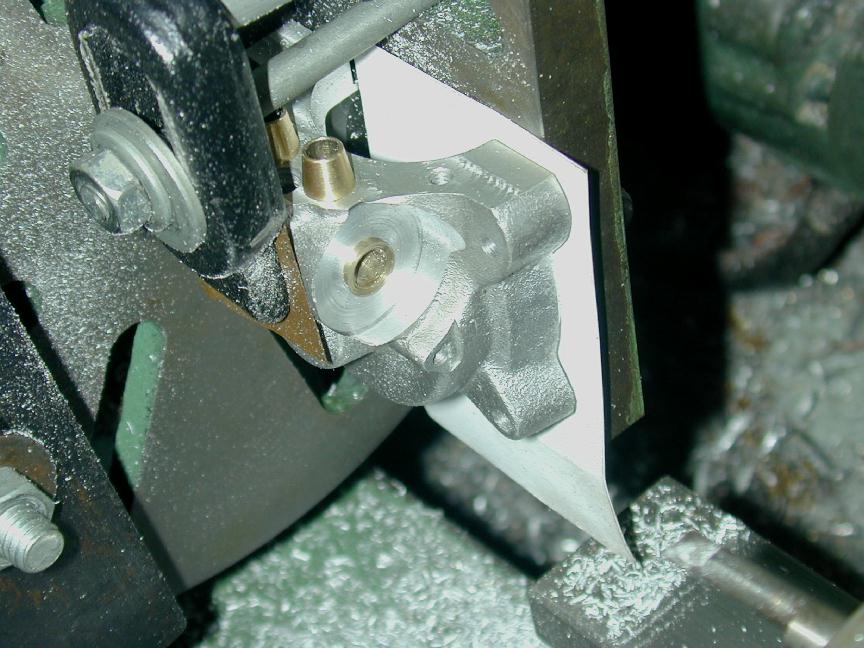
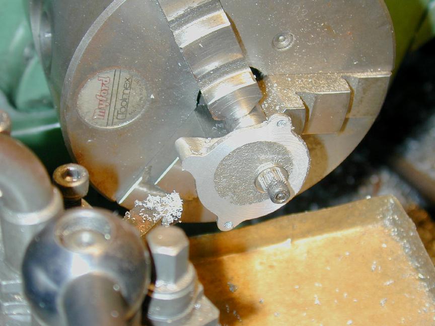 The filler hole was then used to jig up the top to machine the lower face which needs to seal against the tank bowl. In the photo, it has been mounted offset so the light skim is concentric with the top, not the offset filler hole. Staring now at the photo, I'm totally at a loss to understand how this was accomplished, but it obviously was. I'd have thought packing under one of the chuck jaws, but I can't see any. Also visible in this shot is the round profile filed onto the mounting post at the 9 o'clock position that will key into the matching 3/32" radius concave depression on the cylinder head.
 The tank bowl machining is straight forward. It too is a delicate casting, but it can be gripped lightly on the OD of the body to cleanup the mounting face, and smooth out the interior too, if you feel so inclined. The top is then aligned for a neat fit, the mounting ear holes spotted through onto the lugs, and the latter drill and tapped for the 2-56 screws. This shot shows the problem with the mounting screw head and the filler cap location. I had to mill away a tiny amount of metal in the top to provide clearance for the screw head. A socket head mounting screw and a ball-driver would circumvent the screw-head access problem, but would just not look right. My cure, so far, has been to make the cap a tight, but removable fit.
Ignition Timer
This looked like a straight forwrd job, and was untiol I got to building the motor mount when a nasty problem emerged that took some careful re-jigging and surgery to rectify.
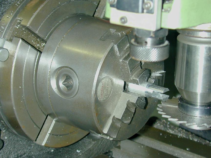
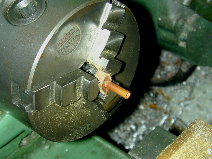 First, the insulator for the fixed-point mount was machined from a piece of resin-bonded linnen stock. As my only stock of this type would produce 20 time more swarf than part, I've cut off a length and cut it into 1/3 cheese slices. These center up well enough in the three-jaw to turn down and drill to the required size.
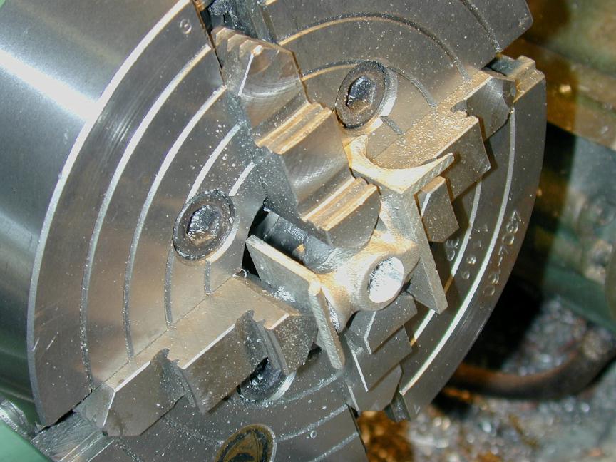
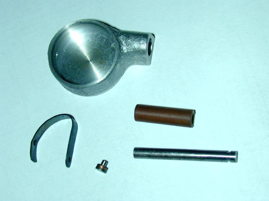 The timer body is lightly cored and can be gripped in the three-jaw self-centering chuck with adequate concentricity (but do check as this is relatively important). The interior is cleaned out, the the body is drilled for a sliding fit on the insulator, and a 1/16" hole drilled for the rivet that will mount the spring moving-point. The spring, seen here is a bit of a challenge to get right, so I made a circular aluminium plug to the ID of the timer, chamfered on one side so the area left open corersponded to the profile of the spring when under tension from the cam. The spring arm was then formed to be a spring fit in the cavity. The orientation of the spring in this photo is 180 degrees wrong, and naturally I riveted it in this way and had to drill out the rivet and start again (grrrr...)
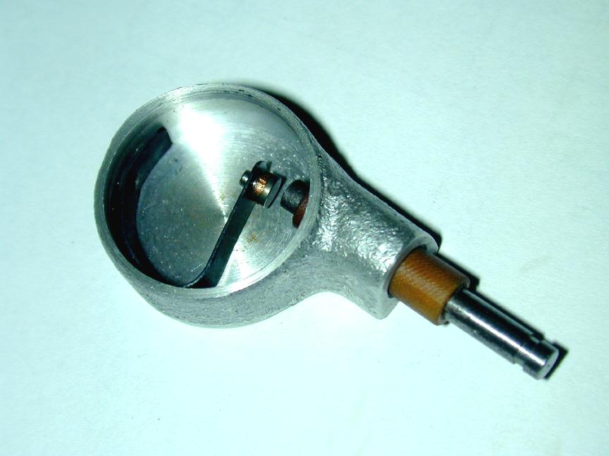 Here we see the correct orientation. The point on the moving arm is one of a small supply of tungsten rivits I have cached away—these being very hard to find these days. There are two cures for this, one is to use polished drill-rod and a transistor assisted ignition system so the current through the points is very low and so pitting is not a problem (tungsten, being hard, is more pitting-resistant). The second is to obtain some tungsten welding rod and turn your points from this. Thanks for this very innovative solution go to a regular reader who emailed me after reading my wails over to point supply situation.
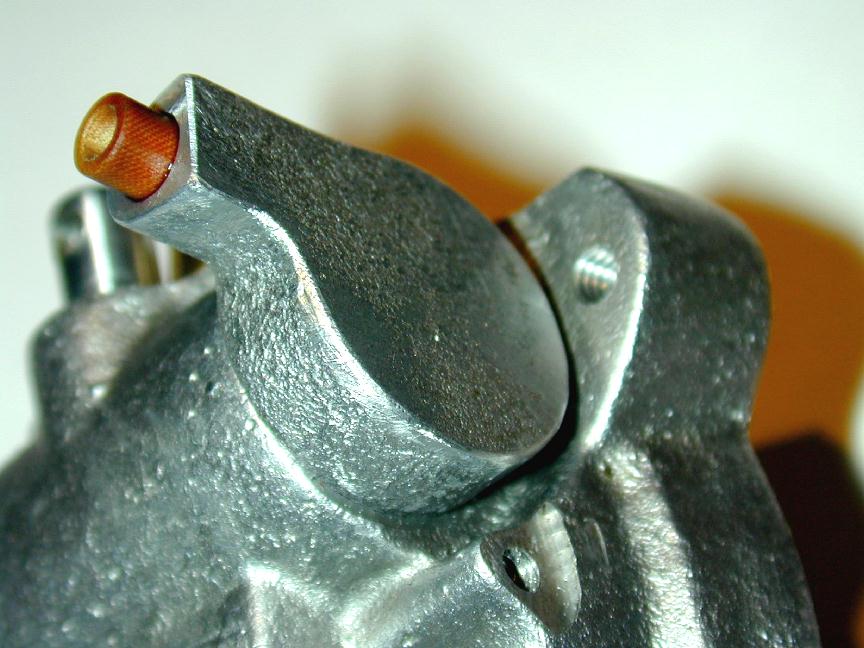 Now the problem. The timer rotates on a thin disk, the same diameter as the ID of the timer body, affixed permanently to the crankcase concentric with the cam shaft. It is retained by a light spring arm screwed to the body by a blind 4-40 tapped hole visible just under the timer in this shot. The problem with how I've machined the case is the timer interfears with the screw that will protrude through the upper lug and provides the means of mounting the engine. No help for it, the timer has to be recessed further into the case.
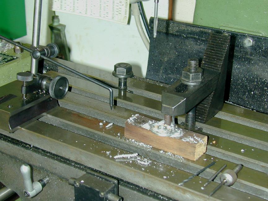
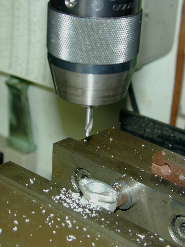
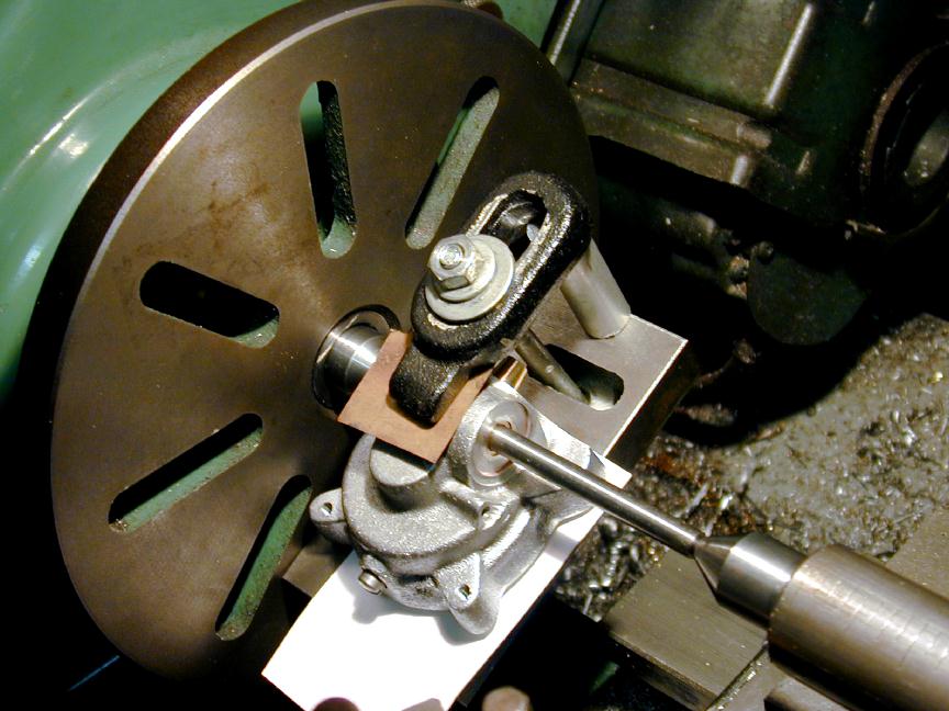 To do this, I suspended the case from a piece of centered 1/4" drill rod mounted between centers. An angle plate was then brought up so the case could be clamped in this position. The centers were removed and the setup checked by clocking the drill rod, now supported by the cam shaft bushing alone. Naturally, before starting this piece of extreme corerction I'd checked I had sufficient thickness in the case that nothing else would be compromised.
 Here we are after the case has been counterbored back so that the spring arm that will retain the timer body will lay flat, or slightly depressed when fitted. The case has been turned away so as to leave the cam bushing exposed. This forms a mount for the thin disk that will be glued to the shaft and act as a bearing against the ID of the timer as before. Actually, this setup is rather better than the kluge I'd set-up previously to mount the timer centering and bearing disk, so all has not been totally negative.
 Finally, we see the completed crankcase modification and the timer retaining spring. While looking at this photo, I realized that the rear of the four lugs must be machined so they are flat and all the same height, relative to the crankase joint to present a true surface to the type of engine mount I had in mind. This has a side benefit of adding another 32nd or so of screw clearance near the timer, as this lug turned out to be the highest of all the lugs (which should not have been a surprice, Murphy being the kind of guy he is).
Carburator
The Feeny carburator was designed to have a choke device reminescent of the rotary barrel of a modern R/C carb, but there the similaraty ends, as the fuel jet was fixed. The history of the Feeney printed in ECJ details how the factory would spin-up new engines with an electric drill and a flywheel, the adjust the height of the jet until the engine would run without the drill. The jet was then crimped in place. Forgive me if I choose to do things a little differently.
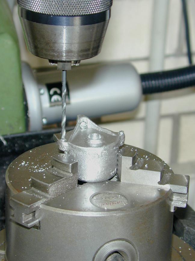
 First, the mounting face of the cored carb casting is milled flat, the inlet hole centered and opened out from the raw size, and the two mounting holes drilled to clear 4-40, symetrical with the inlet hole. Clamping up the job is not too tricky as the top of the casting is flat, and a few bits from the scrap box serve to hold it in place and orientation, firmly enough for the light drilling and milling required.
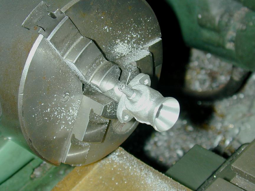 The casting is now mounted on a mandrel turned to be a tight fit in the inlet hole drilled in the previous step. This allows the bell-mouth to be machined. Make sure you machine the opening flat at this step as we need it parallel to the mounting flange for the next setup. Note that the faces of the mounting lugs have also been cleaned up using a ball-nose cutter to provide a flat bearing surface for the mounting screw holes, and to provide sufficient clearance for the screw heads themselves. The little proboscus poking out of the carb body in this photo could have been cut off, and subsequently was. This would have simplified mounting in the previous step.
 The carb can now be chucked up to drill and counter-bore for the slotted "butterfly". Stupidly, I carefully measured the distance of the counterbore axis from the mounting face as specified by the drawings. I should have centered it in the cast boss, so my bore, as seen here, is just a bit off. Not a lot, but enough to be noticable if you look closely (more grrrr).
 The butterfly is turned from aluminium to be a close, but free fit in the counterbored body. Rather than being drilled to the throat bore as we'd do today. the choke is slit to the width and height of the bore. This will probably cause some turbulence and an increase in inlet pressure right at the point where we are looking for a pressure decrease, but as this is not exactly a high performance engine (if it runs at all), I went with the original design which has a degree of charm to it.
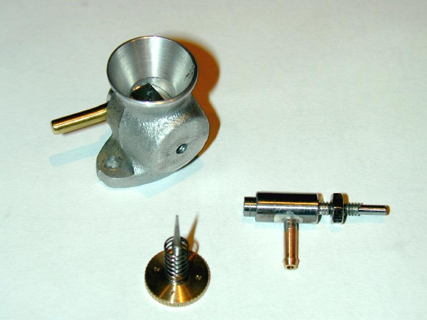 In this show we see the replacement for the fixed jet—and yes, if you think there is a certain ETW feel to it, I can only plead guilty—what can you expect with all the ETW research I've been doing lately
  . It stared as a 4-40 screw with the thread turned off to form the jet spray probe. This has been silver soldered into a steel body, forming the seat for a needle that screws into the other end of the steel body with a 2-56 thread. A fuel inlet intersects with the location of the taper of the needle above the seat region. Not shown is the cut-out quadrant on top of the carb body, milled so the brass butterfly choke arm will be restricted between fully open, and almost fully closed. No adjustment for the closed stop is provided.
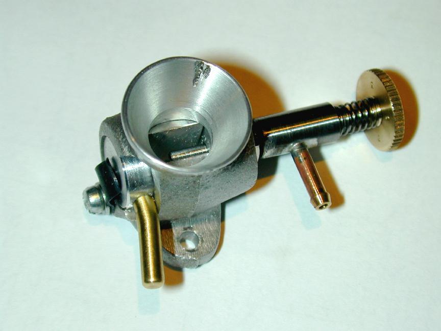 The choke is retained by another light spring arm that is adjusted to provide enough friction to hopefully prevent unwanted rotation. Sadly, my carb casting had a casting flaw, visible at the one o'clock position here, that could not quite be turned away. To complete the little bit of ETW-ism, some numbers were stamped into the visible face of the needle wheel. Too bad they read 1-3-2-4.
![]()