(Last Update November 11, 1999)
Click images to view full size.
![]()
|
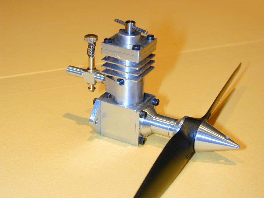
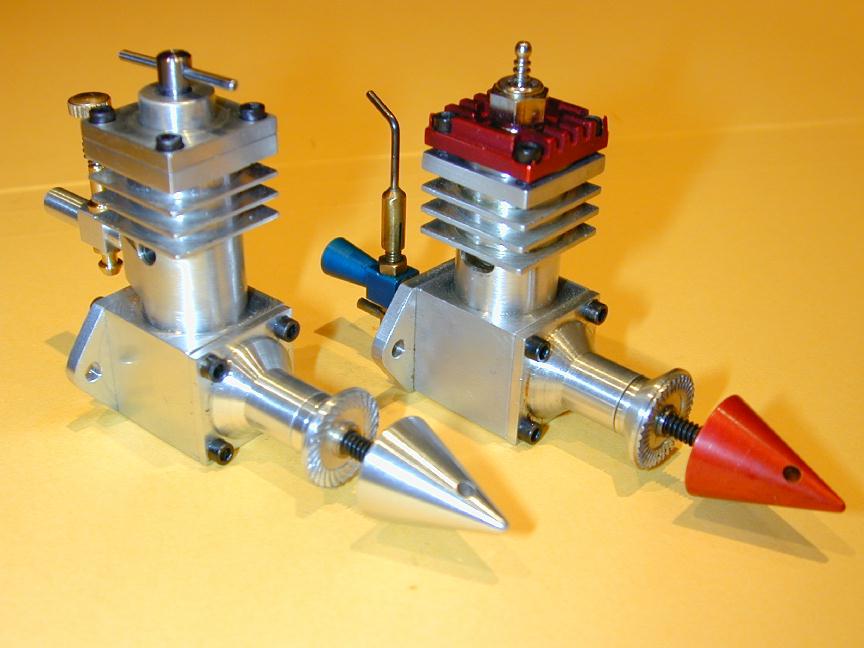
This page presents, in more detail than I'd intended, the building of an EZE-3. The project was started on Wednesday, November 3, 1999 and completed, ready to run, but without decorative anodizing, on Monday, November 8, 1999. I put in a solid working day on the Saturday, but the rest were relatively leisurely evening sessions in the shop. I was quite anal in keeping to dimensions of all working parts, plus virtually all external contours as well. My only deviation was the use of a split cone to secure the prop drive washer and the shape of said washer. It's true about what a single picture is worth. Certainly lots more than my thousands of words. I've just taken a few photos during construction of points that would illustrate what I thought were worthy steps. If there is some particular setup, or process that you'd like to see, email me and if possible, I'll dummy up the shot and add it to the page. Note to builders and prospective builders: The plans for the EZE-3 appeared in the Sep/Oct 1999 issue of MEW. However, the engine requires some parts from earlier EZE drawings. Specifically, the front bearing housing and prop driver from the EZE-1 (MEW, Nov 1998) and the Cylinder head, compression screw, back cover and crankshaft (modified) from the EZE-2 (MEW, Jan 1999). The EZE-3 plans have several dimensions omitted which I'm sure will be dealt with in the pages of MEW in two months time. There are also some "gotcha's" relating to the cylinder liner and head layout. This may be an artifact of the modular design, coupled with the fact that the developer/designer was not the draftsman. So, if you are going to build one, note the following carefully:
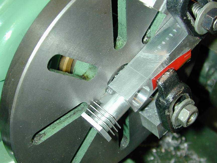
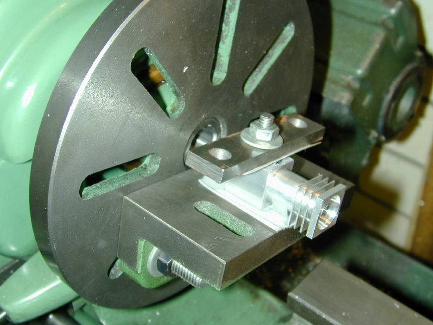
Point 1. An obviously CAD omission. I'm sure it will be fixed up in a subsequent issue addendum. Use 0.562" as shown in the EZE-1 drawings for liner OD and Cylinder bore. Point 2. This item is a bit more serious. First, the liner is a light press fit in the case (needed to prevent crankcase pressure leaking out the exhaust ports). The recess in the top of the crankcase fully encloses the lip on the cylinder liner. This means that there will be no protrusion to grip the liner by to remove it. Probably not a bad idea as this forces one to make a tool that grips something else for this purpose (I don't believe you are never going to want to take it out!). Perhaps the threaded mandrel that screws into the top of the contra piston for lapping will do the job, if the crankcase is heated enough first. The depth of the recess is critical as it establishes the location of the liner ports in relation to crankshaft axis and hence will set the timing. Further, if the recess is just a little too deep, or the flange a little to thin, the head will not clamp the liner to the crankcase allowing it to emulate an uncontrolled sleeve valve (press fit not withstanding). Second, the design calls for the use of the EZE-2 cylinder head which has a recess on its under face 1/32" deep. This was fine when it was used with the EZE-1 component layout, but will prevent the head applying any clamping action here. There are several possible fixes, some involving small but significant changes to several dimensions. The fix that minimizes the interaction is to increase the height of cylinder by 3/64", applying all this increase to the 5/8" diameter top flange. This makes the flange height 7/64" (.109") and permits the head recess to firmly locate the part in the liner and ensures the head screws clamp the liner into the crankcase. Other fixes are possible, but this involves the least changes to other parts. The compression screw from the EZE-2 drawing should be increased by 3/32" in the threaded portion to compensate for the extra height, plus a bit extra. Point 3. As with item (1), this omission will doubtless be corrected by the designer, or someone, in a forthcoming issue of MEW. The port center line is called out using the liner base as a datum. I'd have thought the bottom of the flange would server as a better datum as this is the locating surface. The liner bottom can be anywhere, within reason. Point 4. This problem has existed since the EZE-2 drawings were published and has received no mention - perhaps because it's too "obvious", or perhaps because no one has built one and reported the problem. Simply put, if you add up the dimensions, fore-aft, of all the parts inside the crankcase, they equal the depth of the crankcase. So depending on your building tolerances, the assembled parts may lock up solid, or the crankpin may rub on the backplate. No big deal. Something needs to be reduced by 10-15 thou. Crankshafts should have some end-play when assembled and the prop tightened up - at least 5 thou, but probably not more than 10. At its rear most movement (like when being flicked) the crank pin should clear the backplate - 5 to 10 thou would be adequate. Solution? I found the problem after all the bits were made, so I had to thin down the backplate extension into the crankcase by about 20 thou. This required a rather dodgy setup (no photo - too embarrassing). Better to know about it in advance. I think the best solution would be to thin down the crankshaft thrust face from 1/32" to 1/64" - but you need to know about this in advance too! Point 5. This item is common MICE sense too. The web is not a bearing! (Although some twins have been made like this). So just reduce it to give some clearance. On these last two items, don't go overboard. You should aim to achieve to closest working tolerances you can that will minimize crankcase volume, which maximizes primary compression and assists fuel pumping action (I'm sure there's more to it than that, but I don't know what..) Point 6. The crankcase drawing never really establishes a datum and just plops the venturi mounting boss out in the air, dimensioned, but not positioned. I'll continue talking in fractions, but in the age of A$50 digital vernier calipers, there is no excuse for not working to 3 decimal places. Assuming the recess in the top of the crankcase is 1/16" deep, the boss center line should be 25/32" from the top of the crankcase, or 23/32" from the flange seat (better), or 21/32" up from the crankshaft axis (See what I mean about establishing a sensible datum? Which of those would you rather measure from?). Day 1 (Crankcase):I'm going to try to complete this engine within 10 days of evenings, or less, so I can get back to the Weavers. The photos above show my alternate way of machining the crankcase. The sequence is:
This sequence of operations will ensure that both bores are normal to each other, within the accuracy of your lathe faceplate and angle plate. The turned surfaces may off a bit due to run-out in setup #1 above, but that does not matter. The far simpler sequence of machining presented by Tom in the Nov 1998 issue of MEW obviously works for him as evidenced by all the crankcases he's made, but the above method may be more reliable for those of us who are less experienced than Tom and have all the equipment required. Day 2 (Front and rear covers):
Front and rear covers completed and attachment holes drilled and tapped (see photos 3 and 4). No procedures really worthy of note here, though that won't stop me writing about them. The important part is to machine the front cover to be a tight, sliding fit in the crankcase cavity as it carries the thrashing, reciprocating mass. Be sure to turn the seating face and drill/ream for the crankshaft at the same set-up to ensure the shaft will be at 90 degrees to the cylinder bore. My sequence was:
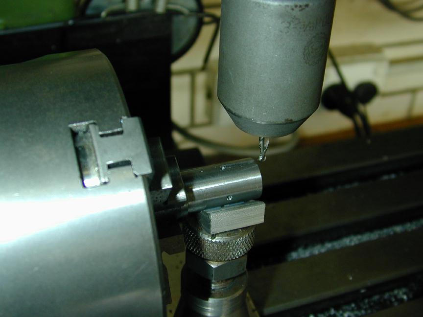
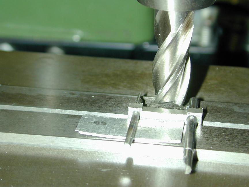
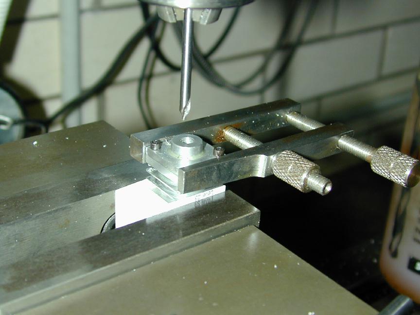
Nothing special in the drilling and taping operation either. How you center up and lay out is dependant on the equipment you have. The most important tip is to make sure everything is clamped firmly. In photo #5, the work sits on parallels in the machine vice with business card stock protecting the finish. I should have centered it in the vice too. Oops. Don't even think about doing this operation holding the work by hand under a drill press! For marking out, I cheat. My mill has a Digital Readout (DRO) that lets me do coordinate drilling of Pitch Circle Diameter (PCD) holes. This is so precise that provided I center accurately, the plate holes and crankcase holes mate up in any orientation. So, assuming you are positioned and working on the front cover, the sequence is:
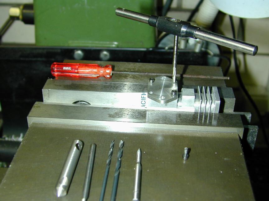
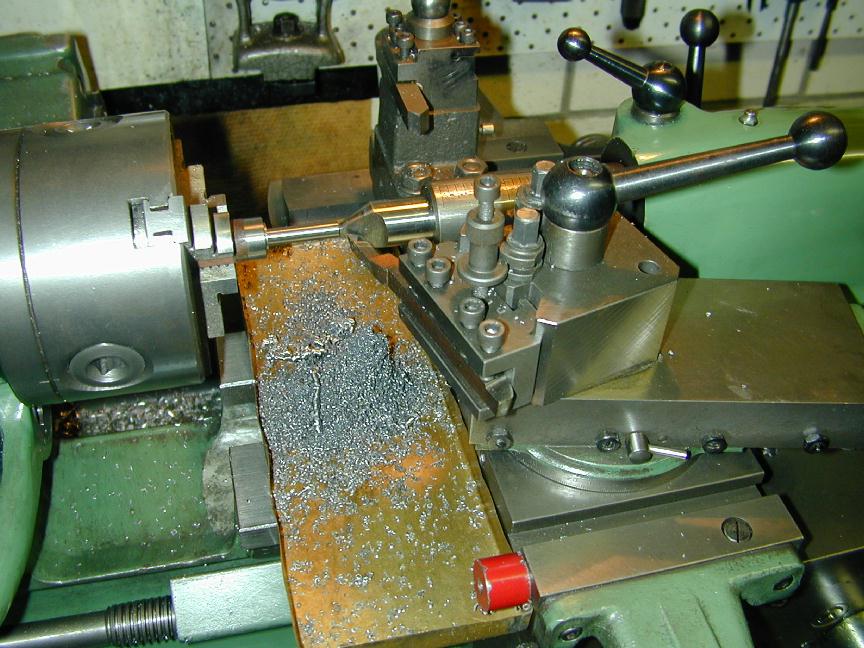
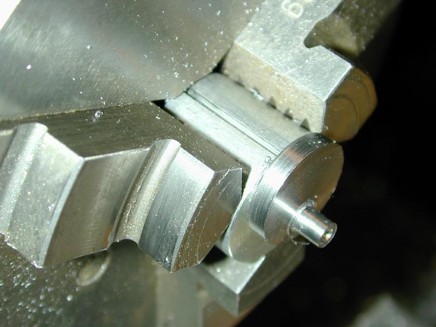
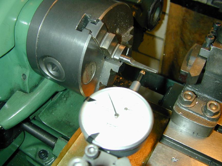
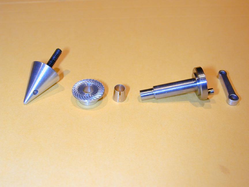
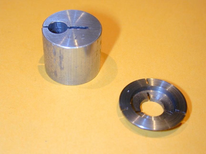
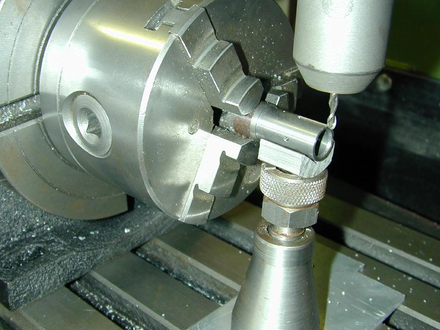
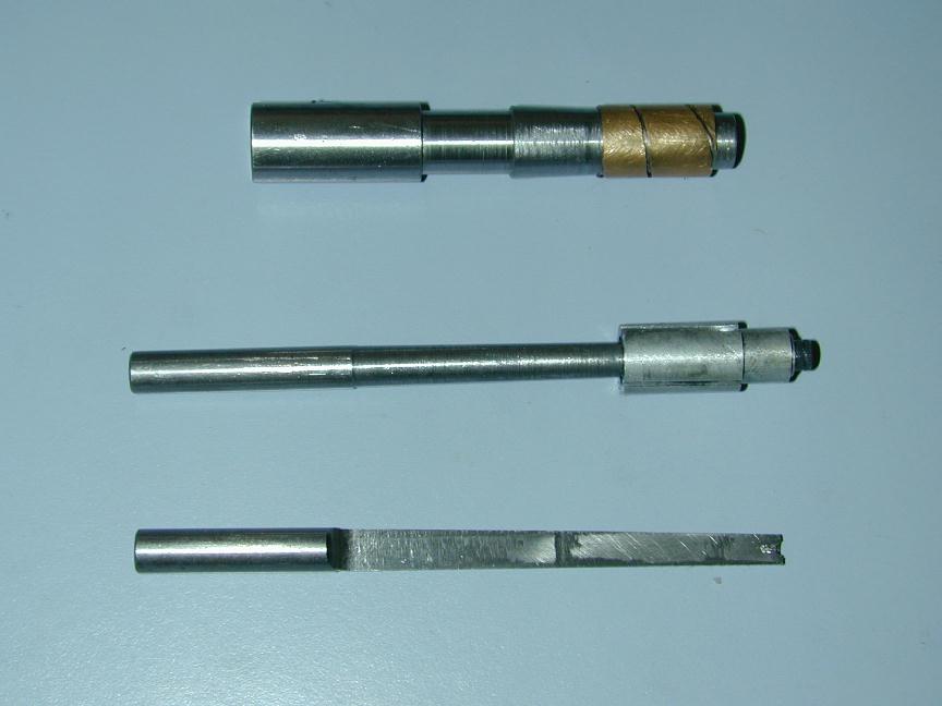
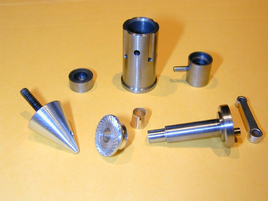
The rear cover sequence is similar although the depths in steps 1 and 2 are different because the cover is thicker. Photo #5 shows the last hole being tapped. I use a Devcon tapping fluid and don't know if this is useful, or voodoo, but I've not broken any taps lately. Day 3 (Crankshaft and prop driver):Beginner MICE express reservations about making crankshafts. They are not that bad, especially small ones, given some simple tooling. Photo #6 shows the first step in the process. This is simple parallel turning. The final 0.001" is removed with a lap. I use an adjustable one made from an English kit that is a duplicate, so I'm told, of the small Delepana external lap. Note the "1/2 center" in the tailstock that allows the tool bit to be positioned close to lathe centerline for these small jobs. The compound slide is set over to clear the tailstock and provide a finer cross feed, if needed. I use 14 degrees which gives about a 4:1 reduction on the compound dial reading. The crankpin is turned in a special jig which is nothing more than a short length of aluminum bar, drilled and reamed off center in the 4 jaw chuck by half the crank throw, then split as seen in photo #14. Take light cuts of 10 thou, from the outside down to crankpin dia, plus 20 thou. Finally, reduce the pin to size and lap for smooth fit in the conrod (or a reamed hole in a test piece). A dead center in the rear of the pin would provide additional insurance against the crank shifting in the jig (interrupted cuts are rough on set-ups), but for something this size, I didn't bother. I've departed from the original design in the prop driver area using a split cone to retain the prop driver. Long ago, I made some "D" bit taper reamers in various tapers. Photo #8 shows a reamer being used to setover the cross slide to match its taper using a plunger style DTI. In photo #9, a length of brass has been drilled 3/16" then taper turned to match the reamer taper. The small cone is next split using the trusty Dremal cut-off wheel (photo #10). The prop driver poses a small work holding problem. The knurling should be done first as this is a violent procedure, benefiting from having the rod stock firmly held in the 3 jaw chuck. The driver blank is then parted off and held in a special fixture so the rear position can be shaped and the hole drilled and reamed to match the split cone. The holding fixture idea came from SIC, where it was called a "pot-chuck". It is more clearly visible in photo 14. In photo 11, the driver has been shaped, drilled and is being reamed. Trial fit using the shaft/housing/cone assembly in the developing tapered hole. If anything, aim for too little end-play in the assembled parts. You can always pop the driver back in the pot-chuck to face back the driver for correct shaft end-play, but you can't expect it to line up well enough to ream it out more. The conical spinner is shown being finished in photo #12. It has been faced (rear), drilled, tapped and cross drilled before being threaded onto a stud in a scrap jig for taper turning. The included angle is 20 degrees. I think this shape harmonizes well with the taper on the front bearing housing and the prop driver. All the finished parts are shown in photo #13. The stud is a sawn of 6-32 Allen head cap screw (using that trusty Dremel tool, again). Day 4 (Cylinder, Piston, and Rod Assy):
The cylinder is quite simple to make. My machining sequence was:
The cylinder lapping process is another deep mystery to new engine builders that is really simple. Photo #19 shows two styles of laps. The one on top was used to lap the EZE-1 cylinder. The lower one was originally made to lap the cylinder of my first home made engine - a Sparey 0.8cc (sic). I reused its mandrel, with a different lap, for the EZE-3. It's a long, tapered mandrel onto which fits an aluminum (or brass, or cast iron) plug of diameter a shade under the un-lapped bore. This is split lengthwise with a hacksaw and carries two sawed grooves at 120 degrees to the split. These act as combination oil damns, chip collecting drains and expansion assistors. A small piano wire pin in the mandrel engages in the groove, preventing the lap from twisting on the mandrel. A screw and coller on the end push the lap up the mandrel where the taper causes it to expand. The taper reamer at the bottom is made from drill rod, hardened and tempered. It is used to ream the lap to match the mandrel before splitting. The lap is "charged" with diamond lapping paste (fine grade) by squeezing the merest dab onto some fully hardened tool steel, then rolling the lap around on it, embedding the grit into the surface. In use, the lap is spun at around 200 rpm and the cylinder stroked up and down it with lots of fine grade oil. The aim to smooth out the bore and introduce a small taper (no more than 0.001" for this engine), uniformly, from bottom to top so the piston goes tight towards TDC. This is done by feel and is a skill easily acquired. Now call me Scottish, Jewish, or just plain mean, but I have a problem with taking a piece of SG cast iron rod, 1-3/4" in diameter (the smallest I can buy), that is hard to locate and costs a fortune, then reducing it to less than one half and inch in diameter to make the piston! A while back I hit on this Uncle Scrooge solution. Saw off a piece of rod, then saw that radialy into three 120 degree segments. Each one will make a piston up to 0.5" diameter. The shape grips well in the 3 jaw chuck and apart from the interrupted cut while you're banging the corners off (use a roughing tool, not your finishing tool), the method is quick and painless. Photo #17 shows such a lump being turned to circular for the piston and contra piston. After turning to within 0.001" of the bore measured at the TOP of the liner, drill out the blank for the piston interior, then over to the rotary table on the mill for gudgeon pin drilling and remering. Back to the lathe to part off, then drill and tap the contra piston interior. Part this off next and we're ready for lapping. I use holding fixtures very similar to those Tom describes in the Nov 1999 MEW to hold the piston and contra piston for lapping. Photo #17 shows the contra piston on its fixture being lapped. Note paper to protect the lathe bed and the little adjustable external lap which is worth its weight in Microsoft founder stock. The lapping process screws the part up tight on the threaded mandrel, but you just tighten up the lap on it and it acts as a soft clamp to loosen the part. It's interesting to note that the gudgeon pin diameter has been reduced from the 1/8" called out in the EZE-1 plans, to 3/32" for the EZE-3. I thought the previous size was massive overkill, but discovered during my research of the Little Dragon that it too, had a 1/8" wrist pin, but used brass tube as the material. Finally for this session, the conrod is drilled, reamed and contoured. Both holes must be done at the same setup to ensure they are parallel. This is where a mill, or a vertical slide for your lathe is a major asset. It lets you drill and ream one hole, then move precisely to the location for the next. Photo #20 shows the profiling in progress with the rod sitting on two drill rod "D" bit reamers, shimmed up so the rod sides will taper, bottom to top. Final rounding is started on a sanding table and finished with needle files and burnishing belt. If the output for this session seems very productive, it was a Saturday, so maybe it should count as two days work :) Day 5 (Cylinder head and venturi assy):
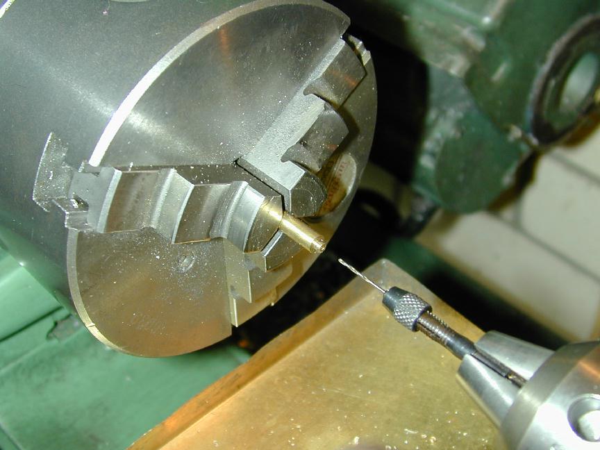
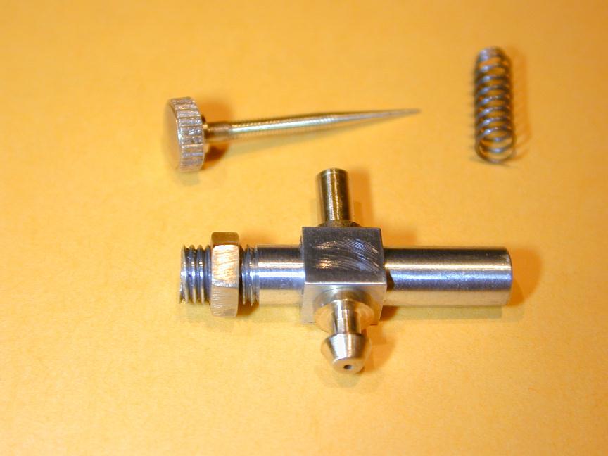
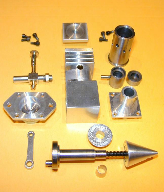
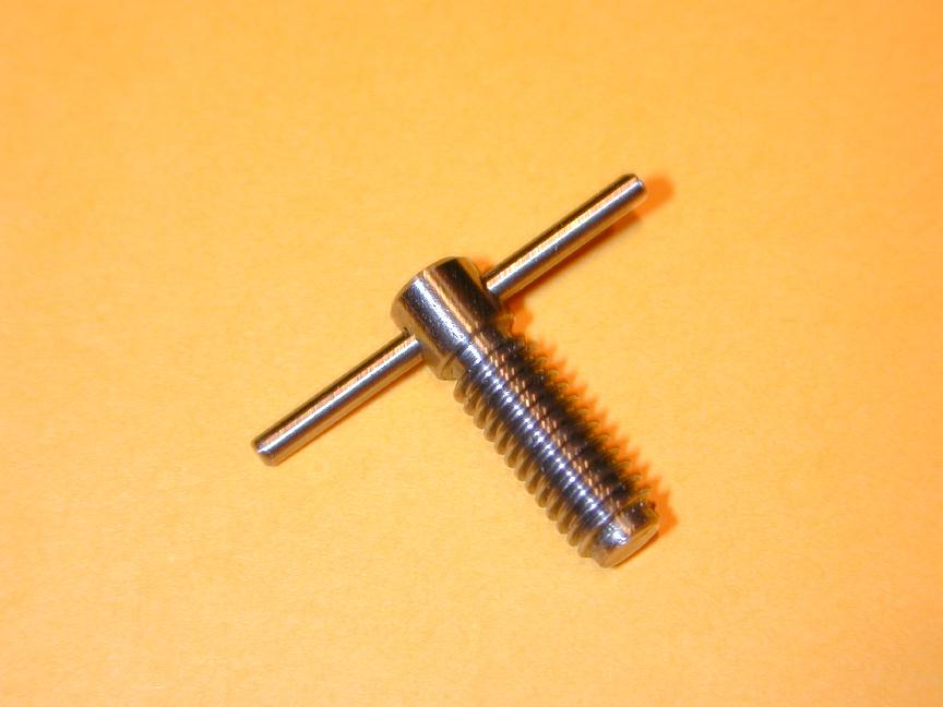
The cylinder head is simple turning. The holes will be omitted until the liner is in place and they can be drilled into the crankcase in the same way as were the front/rear cover holes. The undrilled head can be seen in the back of photo #24. The venturi is simple, but tiny. I have no 1/4" aluminum plate to spare, so I turned the venturi from 5/16" diameter K&S stock, then milled the center section square, drilling and tapping 4-40 for the spray bar bits at the same setting. the 4-40 (6BA) size was chosen because the tap drill size in #42, which is just smaller than the venturi ID of 3/32". The little spray bar parts are simple, but require some precision because of their size. Photo #21 shows the fuel jet being drilled #70 using a pin chuck held in the larger chuck. make many small cuts, completely withdrawing the drill each time, brushing the chips from the flutes and you'll have no trouble. The upper spray bar was drilled through #54 and tapped 1-72 for the needle valve. The needle was taper turned with a 16 degree included angle as shown on the plan, from a length of 0.071" K&S brass rod. This was then threaded 1-72. The top knob was turned from 3/16" brass and the needle Lok-tited into it. A little burnishing on top and it looks like it has been made from the solid! Photo #22 shows the completed assembly. The spring provides operating friction and was wound from a length of old guitar "B" string. That was the output for Sunday afternoon (I worked about the same amount of time I would spend in an evening session). At this point, only the compression screw assembly needs to be made and the head attach holes drilled and tapped. The completed parts are shown in photo #24. Day 6 (Compression screw and final assembly):
The comp screw (photo #24) is too simple to describe, except the threaded portion could stand being extended by 3/32", or so, from the length (7/16") shown in the Jan 1999 MEW. Mine, made exactly to the dimensions sits totally buried in the head. Before final assembly, I give all the parts a good shake 'n bake in the ultrasonic cleaner. I tell myself this will get any residual diamond specks etc out left behind after lapping, thus prolonging engine life. This could be more voodoo, but I do it anyway. The assembly sequence was:
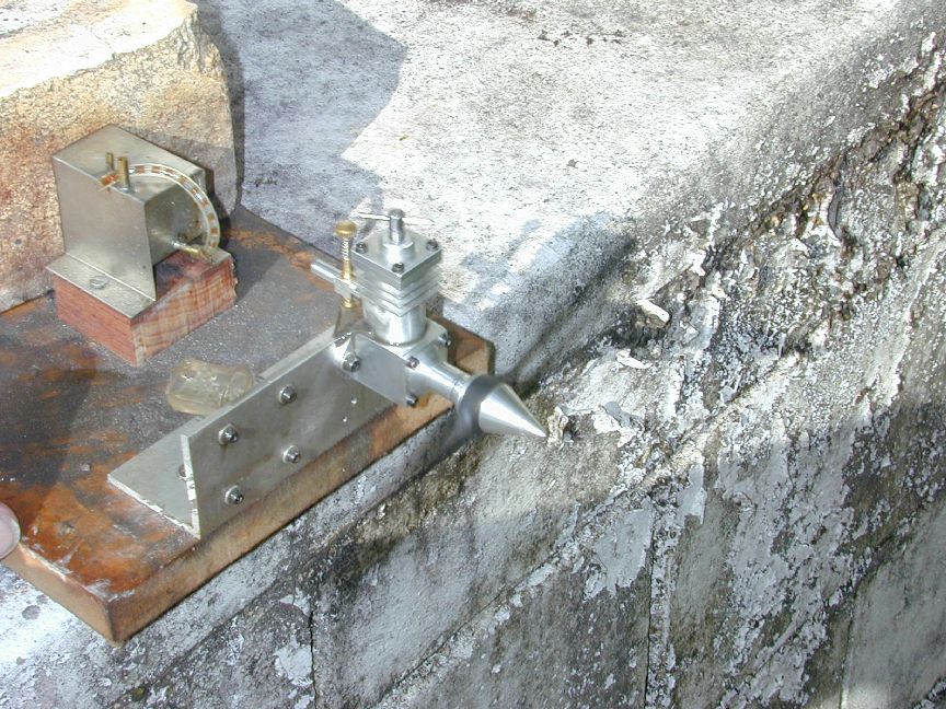
Squinting through the ports, I see the piston just reaches the bottom of the exhaust port (and transfer ports) at BDC and just fully opens the intake port at TDC, so I guess my "guess" regarding seating location of the liner and the diameter for the inlet port were correct. At this point, it has good compression and the contra piston moves firmly down and snaps back up when backed off. Maybe that liner won't have to come out, after all! I'd say that it feels like a happy little diesel, so far.
The measured EZE-3 specs are:
|
![]()