Photo #1 EZE-1/2 Crankcase . |
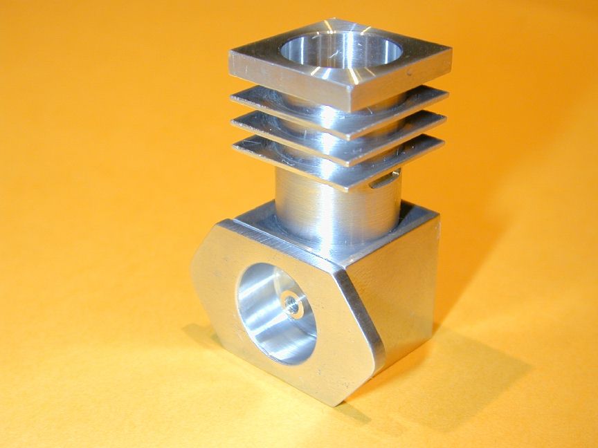
Photo #2 EZE-1/2 Backplate (before drilling) |
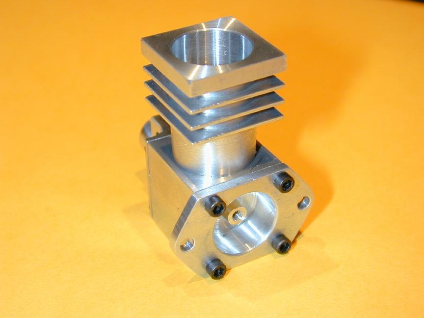
Photo #3 EZE-1/2 Backplate (after drilling) |
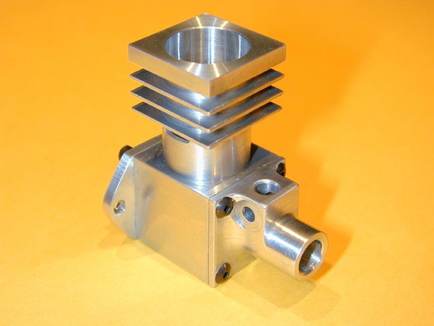
Photo #4 EZE-2 Front Bearing . |
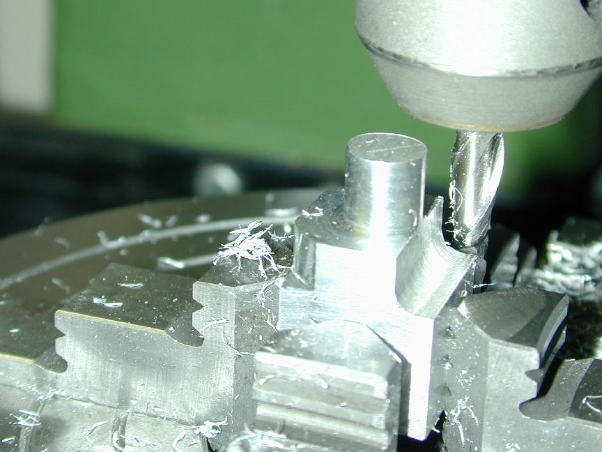
Photo #5 Intake machining First pass |
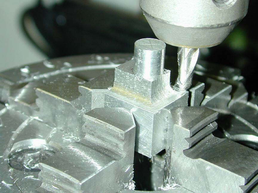
Photo #6 Intake machining Third pass |
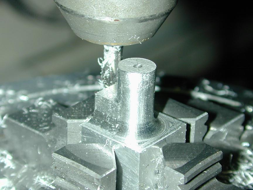
Photo #7 Intake machining Radial pass |
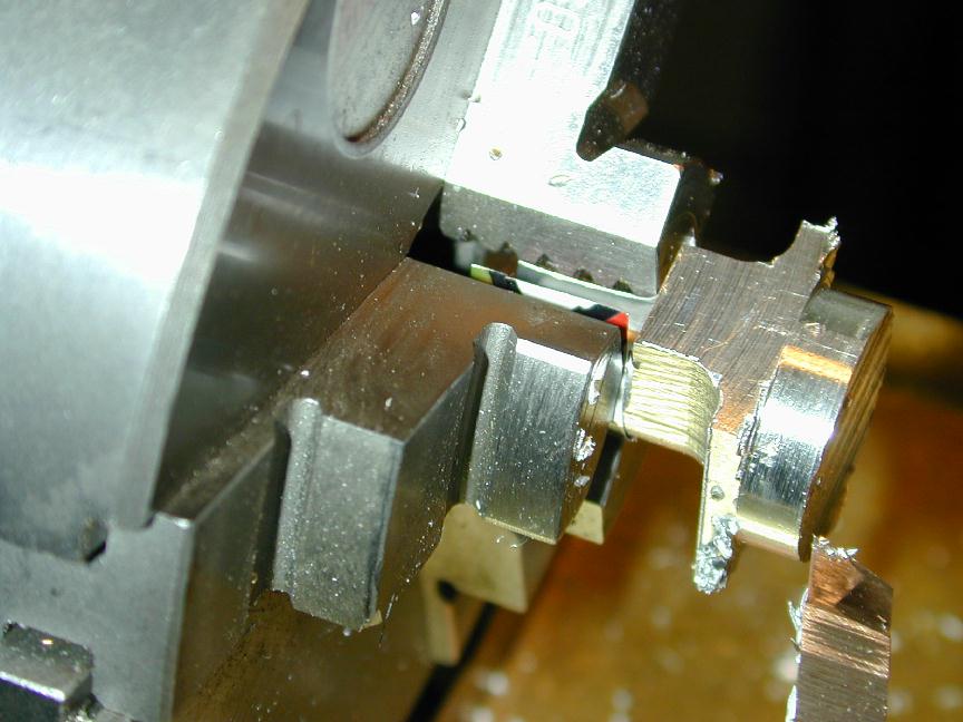
Photo #8 Turning register . |
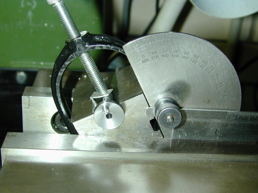
Photo #9 Crankshaft port setting up |
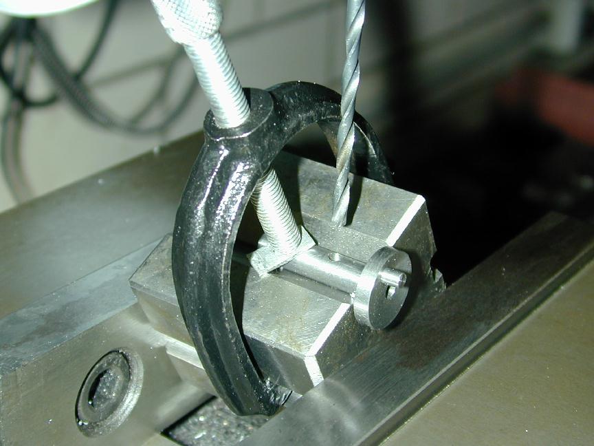
Photo #10 Crankshaft port drilling |
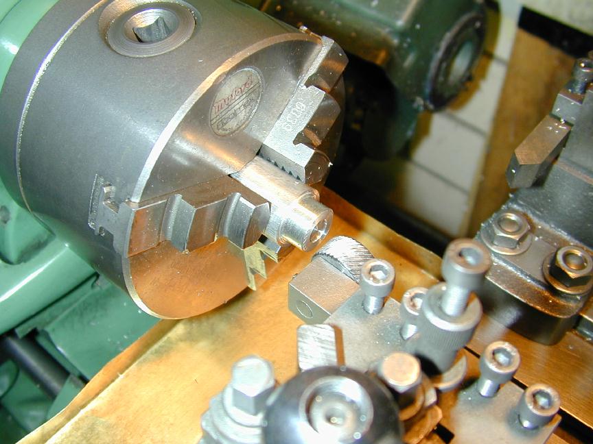
Photo #11 Driver knurling setting up |
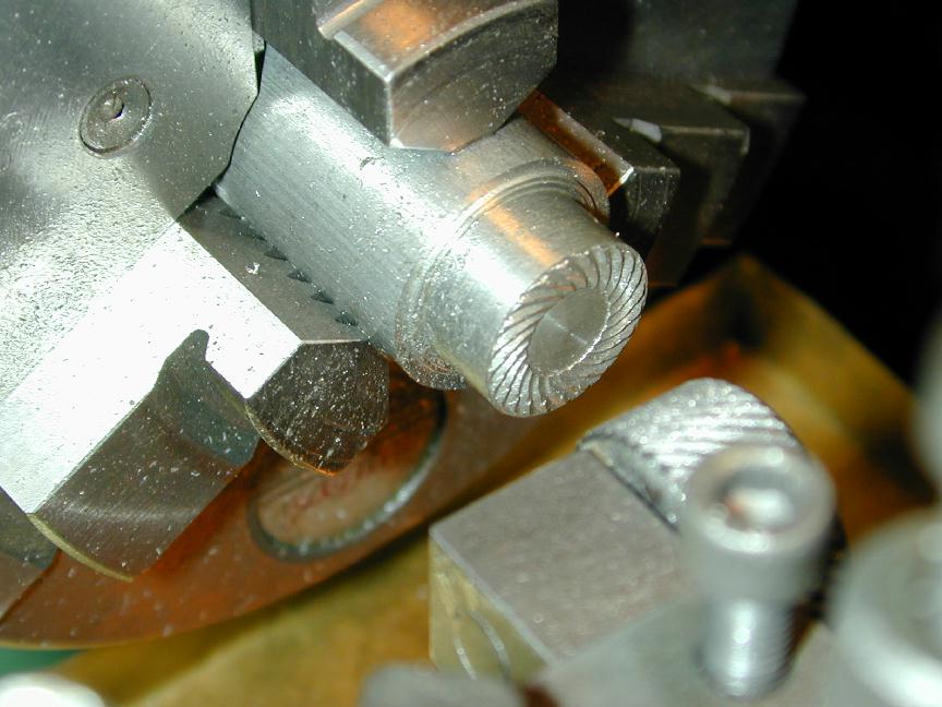
Photo #12 Driver knurling complete |
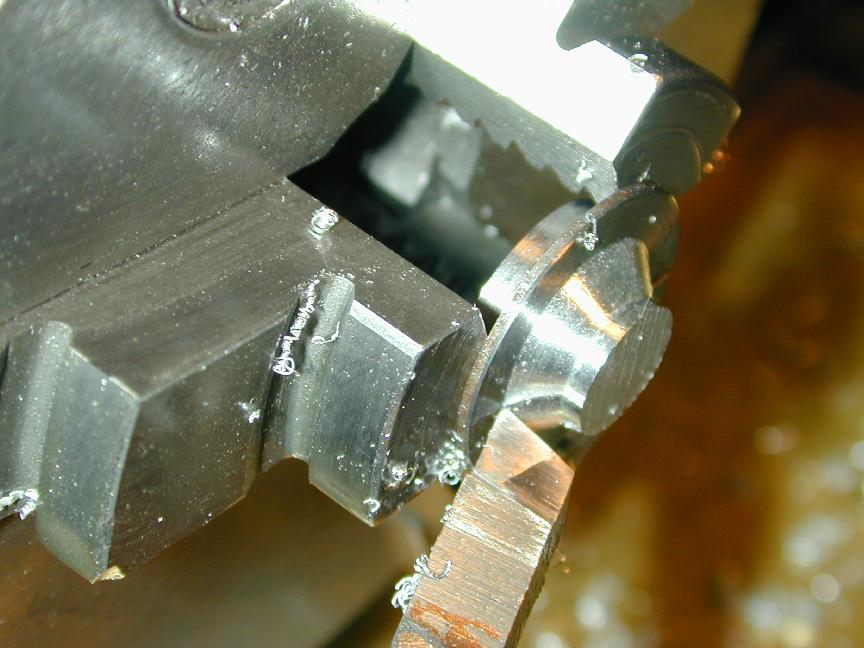
Photo #13 Prop Driver in pot chuck |
Photo #14 Spinner nut cross drilling |
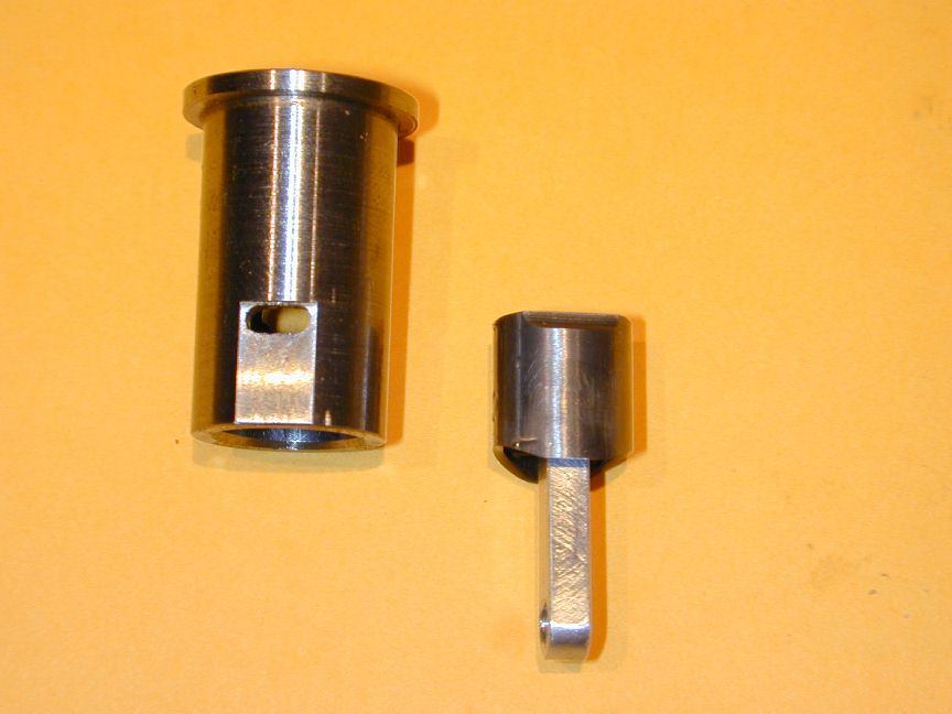
Photo #15 Cylinder liner and Piston |
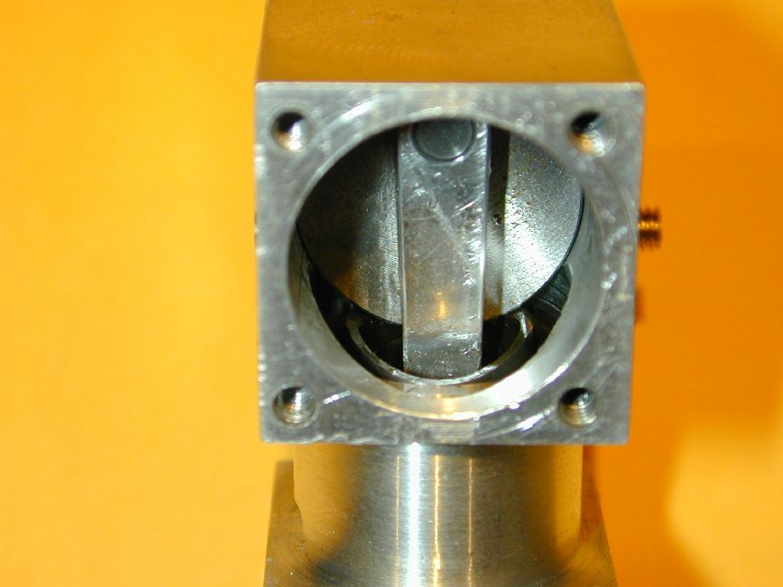
Photo #16 Piston clearance at BDC |
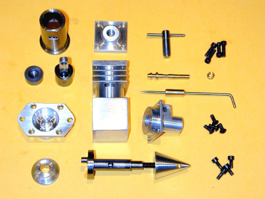
Photo #17 Exploded View . |
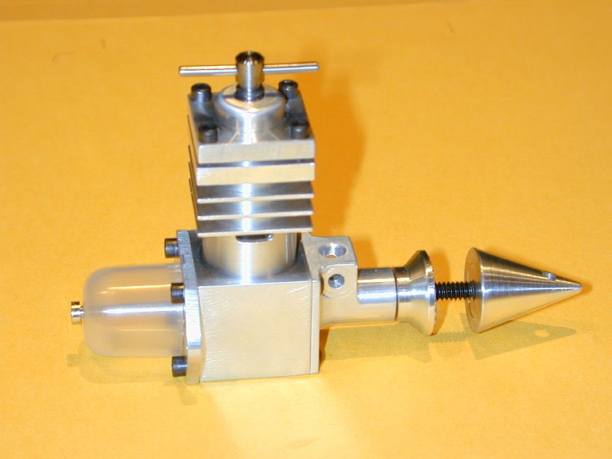
Photo #18 Trial fit of molded tank |
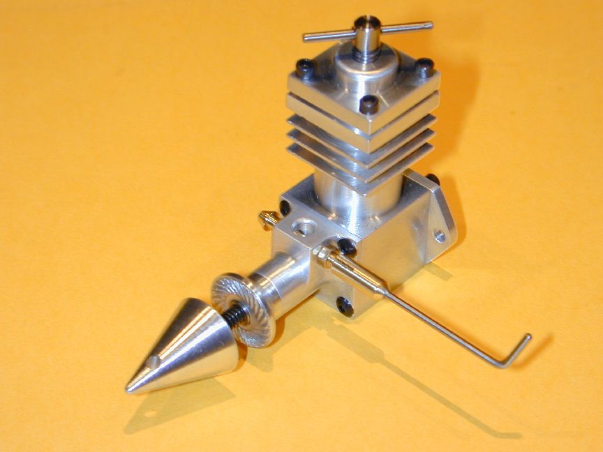
Photo #19 Front left view . |
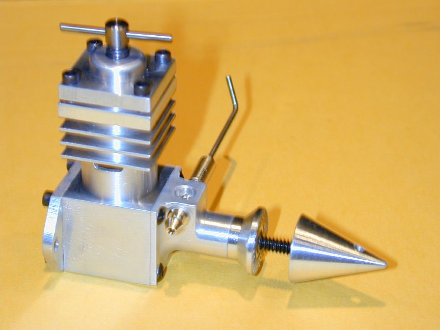
Photo #20 Front right view . |
The EZE-1 and EZE-3 were made in about a week of evenings apiece. If I can maintain the rage, the -2 should go together the same way.Then I can really get back to work on the Weavers. This page will be just photos and any truly salient comments (as if I can keep my mouth shut). For a more detailed construction write-up, visit the EZE-3 page.
Day 2
About the only part for this engine I've not made before (for the -1, or the -3) is the front bearing and induction housing. Would you guess it? There's a dimension missing. Now I've done enough CAD to know this happens. I've also done enough CAD to know the cure is to have other people check your work. 'Taint happinin' here, folks! The omission is minor, but indicative. It relates to the size of the intake protrusion.
The location of the center line of inlet hole is given as 11/32" from the thrust face of the housing. I'd have chosen the rear face of the mounting flange as the datum. This would make measurement easier (3/16" from a flat face), if nothing else. What's missing is any indication of the distance from the hole center line to the front face of the venturi protrusion. No big deal. The hole is 5/32" dia, so it needs to be half that, plus some. I added on 1/16", making the distance from the face that mates with the crankcase 0.328", or 21/64".
I may as well describe the machining sequence I chose to produce this part, but I stress one more time: I am not a trained, professional machinist and my way is neither the only way to do it, nor probably the best way. But it worked for me and it may work for you.
- Center a length of 3/4" square stock in the 4 jaw chuck with at about 5/8" protruding.
- Turn down to 3/8" dia, 3/8" long. This is longer than final size (0.266"), but we are going to reverse this part in a 3 jaw chuck, so a bit more to hold onto will be a good thing.
- Transfer the chuck to the rotary table, set horizontal under the mill and establish the center of the 3/8" dia section. Rotate until the square is aligned with the mill X-Y axis.
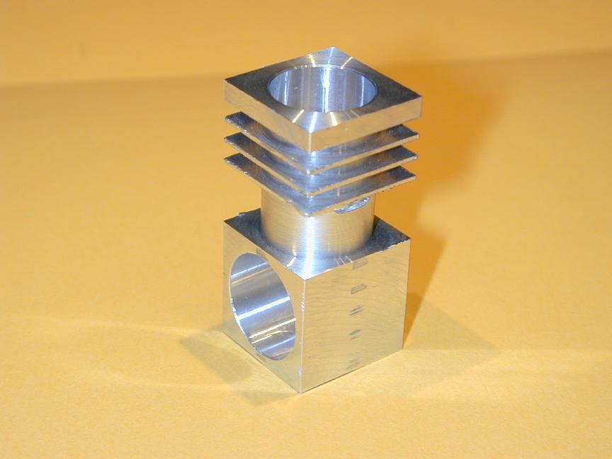
- Using a 1/4" ball end slot drill, mill away 3 sides 0.281" deep until the mill just kisses the turned portion. Note the X reading of this operation (see photos #5 and 6).
- Now zero the Y axis and offset the X by (-) the amount recorded above; ie away from you. Best to do this with the downfeed locked from the previous operation. Orient the part with the intake boss pointing to the left.
- Wind the rotary table clockwise through 270 degrees to complete contouring the intersection of journal and attachment flange - see photo #7. Note that the sequence described ensures "climb" milling which will produce the smoothest finish (I don't like to do a lot of filing and sanding).
- Remove from the 4 jaw chuck and saw off leaving just over 1/4" from the front face of the mounting flange.
- Mount on the lathe in a 3 jaw (self-centering) chuck, gripped by the 3/8" dia x 3/8" long journal. I wrap aluminum shim (drink can) arount the part to protect the finish.
- Turn down to approx 0.625" for a firm, sliding fit in the crankcase until the mounting flange is about 0.050" thick, taking light cuts and using plenty of kerosene as cutting lubricant (see photo #8).
- Center drill and drill through "B", followed by "C", then ream 1/4" dia (see EZE-3 instructions). This hole may not be exactly in the center of the journal, but that does not matter. It will be very close and it will be at exactly 90 degrees to the attachment flange and thrust face - that is what does matter.
- Face back the 0.625" spiggot until it measures 0.156" from the attachment face (see why that's my preferred datum?). Finish by chamfering at 45 degrees for about 0.005" to ensure the crankshaft thrust face will ride on the front bearing thrust face.
- Transfer the chuck and work back to the rotary table on the mill, set vertical this time, and align the part with an engineers square against one of the flat sides, venturi upper-most.
- Center the part under the mill (X-wise) and measure 0.188" (3/16") from the mounting flange to locate the inlet hole. Center drill, then drill 1/8" followed by 5/32" being carefull as you break into the crankshaft bore.
- Keep the Y axis locked and rotate the table 90 degrees. Position 1/8" from the top of the inlet face, center drill and drill thru #33 for the spraybar (Drill two sizes smaller (#35) first to get an accurate hole size).
- At the same X-Y setting, spot face 1/4" on both sides for the spraybar with an end mill.
- Remove from the chuck and measure overall length to determine how much to remove so the part will be 0.750" long. Back to the lathe, reverse the part, gripping on the 0.625" spiggot (use shim) and very, very carefully, reduce back by the amount calculated. This is a delicate setup and I recommend 0.005" cuts. Takes a while to remove 1/8" that way, but if the tool digs in, you'll be sorry!
- Remove and finish up with light filling and 600 wet and dry (wetted with light oil) to remove all machining marks. Burnish up on a Scotch-Brite (tm) belt, or similar - see photo #4.
If you look very closely at photo #7 you'll see two tiny pyramids I've missed. I figured these would be flattened during drilling and spotfacing, so I didn't bother (and yes, they were). You may've seen some CAD/CAM maching centers that produce extremely complex 3D shapes doing contour milling with ball-end mills, direct from three view drawings. Amazing!
The drawings show sharp intersections around the venturi. I've radiused everything. It increases the amount of work and requires spot-facing the spray-bar faces as described and the mounting holes as well (see photo #4). I think the result was worth it, but the design as drawn would be perfectly satisfactory and easier to make.
Day 3
The only defference between the crankshaft for the -2 and the -3 is the the need to drill the intake port in the EZE-2. Photo #9 shows how I decided to setup to do this. The crankshaft has been set in a small "V" block with the pin in the TDC location. This was done with the help of a DTI reading against the pin (tune for maximum smoke, as we used to say in amateur radio). The V block is then set at the correct angle in the machine vice with a small protractor - 28 degrees in this case. Double check everything three times before drilling - remember, the hole needs to reach TDC before the crankpin when the engine is rotating counter-clockwise, viewed from the front. Finally, center drill the follow with #33 and #31 drills, taking care as the drill breaks through into the central transfer passage (photo #10).In the EXE-2 article, I kinda glossed over the prop driver knurling operation. With a little practice, it's easy to get quite good results. Here are a few tips:
- Machine a little raised band about 12 thou high where all the knurling will take place (photo #11).
- Not obvious in the photo is the knurl axis is not perpendicular to the lathe axis. It is inclined so it will bite deeper on the outside. This is because the knurls are not paralel ridges, but pie shaped wedges and the gullies between them are the same - so they must slope up towards the center. You can actually calculate the angle required, but with experience, you can eyeball it. If you don't do this, the knurl will not be clean.
- Run the spindle at about 300 rpm and plunge the knurl in (I feed the carrage in with the leadscrew hand wheel), applying lots of kerosene and brushing like crazy to clear out the chips which will mar the knurl. It helps to run the lathe in reverse while doing this so your brush will be "rejected" by the job, rather than be "sucked in". After you start, it's best not to disengage the knurl until you're done. You can stop periodically to see how things are going.
- When happy with the depth and shape, brush the job radially with a bronze wire brush. It really cleans up stubborn chips. Notice how in photo #12 the outside and inside perimeters of the raised area have been mashed. Touch these up with a sharp tool before removing.
That's all there is to it (plus practice). On these drivers, I've used a one half of a "diamond" knurl set on center height. The resulting pattern will grip a prop well for driving, but in retrospect, it would probably be better if they faced the other way so they bite into the prop during back-fires, thus preventing it from unscrewing. I'll remember next time; maybe.
Day 4
As per schedule, this session produced the cylinder, piston and several contrapistons! It also uncovered yet another drawing mystery. The -2 uses the cylinder liner from the -1 which has a flange on top. This flange is called out as 1/16" thick and 0.688" in diameter (11/16"). By contrast, the diameter of the flange on the -3 is reduced to 5/8" (0.625"). The cylinder head of the -2 has a 1/32" deep recess on its underside intended to register on the liner flange, but this is dimensioned 5/8" which will fit the -3 (that had not been published when the -2 head appeared), but not the -1 liner that it was intended to mate up with.
Now none of these things are any big deal, however they serve to illustrate a point highlighted by one reader in the "Letters to the Editor" column. Namely, when preparing a CAD drawing, the value and importance of a General Arrangement. This is especially relevent with plans targetted at trusting, first-time builders. CAD GA's are simply produced by taking the parts already drawn and fitting them together, cross sectioning where appropriate. Because this is a cut 'n paste operation, if the drawn bits don't go together, neither will the parts made from those drawings. Enough said.
Photo #15 shows the completed cylinder liner and piston, viewed from the transfer port perspective. Note the use of a milled baffle on the side of the piston which uncovers the cylinder transfer port shortly after the exhaust port opens. The baffle causes the new fuel/air charge to be deflected upwards, minimising loss through the open exhaust, while forcing out residual burnt gasses remaining in the top of the cylinder. The transfer process is refered to as scavenging and engines such as this that use a piston baffle are sometimes called "Loop Scavenged" designs.
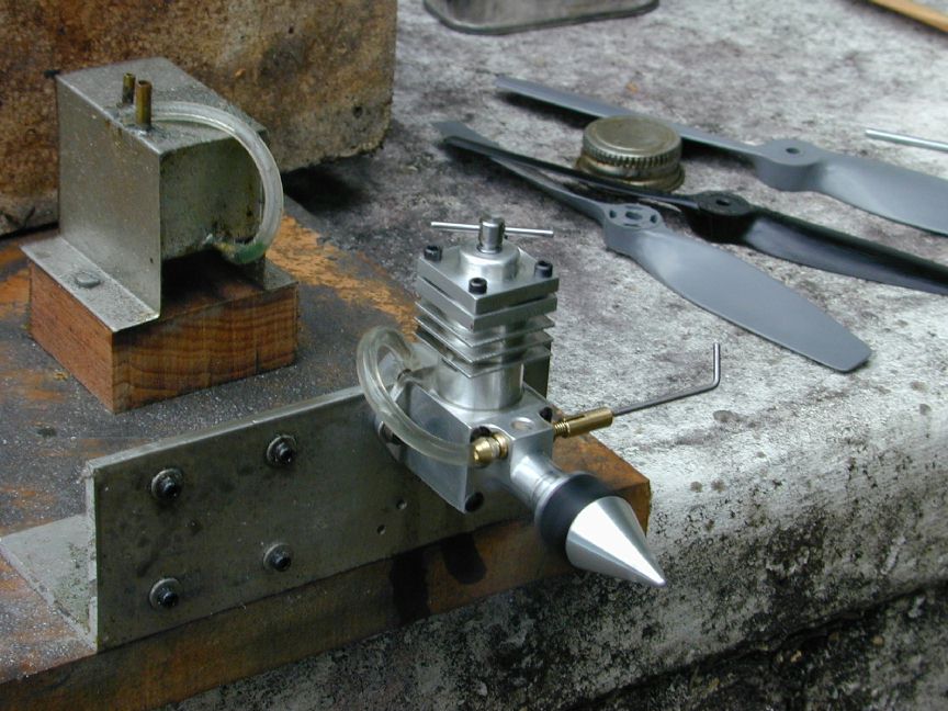
Photo #16 shows the crankcase interior, viewed through the open backplate, with the piston at Bottom Dead Center (BDC). Note here how the piston skirt contouring just clears the crankshaft web. The last photos show the complete engine, both assembled and exploded. I've made the needle valve and spray bar to conventional practice, which took a lot longer than the far simpler approach presented with the EZE-1 plan.
Another minor design departure is the spigot left in the middle of the backplate cavity. This is blind drilled and tapped to carry a bolt, or stud, that will secure a small plastic tank. A trial fit of the tank is shown in photo #18. These tanks are injection molded from some type of poly-somethene material and are available currently from Owen Delta Engines in Australia, or from Barton Model Products in the UK (ie, the editor of MEW himself). If you want to make your own exactly like this, buy Dave Gingery's book "Secrets of Building a Plastic Injection Moulding Machine" available from Lindsay Publications. Even if you don't build it, this is an interesting book. Hmmm. Wonder if my tank was once a plastic milk container?
The measured EZE-2 specs are:
- Bore 0.409"
- Stroke 0.375"
- Capacity: 0.049 cu in (0.8 cc)
- Timing:
- Exhaust
- Transfer
- Intake
- Weight, including spinner, excluding prop: 68 gm (2.39 oz).
Performance (prop and RPM):
- Cox 7x3.5 7200
- Master 7x4 6900
- Cox 6x4 7800
- Winston 6x3 8800

Photo #21
EZE-2 Spinning
6x3 at 8800RPM.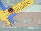
Photo #21
Brown paper
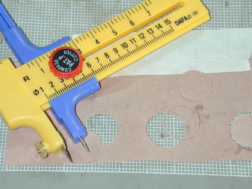
gasket makingThe -2 started easily, handles and performs well - as can be seen in photo #21. Hot starts are no problem. I initially experienced some leakage around the front crankcase joint, so I made a brown paper gasket using a little circle cutter I found in an Arts and Crafts store (see photo #22) which cured that little problem. All in all, I'm quite pleased with the -2 which runs as well as it looks. It is the lightest of the three and the best performer (based on the statistically invalid sample of one each!).