The Napier "Deltic" Engine
Details of a noteworthy development in the designof high efficiency internal combustion engines.
By Edgar T. Westbury
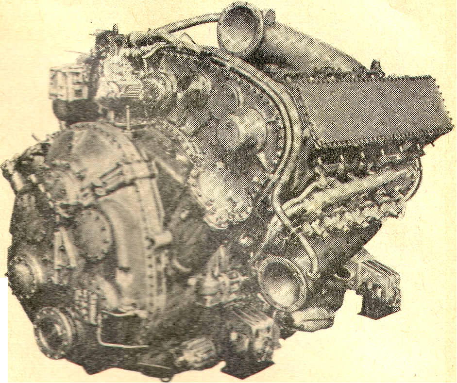 A view of the "Deltic" engine from transmission gear end |
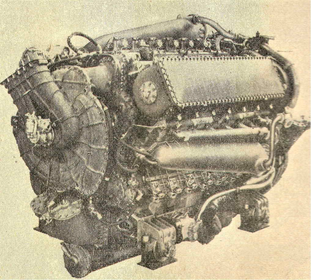 Reverse view of engine, showing centrifugal scavenging blower |
Although opinions may differ as to the value of articles in The Model Engineer on the subject of "prototype" engineering, which are sometimes criticised on the grounds that they have no direct bearing on the problems of model construction, there is reason to believe that most readers do take a very keen interest in full-size engineering developments, and articles on this subject have been very popular in the past. Constructors of model locomotives, ships, aircraft, etc. can obtain not only authentic information, but also inspiration and new ideas, from a careful study of drawings, photographs and descriptions of the full-size prototype.
The case is not Quite the same, however, with that problem child of the engineering family, the internal combustion engine, in which it is extremely difficult, or even impracticable, to produce a successlul scale working model of the most advanced types of large engines, and superficial representations, such as are popular in the case of the other objects mentioned, hold little appeal to the constructor.
I have followed closely the development of full-size engine design, but have rarely ventured to comment upon it in these pages, because the more immediately important matter of keeping up to date with demands for information on the construction of model i.c. engines has been more than I can properly cope with. However, I have recently encountered a new type of engine which I believe to have far-reaching possibilities, and which embodies most interesting features of design, so that I feel sure there are manv readers who will welcome a detailed description of it, even if there appears to be little prospect of exploiting these features in a working model. Furthermore, this gives me an excuse for writing an essay on the elements of engine design. which I hope many readers will find instructive.
In company with a number of other representatives of the technical Press, I was recently privileged, by courtesy of the Chief of Naval Information, to witness an impressive demonstration of the engine in Question. and also to take a cruise on an ex-enemy E-boat in which two of the engines have been installed for seagoing tests.

Contrary to views which have often been expressed lately, the introduction of the internal combustion turbine has not stopped development of the reciprocating type of engine, which for many practical reasons is likely to be with us for many years yet. The lessons of the last war have emphasised the importance of engines of high powerweight ratio for light, fast naval vessels, and the engine to be described has been developed, from basic proposals submitted by Mr. N. Penwarden, a draughtsman at the Admiralty Engineering Laboratory, by Messrs. D. Napier & Son, Ltd., on behalf of their parent company, the English Electric Co. Ltd. After prolonged tests, it is now in production, primarily for the purpose stated above, though it obviously has a much wider potential application, for other types of marine craft, locomotives, stationary work, and even aircraft.
The engine is of the two-stroke type, employing the opposed-piston principle, having 18 cylinders, and producing 2,500 b.h.p. A 9-cylinder version of half the power has also been produced, and the design is applicable to any multiple of three cylinders. It is designed to run on oil fuel, with solid injection and compression-ignition, but could equally well be adapted to run on gas or petrol, with normal carburation and spark ignition.
Cylinder Arrangement
The basic principle of design on which this engine depends is its particular disposition and arrangement of cylinder groups, and to understand the reason for, and the advantages of, this feature, a brief review of the way in which multicylinder engines have developed may be of interest. In all i.c. engines of substantial size or power, it has been found an advantage, and sometimes a necessity, to depart from the policy of developing the power in a single cylinder unit, and to duplicate or multiply the number of cylinders, operating on a single crankshaft or a system of cranks geared to a common output shaft. The reasons for this are various, and include convenience in dealing with heat and mechanical stresses, balancing, and compactness; but perhaps the most urgent practical. reason is to promote smooth, even running by improving uniformity of turning moment, or as it is often technically expressed, low ratio of maximum to mean torque.In this respect the i.c. engine differs radically from the stearn engine, as in the latter case a singlecylinder double-acting engine has a frequency of power impulses, in relation to shaft revolutions, equal to that of the normal four-cylinder four-stroke i.c. engine as commonly used in motor cars, and though it is not impossible to improve upon this comparison, it is rarely convenient. Generally speaking, multiplication of cylinders of steam engines , is adopted mainly for purposes of compounding or expansion staging.

Of the various cylinder arrangements, the most obvious, and most commonly employed, is to dispose them parallel and in line with each other; alternatively, they may be placed in double banks, in vee or horizontally-opposed formation; or triple-banks, as in "trident" or Y formations. The latter may be developed into star or radial formations, either in a single row or banked. More uncommon arrangements, using two or more crankshafts geared together, are the "square four," and the "H" type engine, the latter having two compact horizontally-opposed banks of cylinders one above the other. All these arrangements have their own particular virtues and limitations; for instance, the straight inline engine is convenient to produce, and reasonably accessible, but it produces a long engine, tending to lack structural rigidity unless heavily built, if more than about four cylinders are used. Double-banked engines are stiffer in structure, and are used successfully for a larger number of cylinders, up to twelve or, possibly sixteen, but are more complex and less readily accessible.
Radial engines are compact in a foreand-aft direction and enable a short, stiff crankshaft to be used, but they have a very large frontal area, and are unsuitable for most purposes outside aircraft. Incidentally, the geometry of these engines makes it desirable to use an odd number of cylinders to obtain equal firing intervals, jf they are of the usual four-stroke type.
Opposed-piston Engines
Apart from the disposition of the cylinders, their individual design is another important consideration. Most four-stroke engines of high efficiency have their valves in the head, and this form of design may almost be said to have become conventionalised nowadays. Twostroke engines have not been in favour for high power, except for heavy marine practice, but in the course of their development they have produced at least two very interesting departures in cylinder design, both of which have the unusual feature of two pistons to one combustion chamber; namely, the .. split single" and the opposedpiston arrangement. The latter is not confined to two-stroke engines, but is particularly applicable to, and generally associated with them. On the face of it, the primary advantage of this arrangement is that it enahles perfect dynamic balance to be obtained by the opposition of equal opposing forces at equal velocity, but it has other properties which are just as important in practice. The first is that it enables the scavenging of a port-controlled two-stroke cylinder to be vastly improved by introducing unidirectional air flow; the second is that it eliminates the fixed cylinder head, as such, the reaction thrust which this component would normally absorb being taken by a moving member. It may be observed that in the development of high power engines, the thermal and mechanical stresses on cvlinder heads have often caused considerable trouble, and have given designers many headaches. The opposed-piston engine has long been the dream of the inventor seeking the elusive "idea! " engine, but in spite of its undoubted advantages, it has been a difficult engine to adapt to practical requirements.It calls for either a crankshaft at each end of the cylinder block, the two being synchronised by gearing, or a cumbersome system of connecting rods; in either case it is likely to become a bulky and awkward-shaped engine. There are several well-known examples of opposed-piston engines which have been highly successful, including the Fullagar, Doxford, Oechelhauser, and Junkers, the latter having been adapted to aircraft propulsion, but it has always been a problem to build and install them compactly.
The "Deltic" Engine
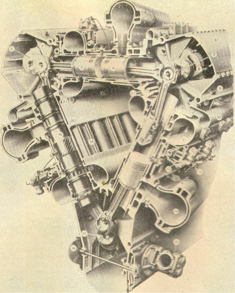
In this engine, the particular virtues of the opposed-piston engine have been combined with a unique arrangement of cylinders, which enables it to be built compactly, packing a very high power into a relatively small bulk and weight, and at the same time making all working parts readily accessible for servicing. The inherent simplicity of the valveless two-stroke is retained, with its high mechanical efficiency, as the loss of power normally entailed in driving the valve geacing is eliminated. While thele are no new theoretical principles involved in the design, the combination of desirable features cannot fail to impress the practical engineer; but what is more, it undoubtedly gives the desired results.The arrangement of the working parts of the engine are clearly shown in the sectional illustration, where it will be seen that the cylinders are disposed in the form of an equilateral triangle, with three crankshafts located at the apices. Each crankpin is connected to two pistons, working in adjacent cylinders, the big end bearings being of the fork and blade type, so as to avoid geometrical errors which would arise if the articulating centres were not co-axial. The three crankshafts are geared together so as to run at the same speed, two running in one direction and the third (in practice the lower shaft) in opposition, timed in correct phase, so that the pistons alternately approach and recede from each other as the shafts rotate. One piston in each cylinder controls the inlet ports at the outer end of its stroke, and the other the exhaust ports; the pistons are not in truly opposite phase, the exhaust piston having a 20 deg. lead so that it opens and closes its ports earlier than the inlet piston. In this way the exhaust pressure is released before the new charge is introduced, while on the other hand the exhaust ports are closed before any substantial escape of the fresh charge can take place. The inlet ports are cut at an angle to the wall the cylinder so that the gas enters tangentially, producing a rotary swirl which is effective in cleansing or "scavenging" the exhaust products from the cylinder.
Along each bank of cylinders, near the centre of its length, runs a camshaft which operates the fuel pumps, which are of the usual metering type, with spill ports, controlled by rotating the plungers, to inject the quantity of oil required; in this respect they follow the normal diesel engine practice, but the pumps are not made in the usual form of multi-plunger unit. Each pump is virtually a separate unit, situated as near as possible to its cylinder and delivering fuel to two injection valves of the outward-opening type, by short pipes, all of equal length.
The cylinder liners are, of course, open at each end, and are not subject to stresses in an endwise direction, so they need only to be located at one end, water seals in the form of rubber rings being provided at the other end and around the port belts. In the region of the combustion chamber, the liners are reinforced by thickening up, and spiral passages are provided on the outside for the circulating of cooling water. The bores are chromium plated and lapped.
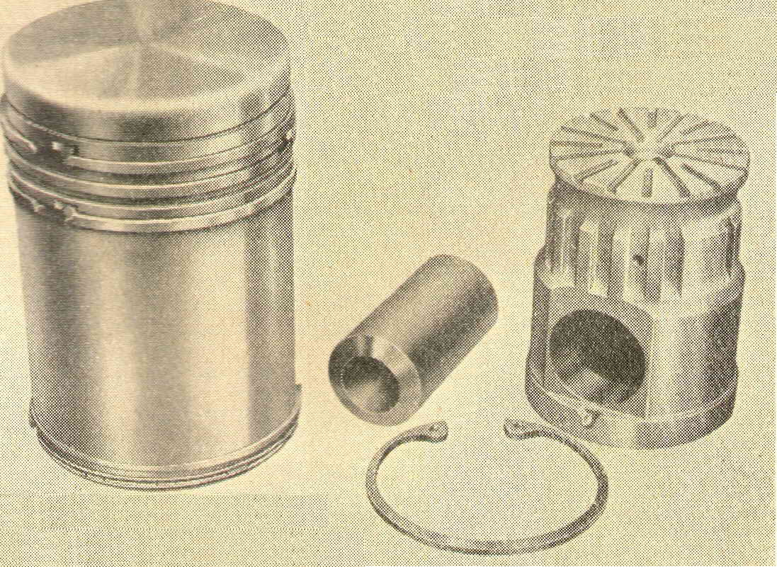 A patented form of piston is employed, the main object of which is to assist cooling by lubricating oil from the inside. The construction of the piston js of great interest, because somewhat similar forms of pistons have been used in model practice, though for a very different reason. It consists of two main components, the outer of which, of light alloy with an inserted ring of austenitic iron to carry tbe two top piston rings, is tUrned all over, and an inner member is fitted. baving a cross hole to take the gudgeon-pin, and a system of grooves through which the oil passes to cool the inside of the piston head, being continuously replenished by fresh oil fed to the gudgeon-pin bearing by way of drilled passages through the connecting-rod. Both pistons in each cylinder are identical in shape and size, but one transmits more power than the other because of the phase difference, and therefore each crankpin is connected to one inlet and one exhaust piston in adjacent cylinders.
Scavenging Blower
Air is supplied to the inlet belts of all cylinders by a centrifugal blower of the double-entry balanced type, gear driven from one end of the engine, and coupled by flexible shafts, running at a little over five times crankshaft speed. It delivers air at about 8 lb. per sq. in., in sufficient volume to fill the cylinder displacement plus wastage, but is not normaIly intended to act as a supercharger in the true sense of the term.From the structural point of view, the design of the engine is very attractive, the working stresses on each triangular unit being taken by tension bolts which extend from one crankcase to the next, through the cylinder block, which is in one piece for the complete bank of inline cylinders in each case. Thus the entire unit is inherently strong and rigid. The engine is arranged apex downwards, which is convenient and accessible, but could be disposed in any other position, or with any alternative method of mounting, if required. A closedcircuit cooling system is provided, in which distil1ed water is passed through the jackets, and cooled by a heat exchanger, through which sea water is circulated by a gear pump. An oil cooler is also pro-vided. The mechanical arrangements for these and other services follow normal practice, and all auxiliary drives are taken from the transmission end of the engine.
For the purposes of marine propulsion, the engine is provided with a built-in gearbox giving forward and reverse drives, control being by means of a two-way hydraulicaIly loaded plate clutch. The reverse gear has a lower reduction ratio than the forward gear, but in cases where it is desirable that a pair of engines should be "handed" so as to drive propellers in opposite directions, this can be done by using an alternative assembly of the gears interconnecting the three crankshafts.
Starting is effected by a combustion type starter, in which a cartridge is fired into a piston, the endwise movement of which operates a shaft through helical splines, the latter carrying a claw or face ratchet which engages with a similar ITlember on the engine shaft. Five cartridges are carried in a rotating breech like the chambers of a revolver, and fired electrically as required, one " shot" normally being sufficient to start the engine from cold.
Cross-section Through One Bank of Cylinders
 Key:
Key:
- "BC" crankshaft
- "BC" crankrose
- Inlet piston
- Exhaust piston
- Crankcase breather
- "AB" crankcase
- "AB" crankshaft
- Main bearing cap
- Crankcase tie-bolt
- Drain oil manifold
- Air inlet gallery
- "A" camshaft casing
- Fuel injection pump
- Exhaust manifold
- Sea-water pump
- Fresh-water pump and pressure oil pump drive gear
- "CA" crankshaft
- Cylinder block tie-bolts
- Cylinder liner
- "C" cylinder block
- Blower flexible drive shafts
Leading Technical Details
| Shaft Horse Power: | ||
| Maximum | 2,500 at 2,000 crankshaft r.p.m. | |
| Continuous | 1,875 at 1,700 crankshaft r.p.m. | |
| Net Dry Weight: | ||
| Engine only | 8,725 lb. = 3.5 lb. per h.p. | |
| Engine with reverse gear | 1O,5OO lb. = 4.2 lb. per h.p. | |
| Overall Dimensions: | ||
| Length (engine and reverse gear) | 10 ft. 11 in. | |
| Width | 6 ft. 2-1/2 in. | |
| Height | 7 ft. 1 in. | |
| Cylinder Data: | ||
| Cylinder bore | 5-1/8 in. | |
| Stroke | 7-1/4 in. | |
| Swept volume, total | 5,384 cu. in. (88.3 litres). | |
| Swept volume, Effective | 5,300 cu. in. (86.9 litres). | |
| Piston speed at 2,000 r.p.m. | 2,416 ft. per minute. | |
| B.M.E.P. at maximum power | 91.9 lb. per sq. in. |
Reference:
The Model Engineer, Percival Marshall & Co. Ltd. Volume 108, Number 2713, May 21, 1953, p622.
![]()

This page designed to look best when using anything but IE!
Please submit all questions and comments to
[email protected]