Editorial
One thing you don't see (often) in the pages of Model Engine News is people's faces (unless they've died). It may be a personal thing, but it's beyond me why magazines dedicated to technical subjects, especially those of the printed variety, waste valuable content area by printing the "smiling head and shoulder" shot in the space where the readers would prefer a gory detail of the mechanism. Foremost in this category, I name the Experimental Aircraft Association's monthly mag, Sport Aviation. More recently, the venerable Model Engineer has succumbed and not only are we subjected to the editor's mug every month, but that of his staff and the contributors, some of whom look decidedly uncomfortable about the whole thing. The EAA is worse though. I've been a member since 1968 and even hard bound early volumes which contained pictures of aircraft under construction, the tools and jigs used, and ones showing how problems were solved. Now all we see proud owners posed beside the wing (plus the Association staff H&S shots, ad nausium). Instead of reading and binding 'em, now I scan and bin 'em. This is not to say that the person who has built or restored any light aircraft has no reason to be proud; they have every reason! I'm only saying that this little brown duck would be more impressed at their efforts when presented with images of how and what they did. Save the facebook stuff the those with no life please.

Now where am I going with this rant—or this month's rant if you prefer? Well, as a preface to breaking my own number one rule, naturally. Here we waste space on the smiling head and shoulders shot of moi posed in a Robinson R44 just before going off on a trial instruction flight on July 25 last. The flight was Ruthie's Christmas present from last year and was just the best time I've had in ages. With around 1,000 hours in command of light fixed-wing singles, flying the R44 turned out to be easy, after I got used to the very light hydraulically boosted controls. Seeing this, the instructor cut short the fun "over water, not above 1,000" part down the Australian Gold Coast beaches and took us back to the helipad for some hovering. Flying just "the peddles" in the hover was easy. Flying the collective was a bit harder, but manageable. Finally, with the instructor flying the pedals and collective, he gave me the cyclic. That turned out to be a humbling experience which none of my fixed wing, nor model 'chopper experience helped with. So am I signing up for a rotary wing license? Maybe, maybe. It was a LOT of fun and if you have the chance, do it!
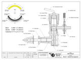
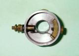
Ok, last H&S shot you will see here for the foreseeable, promise. On other fronts, I actually got into the shop this month to make a fuel tank and feed nipple for the AHC "00" prototype. What spurred this burst of enthusiasm was Adrian Duncan's work on one of the "production" AHC's I made ages ago which he acquired from eBay. His review of the AHC will appear here later this year and includes a BHP curve that is somewhat disappointing when compared with the Deezil, an engine which would have been a contemporary and competitor had the AHC gone into production. Adrian had some difficulty finding a stable needle position on his "08" engine and cured this by making a new feed nipple to replace the "genuine original" AHC part which did not reach the venturi bore by a couple of threads. Refer to the GA to see what we mean.
Adrian's theory was that this caused pooling of fuel in the venturi resulting in poor atomization and heating of the mixture due to conduction of cylinder heat. His new nipple cured the setting problem and seemed to make the engine run cooler. This got us talking (by email) about the design and ways we could further improve it. We decided to undertake some experiments where I'd send him the RRV and updraft FRV versions for comparison testing and I'd make a new case with a screw-in venturi for the prototype so we could test the result of running the same engine mechanics with an original cast venturi and that from my Deezil. The casting of the AHC severely restricts the inlet diameter, but as Roger Schroeder found in his analysis of the engie which appeared in ECJ, correcting one design limitation just exposes the next, so we are not expecting miracles. Still, as Gordon Cornell pointed out in his excellent series on Model Engine Development, focus on one thing at a time. Take some repeatable measurements, form a theory and some way to prove it, make a single change, then re-test and evaluate. This will take a while and we'll report the observations and conclusions separately from the AHC review. Should be fun.
Vale: Myford

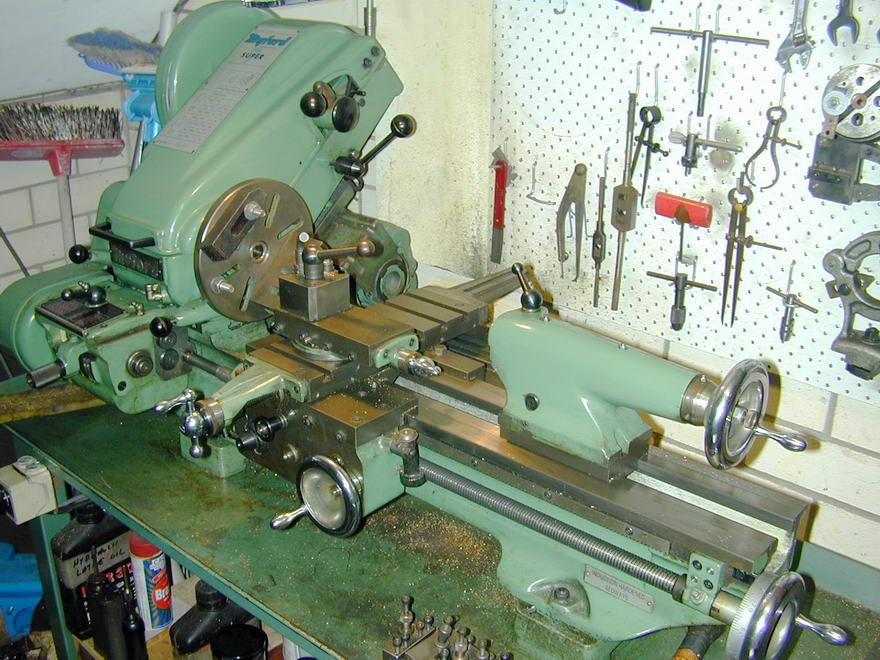
I can't believe I'm writing this. Information is still very scant, but it appears that as you read this, Myford's "Liquidation Sale", which included plant and equipment, will be over and the maker of what I believe to be the finest model engineer's lathe ever produced will be no more (pun). As far as I've been able to determine, no actual press releases or "official" statements as to why this move was taken have been made public. The various Internet forums are full or rumor and speculation, some quite wild, but all we really know is that the founder, Mr Cecil More, died on the weekend of July 9 and the recently revised Myford web site posted the liquidation sale notice for the weekend of July 16 shortly thereafter. Even though the event is now past, the notice remains.
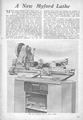
More founded the Myford Engineering Company in September 1934. A good history of the company and its products can be found on Lathes.co.uk, so I won't try to précis it here. Their most revered product must be the ML7 and it's descendents. This lathe was first announced in the Model Engineer of Thursday, February 21, 1946 (Vol 94 Issue 2337) and became the lathe to own or aspire to amongst the readership with a justified reputation for quality, precision, and robustness. At this time, spares are anyone's guess and it is probably one of life's ironic coincidences that in June 2011, legal action by Myford Ltd for "passing off" forced a company operating as the Myford-Emporium Limited to close. Seems this lot, apart from borrowing the name without permission, had been supplying unauthorized Myford compatible spares and accessories deemed by Myford to be of substandard quality (See ME Vol 206 Issue 4405, 3-16 June, 2011). Wonder if they will magically resurrect now?
I'm not going to speculate on why the family decided to close the doors, though I will report facts when and if they become known. In the meantime, my orphaned Super 7 will carry on, though there may be the sound of the occasional muffled sob emanating from the empty machine shop.
Oil Bath
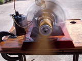
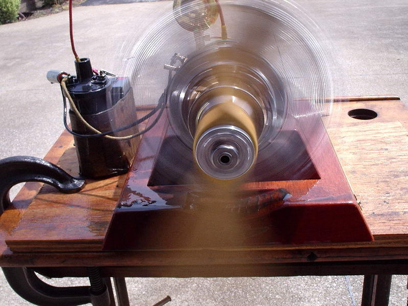
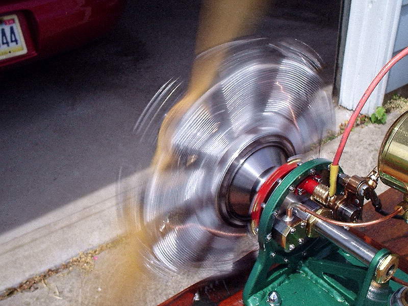
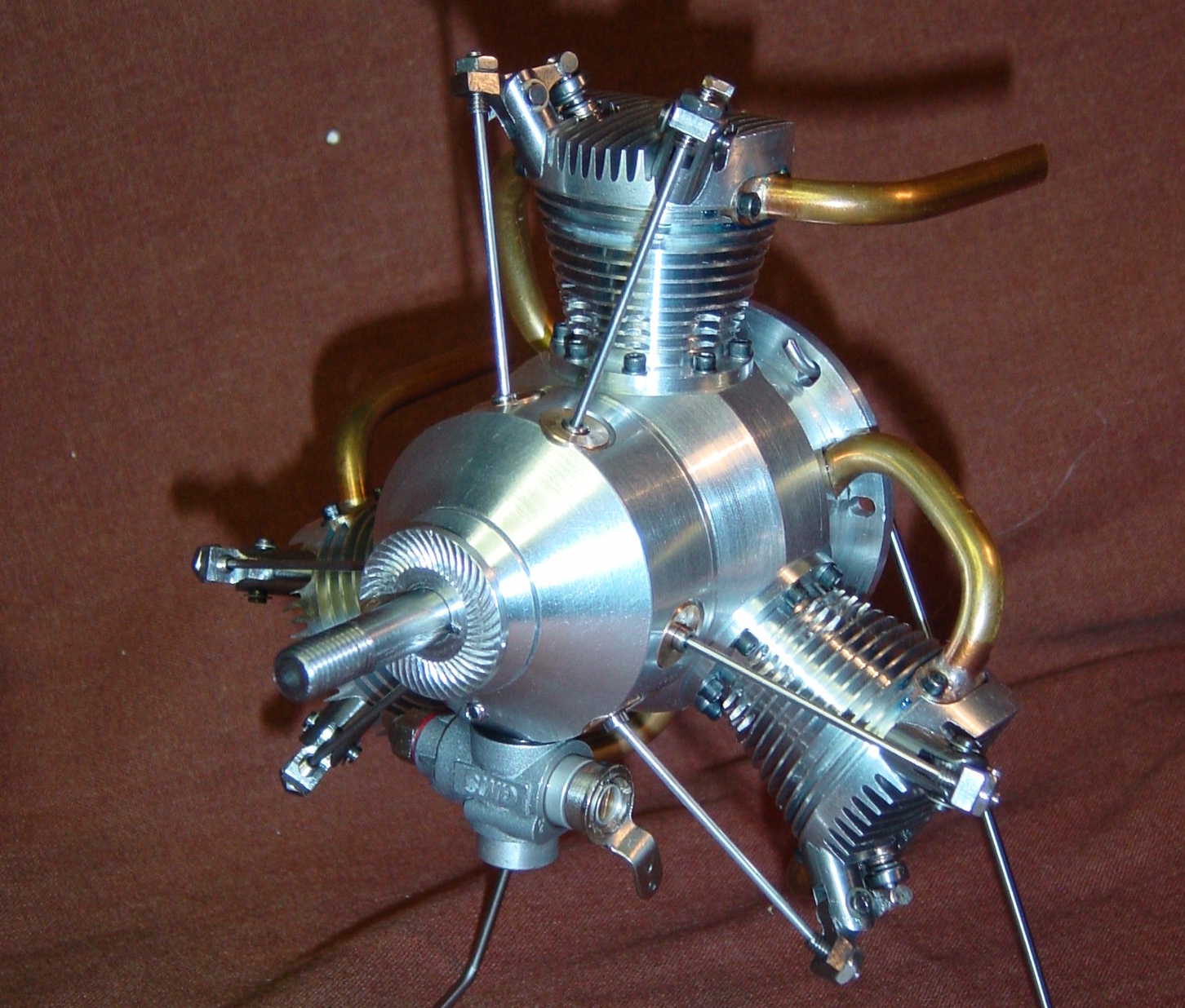
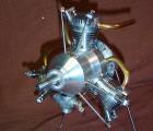
Just before the last issue of MEN was "put to bed", Les Stone sent pictures of his completed Chenery Gnone, saying he needed to motor it in the lathe a bit to free up some tight things. Well that must have been a formality because mere hours after the issue was actually released, Les followed up with the "first run" photo, saying the sound of it running put a smile on his face that would require a skilled surgeon to remove. The prop is a modified Zinger 22x12 and note the automotive coil Les uses for testing his sparkers. This is a very good idea as a nice hot spark is just the ticket when starting a newly made engine for the first time, even ones with only one cylinder!

Having seen other model rotary engines run, I asked Les about the "total loss" oil system and the very efficient oil distribution spray provided by the spinning cylinders with exhausts on top of the heads. Les confirmed that a shower and a change of clothes had been required (twice), but it was worth it every time. Work on the Gnome commenced on March 10, 2011, with the first run on June 30, 2011. All in all, a fantastic effort from a very talented Model Engineer; be proud, Les.
Oh Dear, Oh Dear

IN THE BEGINNING, there were working model engines such as the Atom and Arden .049 gas-ignition engines. So begins a page labeled as "75 Years of Model Engine History" by Eric Henderson, appearing in a supplement to the AMA Magazine called "The First 75 Years". I say again, oh dear, oh dear, oh dear. Apart from ignoring decades of development by model engine pioneers all over the planet, this introduction invents an .049 that never existed. Wonder how long it will be until one is offered on eBay? Several renown model engine historians tried in vein to have this corrected before publication to no avail. If you have a stronger stomach than I, an on line pdf is available here. I don't think I'm being a pedantic curmudgeon (this time) by saying that the AMA does no-one a service by distorting reality like this.
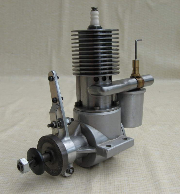
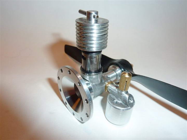
Pep Turns 75

Speaking as we were about 75 year anniversaries, Ian Munro, our prolific New Zealand engine builder friend, noticed from Maurice Poletti's book, Those Incredible Pepperells, that this year would mark the 75 year anniversary of Ira Pepperell's first "Godwit" sparker. To mark the occasion, he decided to build a replica. As we see here, this has been done and Ian's replica turns a 14" wood at 4,500 rpm. May not seem great, but I bet it's fully representative of the original. Ian used high melting point silver solder (not silver braze) on the cylinder and reports that it's holding, so far, as the engine runs much cooler than he expected. The only significant trouble was ignition related, cured finally by a transistor assisted switch. Makes us respect those old model builders from the days before transistors and li-po batteries all the more. Incidentally, Ian cast his own case in a cast iron die. It's efforts like this that leave me feeling inadequate: well done (again), Ian!
Oh wait, hold the presses! I just realized that this engine can't exist since the first model engines were the Atom and Arden .049 which we know originated in the USA in the late 1940's, so there can't have been any model engines made in New Zealand during 1936. I don't know whether to laugh or cry.
MAN .19
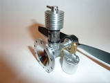
Charlie Stone (Australia) has finished his MAN .19, probably the only one of it's kind to be completed in the past half-century. Charlie's engine is true to Ted Martin's design with the exception of the bearings, propdriver, and piston internals. The prop driver uses a split cone in place of the key-way shown on the plans. I totally agree with this change for several reasons. It's less work, there is a tendency for prop drivers with key-ways to split (guess where), and a friction cone can slip under conditions where the prop suddenly meets an unmovable object while the engine is running. The bearings were provided by Steve Rothwell and have been well proven in his excellent Oliver Tiger replicas. Regarding the piston, Charlie was not happy with the limited gudgeon pin support, so beefed up the pin support area and fitted circlips to retain the floating pin. At the time of writing, the engine has had limited running, late at night in Charlie's shop (he couldn't wait and who can blame him?) He reports that the engine started and re-started easily, like an ED Racer, and even better, the glorious diesel perfume seeped into the house from the shop. I'm with him 100% there, but wonder how well the fumigation went down with The Boss.
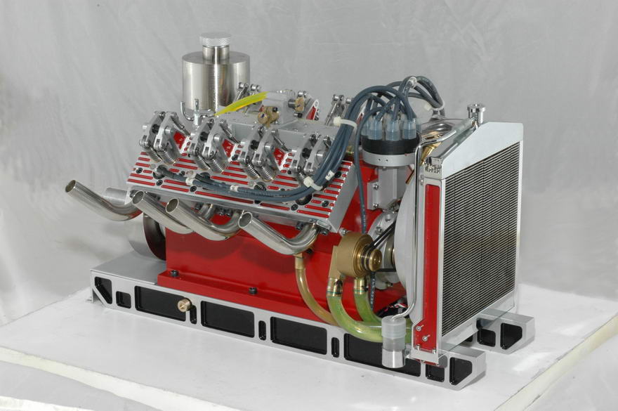
The Sage V-8
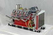
How about that? Dave Sage (Canada) took the late Jerry Howell's water cooled V-4 and extended it a bit while maintaining the unmistakable appeal of the original. Dave says that internally, the crank and cam timing are based on the Chevy V8, for no particular reason other than that's what he decided to do. The result is one I think Jerry would have liked. You can watch a video of the V-8 in action on the Sherline Craftmanship Museum web site, just follow this link. Incidentally, the Museum conducted a group build of the Howell V-4 and you should have a look at that while on the museum site.
Mite
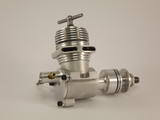
Quick: how many model engines can you name which have used "Mite" for the name? Here's one which only the well versed will identify, namely, the Majesco Mite, and if you want to know a bit more about Majesco, visit the revised Lawerence H Sparey Tribute page. The engine is a repro, not an original—I suspect it's way too good looking for that, even thought it's builder, Rob Jenkins (Sydney, Australia), is a bit disappointed with the finish on his die cast case. The engine has run, though Rob says it's still a bit tight at TDC and some time on a larger prop would not go astray. Note too that there is no compression screw. Like the ED "Penny-slot", the cooling fins press on the contrapiston for adjustment. The side-draft FRV is close to unique, but a rather good idea in a small free-flight engine making me wonder why it was not more widely copied. The details are bore: 0.375:, stroke: 0.400", displacement: 0.724cc (0.044 cuin). The engine was built from Motor Boys plans, and very well built too!
New Books and Magazines This Month
Issue #24 of Model Engine Builder arrived at the end of last month, just too late to talk about, a situation I can now remedy. To me, the outstanding item for this issue is Todd Snouffer's Pip three cylinder four-stroke radial. I reviewed Todd's plans for this engine back in the August 2004 Issue, so there's no more I need say except that it's great that this nice little design is getting wider publication. Also in the issue is editor Mike Rehmus' highly detailed and well illustrated account of building my Humbug .09 on a Sherline tabletop lathe. Another article details making hollow rose cutters to produce miniature bolts. I liked this one too, even though it is more general model engineering than engine building and is the sort of thing we'd normally see in the ME, or HSM. One to you, Mike  .
.
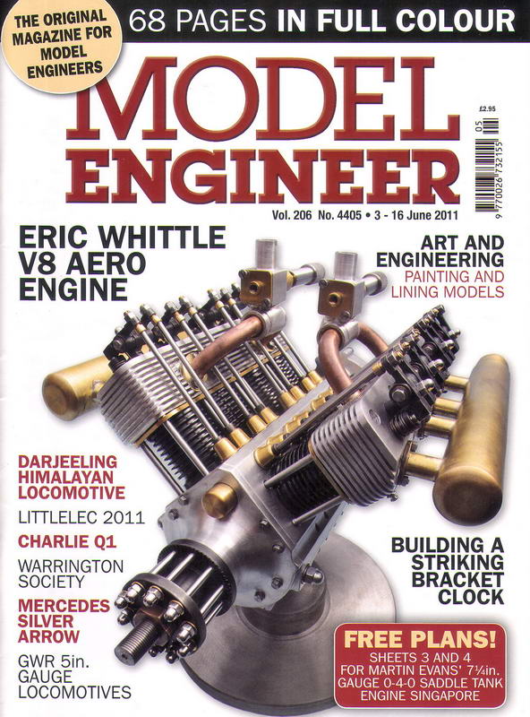
I should also mention recent issues of the Model Engineer, now arriving on my doorstep every two weeks by airmail thanks to the strong Australian economy and power of our Dollar. Commencing with Issue 4405 of 3-16 June 2011, we've been treated to a series on the build of a twice size Whittle V-8 by Mick Knights. Mick explains in the first installment that the original engine is akin to watch making (true) so he decided to double it using a mixture of Imperial and metric (no problem) and make it using a mixture of manual and CNC—still no problem. Where I am having a problem is the unusual presentation: no plans, just descriptions of dimensions! In the part where the faces containing the cylinders, their hold-down bolts, and tappet bushing locations are drilled, Mick gives a table of dimensions from a datum and a "plan" with a section that cannot, is not, does not, represent reality (Issue 4407, p 27).
For a complex part, the use of a datum and distances from it is absolutely the correct way to go. In fact, I constructed one of these while making my Cirrus Mk I. My objection centers on a build series where you have to carefully read the text, noting dimensions on a scratchpad from which to work, or from which to draw the plans that, call me old fashioned, should have been drawn so builders with their own ideas can skip the text and just build the thing. I'll go further. Anyone contemplating a real build of this engine is going to have to draw the missing plans, regardless of how they decide to go about machining it. Yes, drawing good plans is difficult and very, very time consuming regardless of whether you use 2D CAD, 3D parametric CAD, a drawing board, or a paper napkin and a pencil. In the latter case, it is the magazine editor's job to produce drawings of sufficient quality for publication, a task at which the ME of old excelled. I also understand how difficult it has become to obtain material for magazines like the ME, the cost of engaging draftsmen, and the demands on contributors' time when it comes to making fully detailed drawings of a complex thing like a V-8 engine, or any engine for that matter. Still, it will be interesting to see how the series develops as we get into the more complex bits and hope this is not the Shape Of Things To Come.
Engine Of The Month: TOP Engines
You could be forgiven for thinking that what with the Boxer, Hope (five (5) linked pages), OS 29 Twin-stack, Max 15 Diesel, Skyshark, and Strong reviews, our Adrian has a bit of a fixation with Japanese model engines. You could be right, but consider this: if not for Adrian and the preceding list, how many Japanese model engine makers could you name prior to the four-stroke invasion? I'm sure most would get OS and Enya. A few older folk might add Fuji to the list, but that would probably be it for most of us. This month, he lifts the lid on the TOP range. This one I did know about, poorly and inaccurately it turns out, from a 1998 article in Model Engine World. If you didn't read it, prepare to be amazed. If you did, prepare to un-learn some things and learn a lot of others. I especially like the ignition model's timer which is what I've chosen for our teaser image. Having had to render a few timers in CAD and make the bits both fit and work, the simplicity of this one really appeals to me!
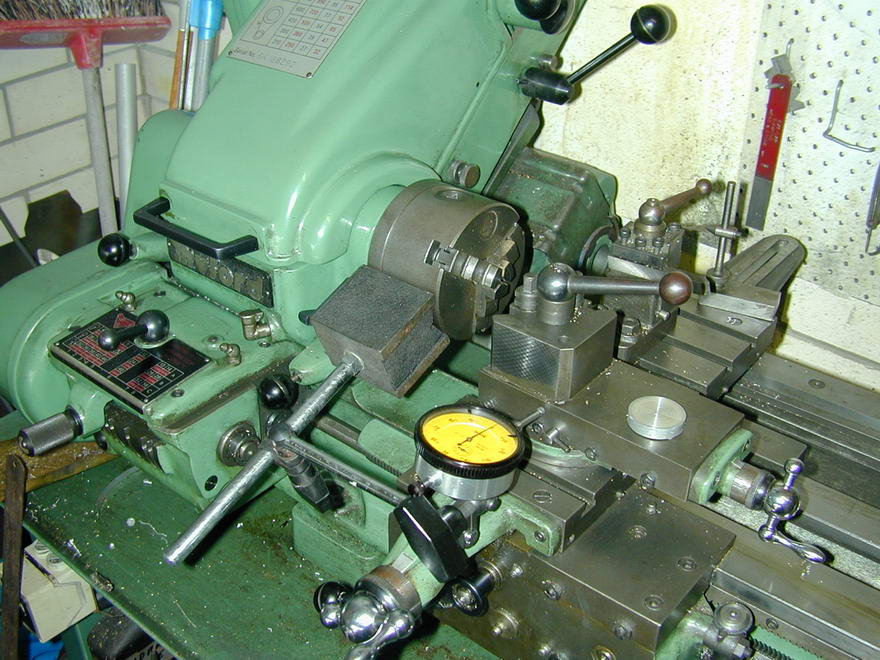
Tech Tip of the Month
Couple of quickies this month. The first comes from Charles Doyle (Dallas, USA) who is an old retired machinist from the old school (always listen to the old guys who learned CNC precision using hands and eyes on manual equipment). Charlie has been enjoying the MEN site and was prompted by last month's mention of the compound slide to pass on a tip on taper turning. Set up your plunger type DTI so you can indicate one side of your compound slide as the lathe carriage is moved. Let's say you want to turn a 5° included angle taper. Halve this and use your scientific calculator to find the tangent of half this angle, 0.0437 in this case. Now set over the compound to about 2.5° using the scale and crank the carriage through exactly one inch. When the DTI shows a difference of 0.044 over the one inch travel, you are on the money. Even better, provided you record the number, you can reproduce the taper any time in the future, or produce mating inside and outside tapers. Of course this method assumes that the sides of the compound slide are parallel to each other and the slide's V-ways, but most will be good enough for government work.
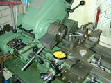
Second: Roughing. Model Engineers are not piece workers, neither do we have to show a profit on the time it takes us to make something, but reducing a piece of 7/8" bar down to near 3/8" diameter for a crankshaft can take a long time if you have to make fine cuts. The work is boring so attention wanders. Bad things have more opportunity to happen when you lose concentration, so "roughing down" quickly is not a bad idea. The question is how much and how best to go about it.

There's no magic here. You can't take a cut deeper than you have the power and rigidity to accommodate. In one revolution, the tool is going to remove metal at a rate governed by the depth of the cut and the distance moved. During this process, the forces on the cutting tool will be trying to move it in the direction of where the metal used to be. Generally, the toolpost, though clamped, can swing around a single pivot point. Also generally, the tool is ahead of this pivot, so if it moves, the arc it describes will make it cut deeper. This deepens the cut so the cutting force increases making the tool move back more, further increasing the depth of cut. Other disciplines call this positive feedback: the more it happens the worse it gets and disaster may be only milliseconds away.

The cure for safer roughing, as shown to me by another old machinist, is to swing the toolpost so the cutting face is at or behind max arc depth imposed by the pivot point. Now if it moves, the depth of cut decreases and the force on the tool decreases. Yes, this means you end up with a sloping shoulder that has to be turned away after the roughing has been done, but that's easy. The advantage is you can safely experiment with extreme depths of cut to find just how much can be taken off in one pass to match the material, state of the tool, cutting lubricant, lathe speed, and feed. I've managed 0.200 depth of cut (0.4" of diameter) into 12L14 leaded steel using HSS tooling on the 3-1/2" center height, 1HP Myford. That's extreme with blue chips and close to flood cooling from a squirt bottle, so my general roughing cut is 0.100" deep, or less if something complains, or a bit more if I'm feeling dangerous. The finish is nothing to be proud of, partially because the tooling was not ground to be used in this position, but that's why it's called "roughing", I guess. Hover your pointer over the photos for some detailed info.
Briefly Noted
This section is intended to alert you to little things that are hard to expand to a full news item, or cunningly wind into the Editorial, but are worthy of note never the less.
- The last page of the EDM saga has been updated with details of an EDM electrolyte that is more user-friendly than household kerosene and is available in Australia at a comparable cost. This information was provided by Martin of Speedex Engineering way back and I really should have added it to the page sooner as a "note to self", if nothing else!
- Frank Bowman has updated his piston ring price list. They are still cheaper and probably better than ones the average lathe owner can make, not to mention all the messing about annealing a ring or two. So if you need a ring for some old engine, contact Frank. Aside: Frank's email name is "ringmaster46". I love that on so many levels.
- We have updates: The AM .049 review which now contains first hand information from an ex-employee that puts to bed once and for all who really made the engine. The Skyshark review has been updated with new model details. The Sparey Tribute Page has been updated too. This is one of the earliest pages on the site and the changes mostly add hyperlinks to things mentioned earlier, which got pages of their own later, if you see what I mean.
- Ben Fleming, whose EDM How-To Book got one of our rave reviews, has nearly finished a follow-on book on a pulse EDM sinker machine. The old design discharges a capacitor to form the plasma, then shorts the power supply through a giant resistor until the mechanics can raise the head to break the short and recharge the C, Pulse circuits remove metal more efficiently and I know a lot of people are waiting on the new machine which includes new mechanics and depth control. More info when Ben sends me a copy (hint, hint ).

 Editorial