Editorial
A couple of thunder storms during the month actually happened in our local water catchments and authorities now say we are at 42% capacity (amazing how many times that number occurs). But the people seem to have lost focus on that, although we seem to have incorporated water saving into our every day reality which has got to be good. But all this is rather overshadowed by the ructions on Wall Street and the ultimate pain they are going to cause everywhere on the planet. One local commentator seemed to sum it up in saying that the American people are now being told to foot the bill for a party they were not invited to. Eventually, I guess that those same people are going to start looking for the guilty and I rather suspect it will get ugly.
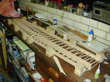 I've had a busy month and as I'll be away for the last week of it at an eResearch conference where I have a paper to present on the world's most boring topic: metadata. So the October MEN page has had to be prepared early and roll-out done in a non-standard way. With luck, on the appropriate day, I'll press a single remote control "button" and the new pages will magically appear. If not, you won't be reading this... But I did find a few spare moments during September to work on the Cardinal. This shot shows the wing in the jig, ready for sheeting and capping. The idea for this type of construction came from PAMPA Stunt News, circa 2000. I'm hooked. The wing went together fast and dead true. It's now finished and the focus has moved to the tail feathers. Still no idea where I'm going to keep the thing when it is assembled. Oh well...
 One last thing before we get down to business: this site exists through sales of the Model Engine News DVD, which have not actually been happening lately. For your dollar (75 of the Australian variety), you get a copy of ALL this website's content, plus eight very complete CAD plan sets, plus another 1,000 pages that will never be made available on-line. Money cheerfully refunded if you are not completely satisfied and in the past three years, I've only had to do that once, and the complainant complained that he'd not actually asked for a refund! Now it may be that every single person on the planet who wants a MEN ONLY DVD now has one, but I rather hope not, so if you've been thinking about it, drop me a line. Payment can be made through PayPal and Australian buyers get a $5 discount.
Construction Features
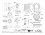
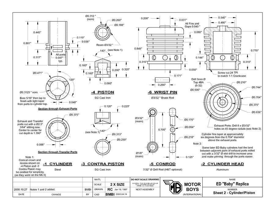
The ED Baby project continues this month with the cylinder, pistons, and conrod. Construction of these, together with the next page of CAD plans can be seen on the ED Baby Reproduction Project, Page 3. The instructions cover finishing the cylinder and pistons to fit, so remember that the split cylinder lap appeared on page 2, last month. The series will conclude next month with the final drawing for the crankshaft and needle valve assembly. Web site log statistics show that this is a popular subject and Roger Schroeder has been busy pouring castings to readers' requests. So if you building one, how about sending a progress photo?

Some web site maintenance during the past month required a change to the index page of the Weaver Construction Log. As well as being upgraded to the "new look" with the sans serif font, there has been some word-smithing and a link added that displays the timing diagram for the engine. The little Weaver is a bit more complex than average due to the unusual transfer arrangement, but it is not beyond the capabilities of a careful worker by any means. A CAD redraw of the plans are available from us at Model Engine News for $15.00 including air postage anywhere in the world.
Castings for both of these engines, including the MBI CAD plans, are available from Roger Schroeder's Classic Model Airplane Engine Construction Kits. Roger has recently updated his catalog, separating out kits that come with instructions from those which contain merely the plans, and those which are bare castings for plans appearing in the MBI Plans Book. The prices have been revised to reflect current postage rates with some items increasing by as much as 0.25c! This is the first price rise in two years and if it does not represent value, I don't know what does. Rogers article on building a model engine that runs has had an update too.
The Motor Boys Book is Out Of Print
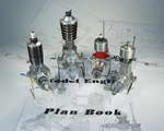
We're sorry to report that the Motor Boys Plans Book mentioned above is no longer available. The stock of copies the AMA held has finally run out and they don't plan to reprint in the near future. But each month, Roger, Tim, or I seem to get at least one request asking how to get the book, or one of the plans in it. So far, we've always found a way, but it's getting hard. The solution is to make it available again in some form. To do this, we need to locate original art work, text copy, and photos. This may take a while as we all have other things that need doing too, but watch this space, and feel free to bug us with requests (sadly, being a bit annoying can be a rather successful project management technique).
More Center Finding with an Edge Finder
Malcolm Beak (UK) has been a long-time supporter of this web site and his work makes frequent appearances in The Engine Gallery. He has also gone as far as acquiring the materials to make his own Vega 30 from the March 2008 MEN Free Plan and found some errors in then plans that have subsequently been corrected. On reading the Tech Tip for August on using and edge finder on circular stock, Malcolm passed on a variation that is worth repeating. With Malcolm's approach, you don't have to measure the workpiece, no know the diameter of your probe tip to three decimal places. But while it could be done without a digital readout (DRO), it would be harder and perhaps a bit error prone. Here's how he does it:
- Let's say we are looking for the centre along the X axis. The work is wound back and forth in the Y axis while advancing the work towards the probe along the X axis.
- When the edge is reached, the probe flicks out, and the DRO zeroed. Back off a few thou and repeat to check for correct zero. This may take two or three goes to get repeatable results.
- Now go to the opposite side and find the edge in the same way, making a mental note of the reading when the edge is found. DON'T zero the DRO.
- Divide this reading by two and advance the work until this reading is shown. Now set the DRO to zero.
- Repeat all the above for the other axis, and with the DRO reading zero for both axies the work is centred under the spindle.
Malcolm states that he uses this method to find the center of material down to 1/4" in diameter. I can see nothing wrong with it except that on the first pair of edges found, the point of contact will be on a slope as it were due to the random starting position in relation to the center. This means that the edge finder will run off faster on one contact point than the other, depending on the slope gradient and direction of rotation. A number of repeats, going more slowly will probably obviate any error though, and the second pair of contacts will be on a diameter, so the problem, if there is one, will not recur. The method I stole from The Machinists' Bedside Reader, by alternating X and Y contacts will not exhibit this characteristic. But I like Malcolm's method and will give it a go.
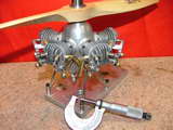
PE Norman: Model Engineer
The name PE Norman should be familiar to all older readers of the Aeromodeller for his pendulum controlled, free-flight scale WWI biplanes and his pioneering efforts to produce some of the very, very early free-flight and single channel R/C ducted fan models. What I did not know until Ken Croft described one of his less successful engine restoration adventures was the PEN was also a model engineer! So click the photo, or follow the link to the PE Norman Sparkie page and prepare to be amazed.
Gallery
As well as the usual EOM feature, there are pictures of another early British diesel in the Engine Finder some new new entries in page 12 of the Gallery this month. These include a very nice SM-5 built by Al Rayborn (USA) from Vernal Engineering castings. The engine is turning 5,100 rpm on glow plug ignition and Al was nice enough to credit the Morton construction series on this web site as giving him the courage to tackle the project. With an M-5 under his belt, I'd say there is now no project he can't tackle!
New Books and Magazines This Month

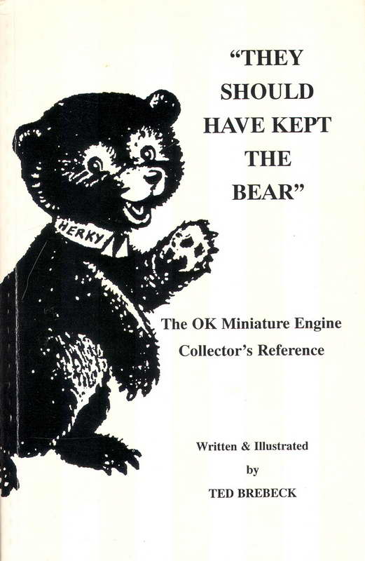
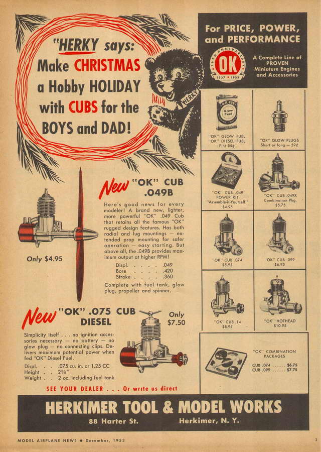
This is hardly a new book, but the review is appropriate for reasons that will become clear soon. The title just about says it all: They Should Have Kept the Bear, by Theodore R Brebeck, OK Engines, Mohawk NY, 1995, ISBN 0-9628337-1-1, 72 pages, soft-bound, small format. The author is the grandson of Charles Brebeck senior, company founder and designer of the OK and Mohawk range of engines that were produced between 1939 and 1964. His book was written to present the "factory" side of the OK story following articles appearing in the modeling and engine collecting press which he felt were inaccurate and misleading. When approached, the authors and editors involved were unwilling to listen or to publish his first-hand recollections, leading to this self published booklet. Sadly (although perhaps wisely) he does not cite these articles, but some are not hard to find. The content of his book makes for a definite "You Decide" experience.
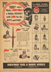 "Herky" was the bear cub mascot icon used by the Herkimer Tools & Model Works in their advertising and promotional material (note connection to their line of CUB—small—engines). He was dropped by company founder, Charles Brebeck Senior who said "HERKY is jerky", and believed that the image was undignified (p43). His swansong was this advertisement in the December, 1953 issue of Model Airplane News and the subject was our engine of the month: the OK "shock absorbing" diesels. Obviously lamenting Herky's demise, Ted observes that today, stuffed animals and animated characters support million dollar businesses; he sees dropping Herky as the biggest mistake in OK's history and the beginning of the end for the dynasty. He may well be right about this, though having the ammunition that would have shot down the law suite filed against RTF maker, Comet, who was their biggest customer, by AMF/Wen-Mac over recoil starter copyright infringement, and failing to fire it must come a close second.
 Regular readers will know that I like to give a synopsis of books reviewed. That is difficult in this case as there is so much in the way of fascinating little snippets in Ted's book that I don't know where to start. The structure tries to present the story chronologically, drawing a dividing line at World War II and presenting some insights into why some model engine manufacturers seemed to be able to continue production during this period, while others could not. Separate tables list the engine types produced before and after the war with the release date and some identification features. The text contains no illustrations, but three photographs are included that show "OK" and "OK Cub" engines, with the drone engines the company produced during the war—both their own, and under government contract and license to the Righter Motor Co.
The dates for company name and ownership changes are given and the author states that he has available allmost all the advertising, development, corporate and production records for the Herkimer Tool and Model Works. Any information that could not be validated from three separate sources was omitted. Later he notes that certain unscrupulous collectors removed parts and invented models from these which never existed. These were sold to unsuspecting collectors. He writes that material he provided to a magazine editor was changed to support that editor's beliefs before publication, leading to even more confusion. So what should we believe? There is an underlying bitterness in this text which is understandable to some degree. But there is no supporting evidence, not even references to documents; just assertions. Realistically, providing all the supporting evidence would be difficult, expensive, and probably not all that interesting to the general reader, so this complaint may just be my personal bias in action.
My feeling is that the author is being honest, although being third generation, his recollections and records research may represent a colored viewpoint. That said, there are things to amuse and astound on almost every page, like Charles Brebeck junior's obsessive experiments which showed that a Cox engine ran better with an OK glow head, and an OK engine ran better on Cox fuel. I remember being highly entertained by this book when I acquired and read it over ten years ago. I was equally entertained re-reading it for this review (the much overworked blessing of advancing years  ). So Four Stars
  with the one taken off for not backing up statements which are at odds with other accounts with hard evidence. A quick search at the time I wrote this review indicated that new and used copies were available from Amazon Resellers at prices ranging from US$58 to $125.00! Ouch.
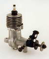
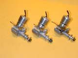
Engine Of The Month: The OK Cub Diesels
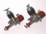
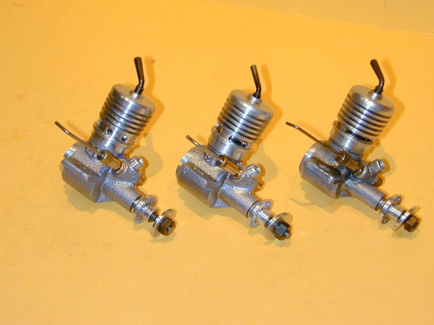
US engine makers did not really get into diesels, although a few of the high volume manufacturers did give them a try, specifically McCoy and Herkemier (OK). Both chose to use an O ring to seal the contra-piston rather than the lapped cast-iron favored in other countries. This came in for some criticism as "lacking feel", even though it apparently worked quite well—perhaps a case of Not Invented Here syndrome in action. The OK diesels also featured a unique "energy absorbing" design feature. Adrian Duncan hsa dug into his collection to provide the history of the OK diesels, aided by the MEN Library, which also provides the related Book of the Month. As usual, click the thumbnail picture, or the many other ways provided to read the OK Diesel Story.
Tech Tip of the Month
Commercial model aero engines generally have hardened components. This process is applied to things like crankshafts and cylinder liners to reduce wear and increase crash resistance. Most model engine builders get by with "soft" components. Wear will be acceptable for occasional or sport use; crash damage is another matter entirely, especially for crankshafts where even a stubbed prop can result in a bend to the delicate, threaded section of the crankshaft where it emerges from the strong reinforcement of the crankcase bushing. The most practical answer is to use a separate screw-in stud cut from a hardened cap head screw. Even if bent, a stud is easily replaced and damage will almost never translate to the relatively soft crankshaft.
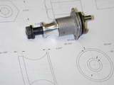
This is a good solution, but even for small engines it suffers from an annoying problem that increases with size. In commercial engines, the finely finished "journal" of the crankshaft may not be much larger in diameter than the threaded, protruding section. And the latter will have an unthreaded portion to provide a close fit in the drilled propeller, accurately centering it and minimizing vibration—provided the prop itself is well balanced. If we use a threaded stud, there will be some slop in the "standard" drilled prop hub. Worse, in order to provide a reasonable wall thickness for the drilled and threaded hole in the 'shaft for the stud, we may be forced to employ a stud size somewhat smaller than the diameter of the hole found in the propeller we want to use. A bush can be turned to fit the prop which effectively reduces the hole size while maintaining concentricity (extra work), but there will be some slop in the screw thread that prevents it all giving a good sense of repeatability in larger sizes. Fortunately there are at least two solutions to this problem.
The first is to turn a protruding, centering, stub integral with the propdrive washer that has a diameter equal, or greater than the hole size for the standard propellers you expect to use. The stud passes through this and if it is a bit wobbly in the threaded shaft, it does not matter as long as the stub, drivewasher, and shaft are reasonably concentric. The down-side is the stub will make the task of plunge knurling the prop drive washer a bit more difficult. If the geometry requires that the stub be larger than the standard prop hole, we are almost back where we started as the prop now has to be counter bored with the possibility—some would say inevitability—of introducing a balance problem through eccentricity. A number of early British commercial engines had this "feature" and I've watched modelers open out the prop hole with the tang of a file in order to get it to fit over the drive stub; real precision work, that!
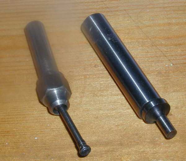
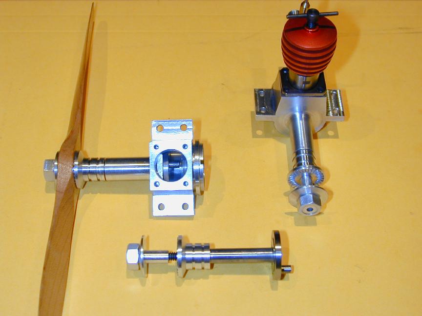
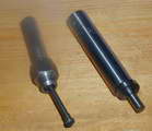
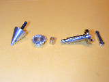
The second way is to draw on the way Dooling, McCoy, ETA, Oliver, and other makers of high performance racing engines used to extend the length of their engines so that they could use a short, torsionally rigid crankshafts, but still provide an engine profile that could be streamlined into an efficient, attractive, fully cowled nose. This uses a long prop drive washer, counter bored for a shouldered nut which is turned to a close sliding fit in the counterbore. This shoulder is also a close fit in the prop resulting in the latter being accurately centered. The stud size and "slop" is thus rather immaterial.
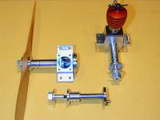
In this photo, a small diameter 6-32 stud threads into an aluminum prop nut with a 3/16" diameter extension; this being a common size for commercial 7" diameter plastic and wooden propellers. The "nut" extends through the prop and into a 3/16" counter-bore in the prop drive washer, thus centering the prop. The resulting assembly is quite rigid, somewhat reducing the crash-resistance of the simple stud design, but even so, it is more able to withstand hard landing and outright crashes than a "soft", one-piece steel crankshaft with an integral 3/16" threaded front section.
 Construction Features
 Editorial