Editorial
This month, Model Engine News lives up to its name by presenting lots of, well, News! There are 11 items in the special features, but the most exciting news item, to me anyway, is the announcement from the Mojave desert, received via the web from Aero-News Network. At 0813 PDT on September 29, 2004, pilot-astronaut Mike Melvill has flown Bert Rutan's SpaceShipOne to a height of 337,500 feet in the first of two flights required to claim the $10 million Ansari X-Prize. That's almost 2 miles higher than the 62 statute miles required to qualify. The Scaled Composits team, backed by Microsoft co-founder, Paul Allen, must now make a second flight within two weeks to secure first place. This achievement totally failed to make the Australian news this morning, which contained as usual, nothing more than bleating, egotistical, electioneering politicians. Makes me rather sad, but that's life I guess.
The site had the standard 8,000 odd hits for September, and I got nothing accomplished in the shop. But I did manage to repair my Gieseke Nobler and fly it to a first place win in a local control line stunt comp—even if the required maneuver sequence was a simplified old-time pattern. That was a buzz, resulting in yet another nice but functionally useless trophy. Next month, the Feeney runs, promise!
Model Engine Builder

The big item for the month is the news that a successor to Strictly Internal Combustion is in the planning stages. Husband and wife team, Mike and Toni Rehmus are evaluating the feasibility of launching Model Engine Builder, a magazine that would cater for model engine builders at all experience levels. Mike suggests that MEB would be quarterly in its first year, ultimately going bi-monthly like SIC of old. If the bones fall right, and all the portents are good, publication could commence as soon as spring 2005 (in northern hemisphere). This is a major undertaking requiring significant initial and ongoing support from us in the form of subscriptions and content—not to mention hard cash from Mike and Toni. Certainly I'm happy to pledge both. I must stress that at the time of writing (mid September 2004), MEB is not yet committed to go ahead, nor are they accepting subscriptions. But I urge you to visit the Model Engine Builder website, and if you are able and earnest, email Mike and Toni to express your support and maybe have some input into what you'd like to see in a model engine builder's magazine. And I'd appreciate it if you mention Model Engine News when contacting them so we can gauge just how widely read this site is!
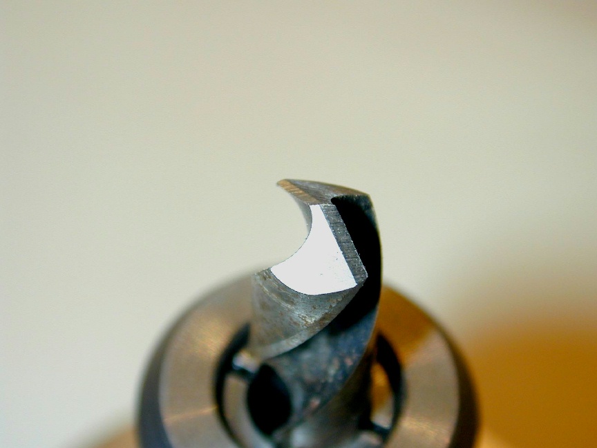
CNC and Four Facet Drills
Late last year I posted a page that described the fixtures I'd built from a Model Engineer article to simplify four-facet drill sharpening in the Quorn. Shortly after, I received a nice email from Steve Scampini saying this sort of thing intrigued him too and that he had an idea for using a CNC mill to arrive at the same end. Steve has now completed his sharpener and done a real nice job of presenting his design on-line. Be sure to visit Steve's web site and see how he tackled the problem.
Twins
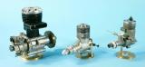
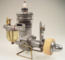
Did I ever mention my incurable twin fetish? Ok, probably only six times in the last half-hour... At model sizes, they are tricky and intricate to make, they can be hard to get to run right, and they simply don't give the performance of a single at the same capacity. But still, there is a magic to them which to me, outweighs all these niggardly little imperfections. And where is all this leading you might ask? Last month, I received an email from a reader who had tracked down my Watzit page while trying to identify a set of castings that had come to him with his lathe. There are some similarities between his castings and the Wasp Twin pictured here (like two opposed cylinders  ), but it's not one of those, and it has us—the Motor Boys—stumped. Unfortunately, while there are castings, there are no plans. Hence the somewhat frustrated owner is willing to part with a set of castings to anyone who can furnish a set of plans. So check out the pictures of the castings on the updated Watzit page, and email me here if you can shed any light on it.
Satra/Morton M1
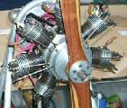
Here's yet another engine buily by the prolific Les Stone whose Pepperell 7/16 replica appeared here last month. This time it's a "Morton" M1 built from the Vernal Engineering kit produced by Bruce Stara. It should go without saying that there never was a single cylinder Morton M1 (although Morton did make a .29 single cylinder prototype). The Vernal M1 is an adaptation of one of Dennis Fadden's variations on the Morton theme. It uses Bruce's M5 head/piston investment castings, and his M5 carby hanging off a custom elbow. The crankcase, shaft and gearbox are designed to work with these components. A kit of all cast and not easily machined parts for the M1 (like the gears and cams) can be ordered from Bruce at around US$175. Individual components are also available for those who'd like to save a dollar by machining some of their own bits, although the kit price represents a 33% saving on the single item price total (please check before ordering as my price list is a bit old). After looking at Les' photo, I'm seriously thinking that this will be an excellent way to test and debug all the M5 cylinders separately before trying them collectively in the M5 radials.
Pepp of the Month
Seems like we can't let a month go by without mentioning the Pepperell diesels. This one has been with the current owner since he bought it slightly second hand in 1948 while finishing high-school in Wellington, New Zealand (the home of the Pepps). The visible deviations from a "standard" Pepperell seven-sixteenths on the engine (squared-off mounting flange and conventional NVA) my correspondent confesses to having instigated—which is the sort of things young lads did, and still do, to get a desired result—usually more speed! However, it's the more subtle things on this example that grab me: The attractively rounded rear face to the prop driver, the two holes in the top of the cooling muff for a pin-spanner, and the delicate nature of the top fins that leads to them being easily bent, just as described in the Pepperell book.
 The Pepp madness is spreading too. Eric Offen is close to completing a crankcase die as seen here. Every Pepperell crankcase we've seen now (all three of them) indicates that George and Ira Pepperell carefully filed away all die parting lines from their cases and polished them to a bright finish, perhaps by hand, perhaps by tumbling, and presumably before machining. So someday soon-ish we'll be in a position to start a new Motor Boys project (or two, Eric is working on an MS 1.2 die too!)
Fancy a Challenge?
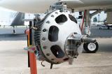
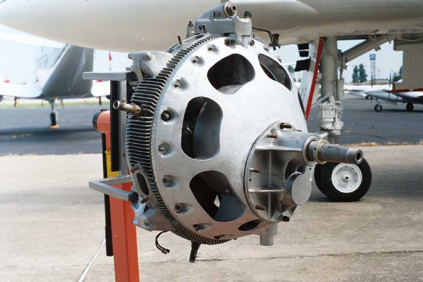
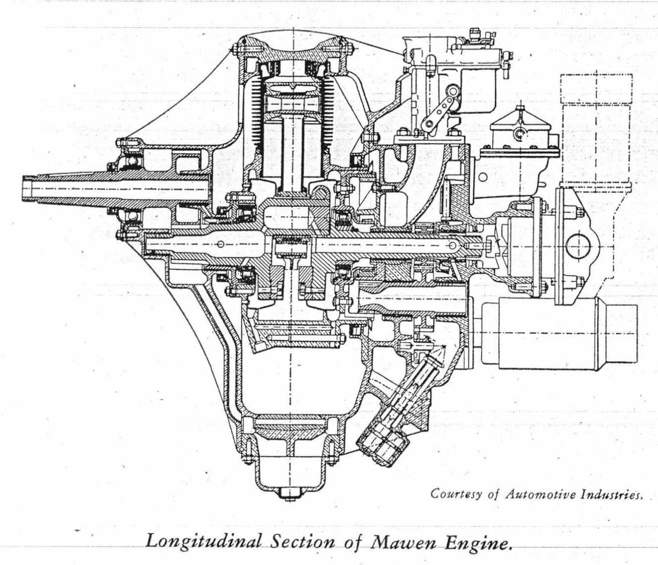
Research into other things in the past month or so has led to an unusual design known as the "Mawen". The concept originated in France in the 1930's and after you read how it works, you'll probably agree that the design could only originate in France (ok, maybe the Brits as well...) Later development took place in the US at the University of Kentucky for the Mawen Motor Corporation of New York City, with backing of French automobile manufacturer EEC Mathis, and Swedish industrialist Axel Wenner-Gren (founder of Electrolux).
The design is termed a "differential rotary". Like most radial engines, the crankshaft carries a master/slave rod arrangement, with conventional, ringed pistons. However, the air-cooled cylinder bank (7 cylinders in this case) is free to spin on the crankshaft. But unlike a WW I rotary, the crankshaft rotates too and the cylinders are geared to turn in the opposite direction at 1/7 crank speed (reciprocal of the number of cylinders).
Now it gets really unusual: the cylinders are open topped. Surrounding them is a fixed ring in which are placed alternating inlet port, spark plug, and exhaust port openings. There are four sets of these (port sets = [# of cylinders + 1] / 2). Plates at the front and rear of this ring provide bearings for the shaft, accessory attachments, engine mounting points, etc.
The engine operates on the four-stroke principal (inlet, compression, power, exhaust) by sequentially presenting the open top cylinders to the relevant areas of the head-ring. So there are eight piston strokes (four complete cycles) per piston, per cylinder bank revolution. Hence 28 power strokes per bank rev, or four per shaft rev, or eight per two crank revolutions. A conventional radial would have only seven power strokes per two crankshaft rotations. The extra bang occurs because the crankshaft is "gaining" on the relative position of the block by 1/7 of a rev per rev (and the reason why the crank/block gearing ratio is related to of the number of cylinders). That's half a "cycle", so in two crank revs, we get an extra power stroke out of a cylinder. Which cylinder it is providing the extra urge is constantly precessing, so every one gets a turn. But are we really gaining anything? I'm not sure. It will take a polar plot and some head scratching to determine this. The engine was apparently high-revving, so the crankshaft was geared to the prop shaft, giving a reduction of about 1.6:1 at the prop.

Being essentially a form of sleeve valve engine, a number of moving parts are eliminated (cam ring and gearing, tappets, rockers, pushrods, poppet valves). But a few new ones are introduced, as are some design problems associated with sealing the open top cylinders to achieve compression, delivering and scavenging oil, etc, etc. There's some extra gyroscopic forces to contend with and keeping the sleeve ring circular and in contact with the cylinder tops with the all the alternating cold and hot spots around its periphery, while keeping friction losses and weight down presents more than the odd design challenge, or two.
Development of the Mawen was undertaken at the University of Kentucky up until around 1942. Perhaps it was the entry of the US into WW II, or maybe it was all the inherent problems, but the engine sank from view around this time. Sometime later, the engine pictured here was sold to a farmer who wanted the stand it was on rather than the engine itself. Fortunately, it was later rescued by the Aviation Museum of Kentucky which opened in 1995 with the annual reunion of Doolittle's Raiders as special guests. The engine now sits on a new stand as pictured above with the museum's fine, newly restored F4S Phantom seen in the background. Apart from some patents filed by Prof. Andre J Meyer of the University of Kentucky on behalf of the Mawen Motor Corporation (US Patent 2,181,705, and others), information on the Mawen engine and company is hard to find. Dennis Sparks at the University of Kentucky is currently researching the history of this engine to go with the museum's display. If you have anything at all to add to the history of the engine, company, or Prof. Meyer's work, we'd be most pleased to hear about it. Now who is going to be the first to make a scale, working model of the Mawen?!
More on Barry Jordan's Models
Last month, mention was made of Barry Jordan's machine tool models and their impending auction. Since then, I've stumbled over the Internet Craftsmanship Museum (sponsored by Sherline Products), which has a page dedicated to Barry J Jordan that is worth a look. The site also has an IC page featuring pages dedicated to model engine pioneers like Dick McCoy, Shigeo Ogawa (Mr OS), Duke Fox, etc. The page is sponsored by Motor Boy Tim Dannels, editor of The Engine Collectors Journal.
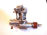
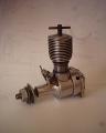
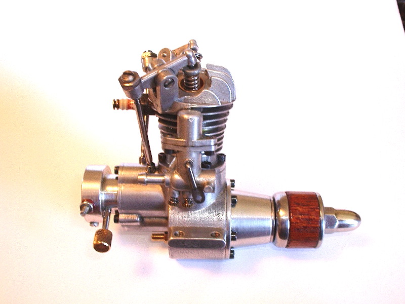
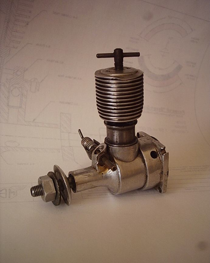
PB 0.33 Update

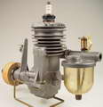
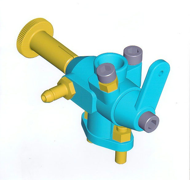
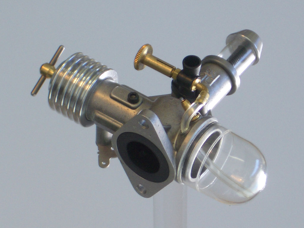
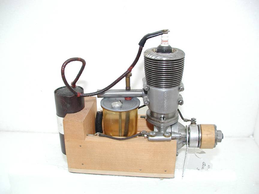
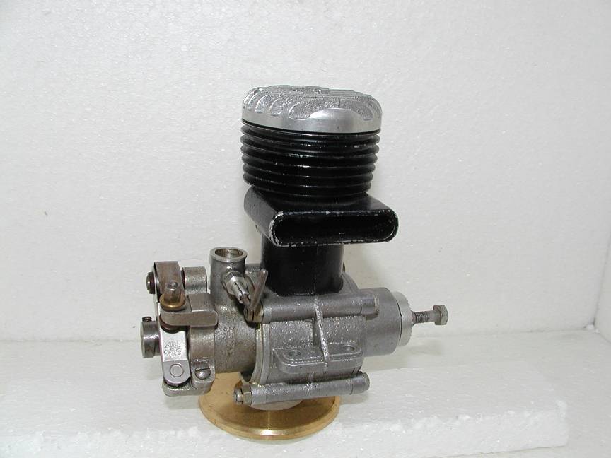
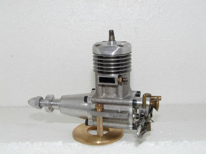
An email from Peter Burford says that he's finished development of an R/C carburator for his magnificent little 0.33cc diesel. His website includes a picture of the injection molding die for the body. At the left is a 3D CAD rendering of the carb (by Peter) and, to refresh your memory, a photo of the engine it will fit onto. The PB Website has also been updated to include a pdf version of the engine review that appeared in Australian Airborne magazine (fully authorized) by resident Airborne Engin-ear, Brian Winch. A future website update will add some appropriate model designs for the engine. I've suggested Bert Streigler's Pumpkin Seed—a fat little R/C biplane from 1964, originally powered by a diesel-ized Cox 020 Bert made—provided we can sort out copyright issues with RCM&E where it was published. Ordering information for the engine, and the R/C throttle when it becomes available, will be on Peter's website, or you can email him at [email protected]. My visit to his shop can be revisited on the PB page (which I really must index through the left-hand navigation panel, someday).
Miguel de Rancougne Auction #2
Earlier this year, Ron Moulton generously provided pictures and text for the late Miguel deRancougne's fabulous engine collection, and the Christies Auction that was as much a model engine exposition as it was an auction. At the time, Ron mentioned that although the auction realized almost half a million pounds, there were more items yet to be offered, including the Bugl team race diesel (pictured below) that could not be located at the time of the Christies event. An email from Ron this month provides the details of the final installment in the dispersal of Miguel's collection; over to Ron:
Special Auction Services of Kennetholme, Midgham near Reading in Berkshire will be including 100 Lots from the remaining part of the Miguel de Rancougne Collection in their sale of Toys & Models for the Collector on 16th and 17th October. The first part of the sale on the Saturday includes Gauge 1 live steam Locomotives & Carriages, including complete sets from the late David Jenkinson's property, plus numerous diecast collectibles . The de Rancougne estate which incorporates rare petrol ignition engines, tether racing cars and off-road radio controlled cars will be sold on the Sunday. Viewing starts from 9am on each day until 11.45am at the saleroom which can be found adjacent to the Berkshire Arms Hotel on the A4 main road 8 miles west of Junction12 on the M4/A4.
A Catalogue is available, price £10 from the Auctioneers at S.A.S, Midgham, Reading RG7 5UX, Phone 0118 9712949 , Fax 0118 9712420 or via details on the Website at www.invaluable.com.
Miguel de Rancougne's property will be of special interest to all collectors of vintage model aero and racing car engines of which there are 30 examples ranging from the rare Gerald Smith "Wizard", an original Ohlsson taper fin "Gold Seal" , Hallam and Fisher ignition engines to the diesels by Paul Bugl, Delmo, Maraget and Barbini. Approximately thirty cars cover the classic period of post-war tethered racing to more recent R/C running both for speed and off-road. Remaining Lots will appeal to model makers as they comprise boxes of discarded components typical of any serious enthusiast's workshop. Generally separated into groups of associated interest are sets of ignition and glow plugs, wheels, castings, tanks, engine components and general material worthy of salvage. To be auctioned from 12am on the 17th October, the Rancougne Collection can be viewed on both days of the auction from 9am.
GEARS 2004
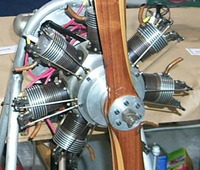
Back in the March 2004 Model Engine News page, I mentioned that the Gas Engine Antique Reproduction Society (GEARS for short) would be holding their first exhibition at the Portland, OR Kilever Armory in late September. This happened on schedule and by all reports, while smaller than the PRIME shows, it met expectations and was enjoyed by all. Carl Carlsen has recorded many of the exhibits and has put together a nice montage of GEAR 2004 photos on-line for the enjoyment of those of us who couldn't make the scene. The engine pictured here is a double size "Jemma", scaled up from the plans that appeared in SIC. Carls says the engine was both displayed and run at the show. All you folks fortunate enough to live in the beautiful Pacific Northwest should consider making next year's event even better.
New Books and Magazines This Month
This month I'm going to recommend two books that are will help those designing their own engines from scratch. One is new, the other is out of print, but not too hard to locate on the web from places like Advanced Book Exchange (ABE). Neither go very deeply into theory, gas-flow considerations, or advanced math, so are well suited to the amateur home-shop designer who wants to do a bit better than eye-ball engineering.
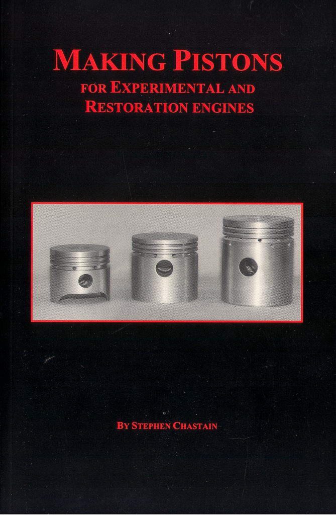
 First we have Stephen Chastain's little 64 page booklet on making pistons, appropriately titled, Making Pistons for Experimental and Restoration Engines, ISBN 0-9702203-4-0, and I suspect, self-published. Steve Chastain is no beginner to the topic of foundry work. A short search on his name will dig up a stack of reviews of his books on the subject, and Metalweb News has a page authored by him titled You Can Cast Iron. The piston book is new and is not a "model engine" book per se, although a model engine designer will find it useful. Its intended audience are folk restoring full-size engines who need the odd piston or two that haven't been made for the past 50 years or so. Steve describes how to make the pattern, core box and machining fixtures to bring old clunkers back to life.
So why am I recommending this book to model engine designers? The reason is that almost half the book is devoted to piston design factors that are equally applicable to models, particularly those larger ones with ringed, aluminum pistons. The author's approach is very empirical, with just enough tables and math to back it up if your are really interested in seeing why. The first volume of Strictly Internal Combustion magazine contained a number of articles on empirical design by a number of authors (Bob Paule, Richard Condon, Bruce Stara, etc) and the numbers there agree with the numbers in Making Pistons. The book suggests using pre-made compression and oil rings, but does make brief mention of how a ring could be annealed to the correct gap that looks rather familiar. Sure 'nuff, the bibliography in the back credits SIC and George Trimble for his seminal work, Design and Fabrication of Piston Rings. Perhaps not so surprisingly, eight of the 12 references cited are more than 40 years old.
-oOo-
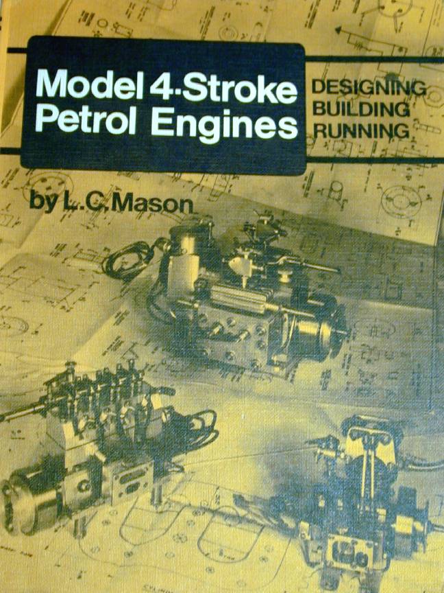
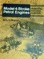 The second book for this month, by the late LC Mason, is Model Four Stroke Petrol Engines: Designing - Building - Running, first published in 1976 by Model and Allied Publications, England, ISBN 0-85242-431-0. I read in an old Camden catalogue that MAP did a special print run for the US market changing only the word "Petrol" in the title to "Gasoline", but the customer went out of business before the order could be delivered. Copies of that are available too (email me for the location of one currently available for sale). Len Mason wrote mostly in the Model Engineer, although I believe his construction series for the George H Thomas Pillar Tool appeared in the US magazine, Home Shop Machinist (entirely appropriate as the tool had been serialized in the Model Engineer by GHT himself in the first place).
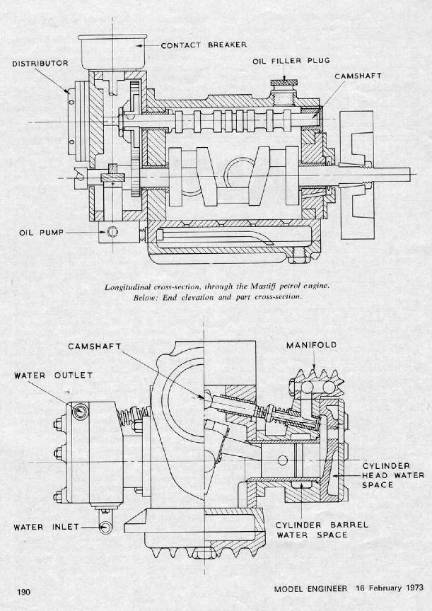
You may recognize Mason's name as the designer of the Mastiff, a four-cylinder, water-cooled, side-valve, four-stroke, boxer. This engine (which appears in the rear of the photograph on the cover of the book) was serialized in the ME. It started in issue 3495 of February 16, 1976 and ran forever. Other articles by Mason appearing in the ME detailed his experiments making miniature spark plugs, and statically balancing crankshafts. The M4SPE book reprints the static balance articles and some parts of the spark-plug article, but appears mostly to be previously unpublished material.
His style is very light on formulae and tends towards "word-pictures" rather than illustrations, though there are a reasonable number of photographs and line drawings. Many of these have been drawn from the Model Engineer which is unsurprising considering that the book is from the same publisher. In 11 chapters he covers just about everything from first steps laying out the design on paper, to fault-finding the finished creation. A lot of the book appears to be common-sense, though it's remarkable how much common-sense isn't until you see it written down.
He gives two approaches to design. One is to begin with a front elevation of the crankshaft, then proceed upwards to the cylinder head. The other uses the side elevation and grows from the cylinder head downwards. His contention is that the crank-centric view is better suited to single cylinder engines, while the side-view downwards is better for multi-cylinder engines. The reasoning being that stating with the crank of a multi-cylinder engine can leave you with problems fitting everything in by the time you get to the cylinder head, so requiring the crank to be revised. Not such a problem in these days of CAD, but valid never the less.
Some of the material he presents would be applicable to two-stroke designs, but it is in the area of valve design and cams that he provides the best empirical tips I've seen, with only as much math as is absolutely necessary (and nothing more advanced than what you can do on a pocket calculator). And I like his first entry in the FAULT/PROBABLE CAUSE table: Fault: "Engine will not start". Cause: "Almost anything!" Rings a bell with me . So, an oldie and out of print, but one worth chasing down, or finding with an inter-library loan.
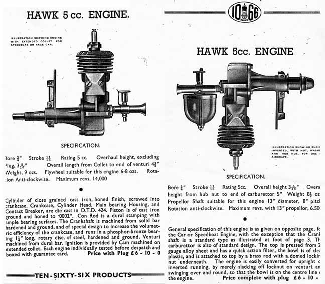
Engine Of The Month: 1066 And All That
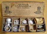
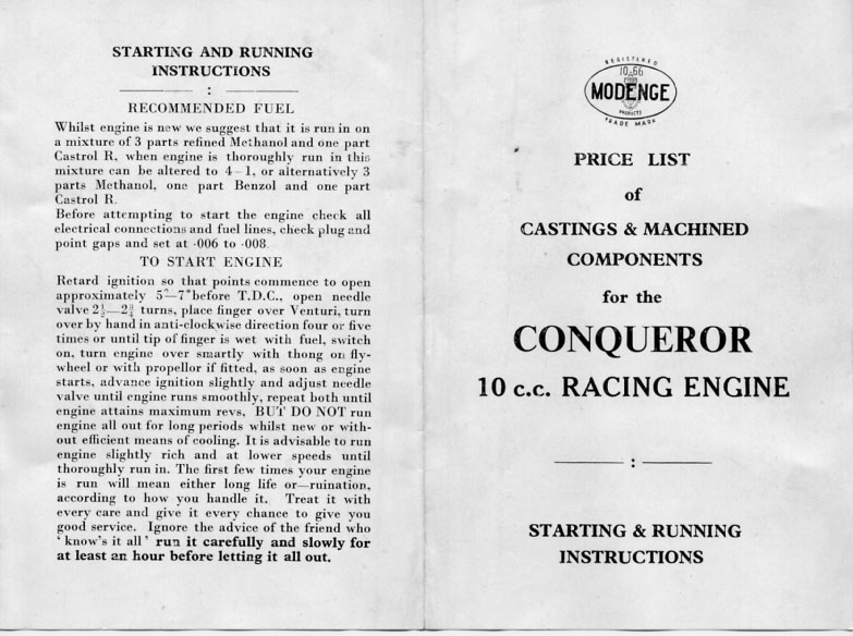
How's this for a lucky find? A complete "Conqueror" kit, in original box and packing. As Ken Croft says, absolutely as it left the factory and far too good to actually work on, complete right down to the little paper packet of screws (top right corner) with "MODENG" clearly visible on it. The designer's name was Hastings and if you can't now figure out why the company name is "MODENG 1066", we can only assume you slept through history class. 1066 Products of Worchester, England, produced un-machined kits, machined kits, and completed engines in the period immediately following World War II. The models are listed below, although there is rumored to have been a 10cc Falcon prototype as well:
- Falcon 5cc side-port
- Hawk 5cc RRV with screw-in cast-iron cylinder
- Arrow 5cc RRV with separate aluminum cylinder attached by 4 screws
- Conqueror 10cc RRV mono-block case
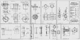
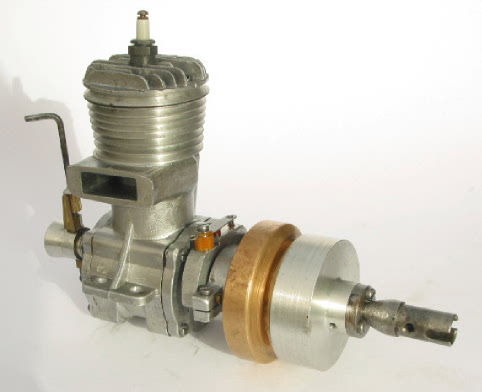
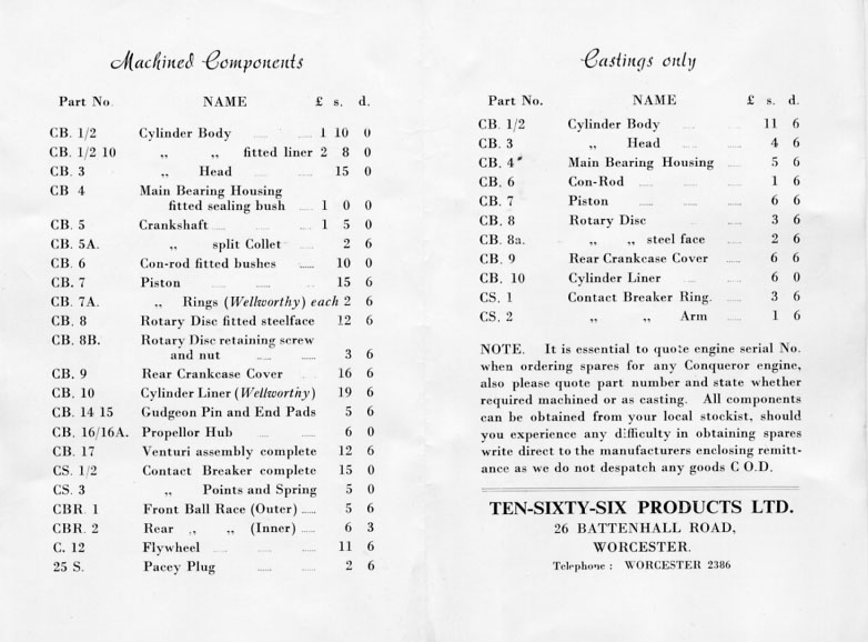
Above is a completed Conqueror built as a car engine by Mr David Owen. The intended purpose of the engine was tether car and hydroplane racing and it is build per the plans, complete with a centrifugal clutch. How that operated without a throttle is anyone's guess. It may have been intended to function as a safety device should the engine suffer a sudden hydro-lock due to a capsize, but we can't be sure. The price list for machined and un-machined parts appear beside it. The sheet also contains the running instructions which are a little unusual in specifying a methanol/castor mix for a spark ignition engine, but perhaps not for a "racing" engine. If ever an engine deserved to be nick-named "Norman", this is it!
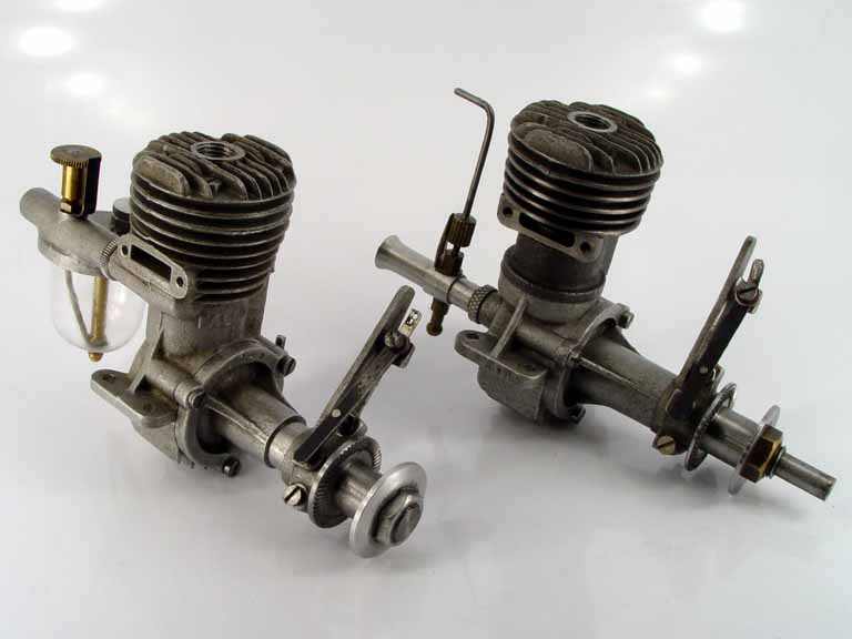
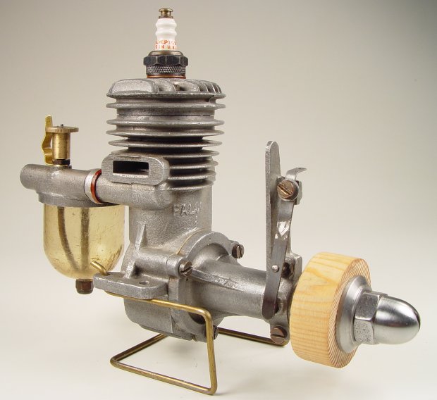
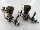 Here, on the left, we see the 5cc side-port Falcon. The engine on the right we assert to be the 5cc RRV Hawk with the screw-in cast-iron cylinder assembly (both engines in Ken Croft's collection). I can't help feeling that the designs have a Westbury-air to them. The Hawk even has an un-threaded crankshaft with a draw-in split collect hub, just like the Atom Minor mentioned last month. The well known model engine reference book, Clanford's A-Z of Model Engines, is known to have numerous errors. One of them is mistakenly calling the Hawk an Arrow. For doubters, compare the alleged "Arrow" picture on page 192 of Clanford's with the engine on the right in this photo. They are clearly the same, so will the real Arrow now please stand up?
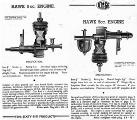 For doubters, as evidence we present Exhibits A and B: respectively, the Arrow drawing, and an advertisement for the Hawk. Exhibit A is clearly labeled Arrow and shows a cylinder assembly secured by four screws. The drawing of the Hawk in the 1066 products advertisement is less clear regarding the method of cylinder mounting, but the text clearly states "Cylinder of close grained cast iron, honed finish, screwed into crankcase.". This description perfectly identifies the engine appearing in the picture at the top left corner on page 192 of Clanford's A-Z as being a Hawk beyond any shadow of a doubt. The prosecution rests—now go and amend your Clanford copies immediately.
A scan through the advertisements in the Model Engineer from 1946 through 1950 shows 1066 Products adds appearing every couple of months, always in the front advertising section, until 1949. The product range included the IC engine kits, parts for tether cars, and a tether hydroplane hull kit (no fittings). Fisher's Model Engine Collectors Handbook briefly mentions 1066 Products as one of the first manufacturer of sand cast IC engines to appear post WW II. My library search was unable to find any 1066 adds in the first volume (1951) of the Model Maker, which was squarely targeted at car and boat modelers and so would have been the natural vehicle for 1066 Products, had they still been trading. So my preliminary assumption is Mr Hastings' company faded from the scene in the 1949-50 period, making Ken's Conqueror kit a very rare and valuable item indeed. Thanks go to Ken Croft and David Owen for providing the material used in this review.
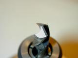
Tech Tip of the Month: Piston Rings
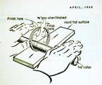
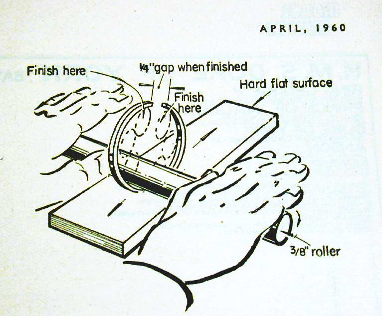
On the basis of having made precisely one set of piston rings, any claim I might make to knowledge on the subject must be viewed with a degree of skepticism. But I have researched the topic extensively, so the picture here virtually leapt off the page at me while leafing through the April 1960 issue of long-gone UK magazine, Model Maker (this is the magazine that originally published Arthur Weaver's Weaver/Ransom 1cc diesel).
What's going on? Well it looks like ring-gapping Jim, but not as we know it. In fact, it's about up there with that tantalizing Lindsay publication titled something like Embalming at Home for Fun and Profit! The drawing came from a series by Mr LVR Haydock titled, "OTTER Step by Step. A 15cc OHV engine". The verbatim text that describes the picture says:
Piston rings are made from phos. bronze, or you can use centrifugal cast iron if you prefer this.
How to make them
Machine a length of bar to 1.127 in. if your bore size is 1.125 in. (1 1/8in.) finished. Bore out to .998. Ring grooves must have 3 thou. clearance on depth, so when machining grooves go in 3 thou. deeper than .0625 (1/16 in.) depth or rings will ride on bottom of grooves and will cause trouble. Part off four rings to 1/16 in. wide, then with teeth ground off on edge side of junior hacksaw blade cut through ring, or you can snap the ring with a sharp small cold chisel to make the gap.
Take one ring and place on a 3/8 in. round bar. Place on hard surface and roll till gap opens out to about 1/4 in. keeping the bar rolling from end to end as sketched. This will give rings radial pressure. The ring gap should be 2-3 thou. (.002 ro .003 in.) when in cylinder bore; test ring gap by inserting in bore to check gap. File gap if it hasn't got the right clearance.
The quoted gap when closed is perhaps a bit low for cast iron rings. SIC sources say 0.004" of gap per 1.0" of bore, and this rule of thumb is confirmed by Chastain's Making Pistons book, reviewed here this month. Somehow I think a junior hacksaw blade, even with teeth ground off both sides, would result in a larger gap. As for the method of cold-forming the required ring tension, it seems crude but it would probably work, though I expect the rings would require a significant running-in period.
Compare this with the Trimble method which takes a lot longer, but results in rings that need no bedding-in at all. Never the less, I've now seen enough farm-yard engineering techniques that despite looking like applied butchery, work just fine. So let's not dismiss this one out of hand until someone tries it. Or if you already know that it works, I'd be happy to hear about it. For myself, I think I'll be sticking with Trimble's approach.
Speaking of Model Maker magazine, The Library is short four issues in the 1955/56 period, specifically:
- #52: March 1955
- #55: June 1955
- #56: July 1955
- #62: January 1956
I've got a lot of duplicates I can swap, or I'm even willing to pay! If you can help, please let me know. Incidentally, I noticed that the first volume of Model Maker (1951) contains an article by LC Mason; small world, isn't it?
Broken Link Report
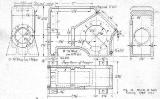
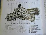
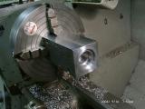
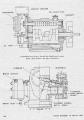
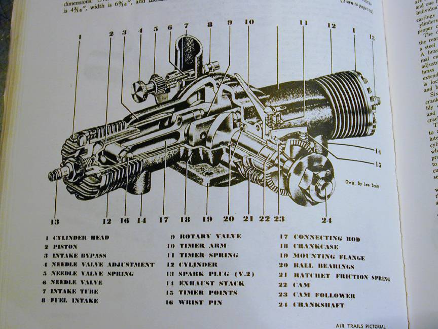
Stuff, as they say, happens. On this site, items occasionally become hard to find, or in the worst of cases, unreachable by any means. A Canadian reader alerted me to a broken link in the ET Westbury IC powered Road Roller pages. Investigation showed it was not so much broken as unfinished! In fact, over 30 pages of the series had never managed to get referenced. But all is fixed now, and double-checked forward and back. The road roller engine and its reversible, variable speed transmission are well worth looking over, even if land vehicles are not your thing. I can sort-of visualize how the main engine casting (pictured here) could be cored, but it would be a major undertaking. At least one of these has been built by fabrication; a task almost as daunting as making the required patterns! If anyone knows where a casting for one of these might be obtained, I'd be most grateful to hear about it.
 Model Engine Builder
 Editorial


