Editorial
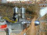
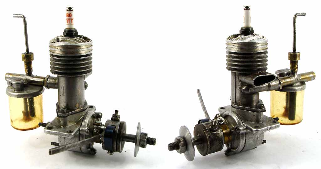
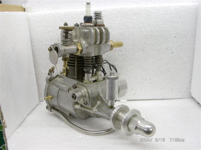
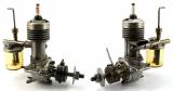 Our heading photo this month is a Madewell .147 being restored by Ken Croft. It's an American pre-war sparkie, circa 1940 and had a big brother .49 version. All Madewell's are now quite rare and can command astounding prices. The designer was Jack Keener and there is some evidence the engine was was revived as the Cobey-Waite .147 in 1946, though the resemblance is rather coincidental (prop at front; plug on top...). I hope that is correct, having come from an impeccable source (thanks Bert!) But if not, no problem, let me know—it's been over a month since my last crow feast, so I must be due for another.
The weather here is turning at last and it's downright pleasant in the shop, so I've managed to put a respectable amount of effort into the Feeney in the past month. As I write this, it's essentially complete apart from the piston rings and a pesky but potentially fatal problem that is preventing the inlet valve from sealing. This state was brought about by the way the valve openings had to be "machined", and to see why I've quoted that word, you'll have to wade through the latest episode of the construction saga. All in all, I like the Feeney and I can feel a four-stroke fixation coming on—having found that the period of engine appreciation and fondling that follows completion is greatly enhanced by being able to see little gizmos go up and down as the engine is turned over (I've never described myself as totally sane  ).
).
The hit counter for the month shows 7.25K hits, a little down on previous months, so I'd say we've stabilized. Reaction to the MEN Only CD has been favorable, and plans are now definitely in train. More when things firm up, but expect it about August. In the mean time, the site continues to grow. The count of pictures in the Feeney directory alone stands at 248 with quite a few more to come before it's done. All right, you can divide that by two to account for the thumbnails, but it's still a respectable number.
By the way, there are now only 22 months remaining until Microsoft produces the cure for Spam.
Warning! Computer Geeks Only...
Non-geeks may want to skip the next item.
There's a saying in computer science that goes something like "there's no problem in comp sci that can't be fixed by adding another layer of indirection" and how true that is. Last month I implemented a small, but hopefully significant and not annoying change to actually remove a layer of indirection (that's where something points to something that points to something else; you get there eventually, but you arrive "indirectly"). All my web pages contain metadata—"data about data"—which is rather appropriate, seeing as this is one of my prime research areas. The metadata contains keywords that lets robot crawlers like the things that index stuff for google dot com etc know the topics that might be on a web page. Any change is always a potential oops situation and this is what I hope I've avoided.
For several years, I've been referencing the individual "Editorial" pages through a page with the name "home.html" from the standard web entry point page "index.html". "Home" was the indirect way of reaching the latest editorial page, so "Index" never had to change and neither did the left side-bar navigation page. But I've discovered that this has had an unwanted side effect: on some search engines all my keywords were being indexed to "home.html" rather than say "ed.2004.04.html" which is the actual file name of this month's page. The net effect is someone using the index will be directed to what's on the current "home" page, when what they were expecting from their keyword search was an item that appeared on it at some time in the past when the index entry was made by the robot! I can't fix the past, or the inadequacies of someone else's crawler, but since last month, the "home.html" page is dead and the editorial page is referenced directly from the main web site page (index.html) and from the left side-bar "Home" button. I think I've re-jigged things so browsers will always update both automatically and hence, the main editorial page. If not, you won't be reading this!
GHS 7 Radial
 An unexpected surprise this past month was an email from Les Stone who's work has appeared here many times before. I continue to be amazed at the scope and quality of Les' projects. The subject here is the Hodgson 7 cylinder radial, initially designed by Clyde Garl. Here's how he described it:
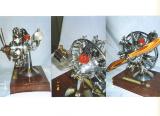
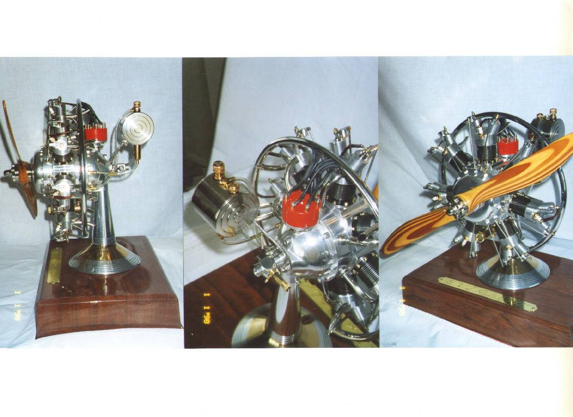
Your interesting article on Hodgson radials going all the way back to the late Sam Hodgson building one from Clyde Garl's 4 page plan in a 1936 Popular Aviation magazine prompted me to send along some photos of a single row 7 cylinder radial I completed in 1997. This one garnered 1st place at the April 1998 NAMES show in Detroit with Robert Washburn presiding.
I wanted it to look good so I got in touch with Woody Bartelt to see if he still had some of those gold plated Champion V spark plugs left. He did, and the rest is history. $18.00 each at the time. The early Merco 61 RC carb as you can see in the attached photos runs the engine well, with it's typical ruff sound just a little above idle, when the speed is increased gradually, it really starts to smooth out.
Again in looking at the photos, you can see my Clyde Garl influence ( I've had Clyde's 4 page engine plans for a number of years) in the base and pedestal. The base is a large thick piece of African Babinga wood. In Clyde's article, It mentions his base being that large in order to conceal an automobile coil, where as mine is just right to swing a Proctor 20" laminated propeller, although I also use an automobile coil and condenser. In reference to the pedestal, I did it a bit different than Clyde in that its totally turned and in 3 pieces with bronze sandwiched in between two alloy aluminum pieces (see photo). O K, the 7 cyl radial is built from Hodgson plans. This complete display comes in three flavors, hence from the subject matter above—G.H.S. in that order Garl, Hodgson and Stone.
I enhanced and embellished this engine with some thoughts of my own' off-setting the oil tank for a better view of the distributor. For the crankcase air breather, instead of being precariously drilled down through the center of the front crankshaft, I pressed a brass tube through right between the two cam lifters on top of the engine at number one cyl. I added more of a radius to the rocker arms for appearance sake.
The distributor cap is without the ears that stick out on either side and held in place with two 2-56 screws. The crankshaft is like the real world radials in that once the master-rod is put on, the shaft is keyed, so when the other section is added with Allen screw and slot sliding over key, the screw is tightened down so no movement whatsoever can take place.
This is an engine you need to study at length to really appreciate. It's obvious that the finish is excellent and the presentation well planned, but look at the little things—like the color contrast formed by the red distributor cap; the decorative treatment given to the petrol/oil tank ends; the chromed plug lead shielding. That first place was very well deserved, Les.
Tom Pasco's Six-stroke
Exactly 12 months ago, in the April 2003 Editorial I mentioned a web site describing the Beare "Six-Stroke" engine. I'd found the web site while running some tests on DSTC's Guidebeam search engine assist and naturally, had notified all the Motor Boys. Ken Croft in the UK mentioned it jokingly to his pal Tom Pasco (designer and builder of the 3 cylinder sleeve valve featured here in the August 2003 issue), suggesting it would be a good subject for a model. Well, guess what?
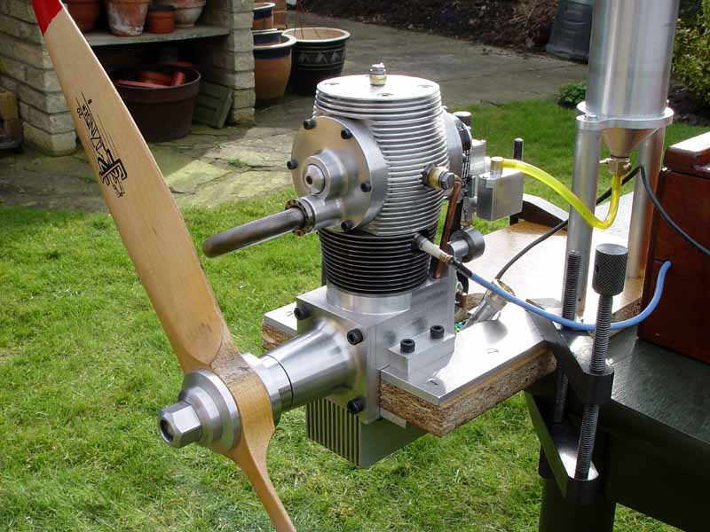
 Perhaps Tom didn't get the joke because he went ahead and built one. The "six stroke" tag comes from the design concept of the engine having two opposed pistons, one of which is running at half crankshaft speed (2 + 4 = 6). The Beare Technology Web site gives full details so I won't repeat them here. Here's Ken's words:
Remember my pal Tom Pasco who built the sleeve valve single, then the sleeve valve 3 cylinder radial. Well he has done it again. As a leg pull, I sent him all the stuff on the net about the Beare engine. If any of you followed up the link that one of the gang sent around, you will know that the Beare engine has a conventional plain bottom end, but at the top has a second piston working above the main cylinder, running at half the main crank speed. This upper piston uncovers ports like a 2-cycle engine but as it runs at half speed, the engine runs as a 4-cycle. The inlet and exhaust ports also have rotary Zimmerman valves so that asymmetrical timing can be used. Both pistons contribute to the total power produced.
I got a call today from Tom and we ran the engine!
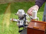
It not only runs well and sounds well, but it is also a handsome engine.
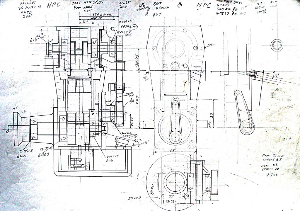
The details are 32mm bore and 25mm stroke for the bottom cylinder, 25mm bore and 10mm stroke for the top cylinder making I think 25cc total displacement.
The bottom piston has 2 conventional rings and the upper piston has a single Dykes ring. Lubrication is by a reciprocating pump in the wet sump, the engine running on neat gasoline with a Hall effect transistorized ignition system.
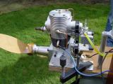
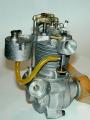
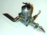
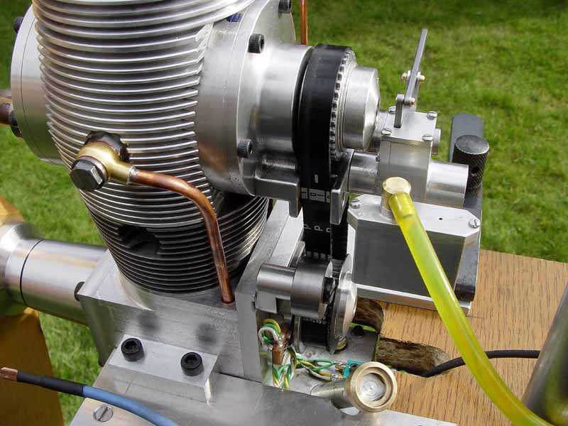
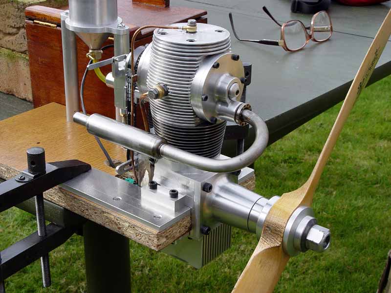
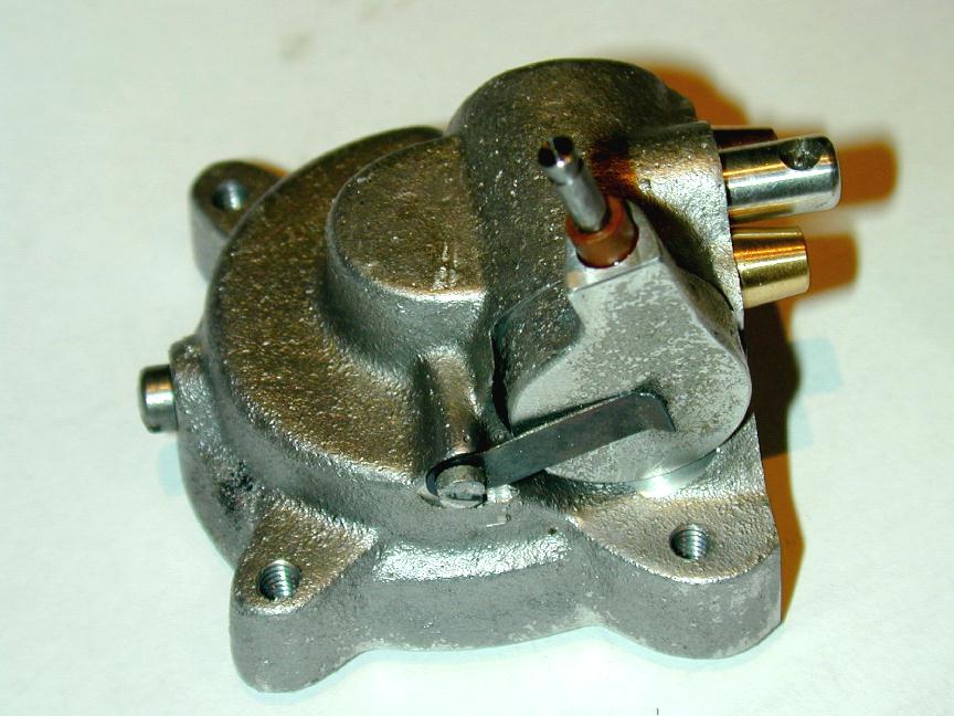
 A few fords of observation (mine, hence not necessarily accurate): The engine is fitted with a quite sophisticated lubrication system. As Ken mentions, an oil pump is the wet sump is delivering oil to both pistons via the copper pipes visible in these shots. The filler for the sump is visible poking up thru the engine mounting block in the lower right. In the close-up shot, the Hall-effect pickup can be seen nestled near the toothed belt driving gear on the crankshaft.
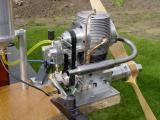
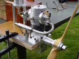 These photos show the carby details (of a type sometimes called "throttle body"; see Aero-Carb used on many aero-ized VW conversions). The chambers containing the inlet and exhaust Zimmerman valves are also plainly visible. The prop is a 20x8 Zinger.
And finally, before you ask , there are no plans suitable enough for building one of these available, nor are there any plans to make such plans available—sorry.
Feeney Nearing Completion
 The Feeney is now looking like a Feeney and the series continues to lag progress, but this month you can read about machining the cylinder casting and the trials, tribulations and outright mysterious goings-on encountered while trying to make a length of thin-wall steel tube. All this and more, as they say, in the Feeney Construction Log Page 5. But wait, there's more...
If you've been following the Feeney series, you may have noted that I've left the "Under Construction" GIF at the top of most pages. This indicates a suspicion that I'll have to revisit the page—ie, it's not finished (duh). Well, worst fears relating to the timer mounting were realized in last weekend of March, and the rear crankcase had to be re-jigged for earnest modification. You can visit Page 4 of the construction series to read the postscript that will be of importance to any prospective Feeney builder (and I still haven't removed the "under Construction" tag ).
Tech Tip of the Month
A small departure this month. Instead of a tip on making engines, we'll look at starting a compression ignition engine—the type most commonly called a "diesel" (I'll call them diesels from here on in, even though this is not strictly correct). This has been a frequently asked question, especially as most North American modelers may never have seen a diesel run, much less tried to start one themselves. And starting an engine you made yourself for the first time, if you've never started an engine of that type before is a significant challenge. As an aside, I demonstrated a Taplin Twin for a group in Portland OR once. I was flipping away, looking for the magic compression setting and got told that it was never going to start 'till I put a battery on it! Anyway, here's what I suggest, and naturally, other experts will have different advice...
- Mount the engine firmly and fit a fuel tank of about 30cc capacity such
that the feed pipe is about 1/2" above the engine centerline. Single cylinder engines vibrate and the more firmly it's bolted down, the easier it will be to establish the settings. Don't fill the tank yet. The reason for this is to prevent accidental flooding while we are trying to establish the initial comp setting (experts may and probably will ignore this precaution).
- Use a fairly large prop. A new homebuilt engine is probably going to be a bit tight, so we are after a bit of extra "fly wheel" effect to keep it running until the piston/liner start to bed-in. Long stroke diesels will swing enormous props. The humble Mill .75 (0.046 cuin) will swing a 9" prop—don't try that on your Cox Baby Bee 049. My Deezil replica of 2cc was initially started using a 14" prop and is quite happy turning a 12. In general, step up the diameter by a couple of inches on normal, and use a relatively low pitch, say 4 to 6". I like to use wood props for this as you can get more diameter for less weight (that diameter translates to more flywheel when running).
- Set the compression so it has a nice bouncy feel when flicked and does not seem hard at the compression point. Move the prop so that the exhaust is closed and squirt a small amount of fuel into the exhaust. Enough will remain on the opening edges to to the job. Flick over smartly two or three times. If it does not go "pop", advance the compression about 1/4 turn, and try again. You'll probably have to re-prime after 6 or 8 flips. We are trying to find the approximate contra-piston position where the compression is right for the mixture to self-ignite.
If the engine suddenly feels "hard" without having advanced the compression,
it is flooded. Just back off the comp and keep flicking while gradually advancing again. If you want, open the exhaust and blow into the engine to clear the flood (this process was a lot more fun in the bad ol' days when diesel fuel had amyl nitrate in it ).
If you can't get it to go "pop", there is something wrong with the engine,
or fuel. "Standard" diesel fuel in a simple mixture of equal parts castor oil, kerosene, and ether (the medicinal type). Smaller engines like extra ether. Commercial brews may contain one percent or so by volume of some diesel ignition improver. As mentioned above, when I was a kid, we could buy a little bottle of amyl nitrate at the local chemist (drug store), along with our ether and castor. Amyl nitrate is a heart stimulant, which may be why we instinctively liked blowing out flooded engines. Alas (or perhaps thankfully), those days are long gone.
- When you've found the point where it will go pop, and maybe even run for a second on the prime, close the needle valve and fill the tank. Having the needle closed during this ensures we don't accidentally fill up the crankcase. Now "choke" the engine: Open the needle one turn only and place your finger over the air intake while turning (not flicking) the prop through compression. Remove your finger just as the prop passes through compression (this gives maximum choking effect—leaving the air intake closed off as you continue to turn it tends to blow the fuel back up the line as all engines keep the inlet port open for quite a few degrees after TDC). If you don't see fuel drawn up the fuel line and into the engine during this operation, open another 1/2 turn and repeat until the fuel just enters the spray bar.
- Flick over smartly. You may exhaust prime too, but with the needle now open, it's very easy to flood the engine. Be ready to increase the compression when the engine fires. The running comp setting from cold may be 1/2 to 1 turn further on from the starting position (depending on the comp screw thread).
- If the engine runs then stops, open the needle another 1/2 turn, choke a
couple of times, and try again (back off the comp if you advanced it). Very
quickly you should find the needle and comp setting for sustained running. This process of sneaking up on the needle setting minimizes the chance of flooding the engine. After you become an experienced diesel hand, and know your engine, it can be ignored.
- Initial runs should be slightly rich and under compressed; ie, closing the needle, and increasing the comp should both increase the RPM. The engine will be making "brerp, brerp, brerp" noises as it runs—this is normal. Increasing the comp will increase the frequency until a sustained note is obtained—but don't do that yet. Run at least 3 or 4 tanks through like this at this setting. Time each full tank run. As the engine loosens up, it will run longer. If the engine stops before running the tank dry, maybe "loading up" just prior to stopping, you can try a bigger diameter prop. A too-tight shaft/bushing fit can also cause this. That will require more drastic cures.
- You will get an idea of how fast the engine is capable of running at the end of each tank as the fuel runs out and the mixture leans out. After 3 tanks or so, you can start leaning the mix and increasing the comp. Another indicator is the color of the goop that is coming from the exhaust. While it is dark (or even black), the engine needs to run rich. When it is close to clear, or just cloudy, you can begin to lean it out.
Some people say diesels are messy and smelly. Some think "Titanic" was a great movie too. It's all taste, and let me assure you, diesels, especially flooded ones, taste much better than glows!
New Books and Magazines This Month
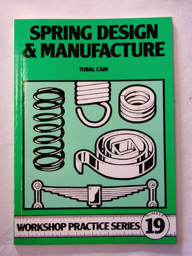
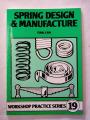 "Spring Design and Manufacture" is another in the Workshop Practice series published currently by Nexus (previously by Argus); ISBN 0 85242 925 8. Its author is Tubal Cain who we've spoken about before in the December 2003 Issue. This slim volume is packed with tables, graphs, nomograms, and illustrations providing more than you ever really wanted to know about the humble spring. Nearly all types are covered, including two chapters on leaf springs, reflecting the locomotive focus of Model Engineer magazine in which much of the material originally appeared.
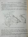
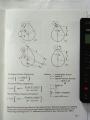 I mention this book this month because the last chapter talks about valve springs for internal combustion engines and it includes formulae for plotting tappet lift on conventional four-stroke engines using tangential and curved-flank cams; this being a subject dear to my heart as the Feeney progresses. If we assume a constant angular velocity for the cam shaft (ie, the engine is running at a constant speed), then knowing the height of the tappet at successive angles of rotation, we can easily calculate the velocity and acceleration of the tappet, and hence that of the valve. This in turn gives the spring force required to keep the follower on the cam. I recall that Tom Walshaw ("Tubal Cain") who designed IC cams as part of his day job, noted in a series on piston rings in the Model Engineer that the quickest way to derive the lift was draw it cam as big as possible and use a ruler and compass to measure the height to the tappet contact point every few degrees! All very interesting stuff that I'll go on a bit about some time in the future.
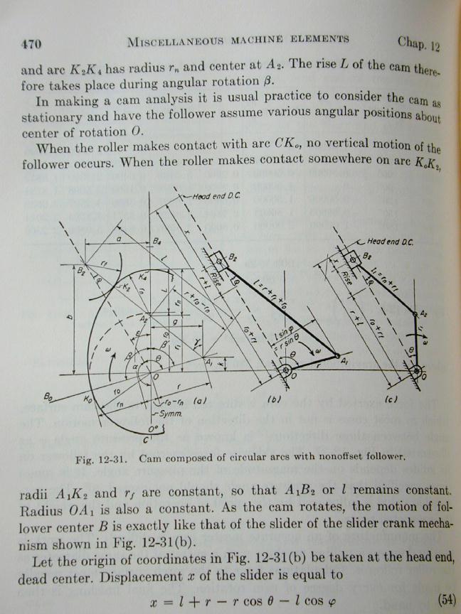
 On the same topic, while browsing through the flea-market that the University of Queensland runs each Wednesday, among the stalls selling crystals, incense, and granny-dresses to the students, I chanced on a book titled "Design of Machine Elements" by MF Spotts, from Prentice-Hall, 1961 (and apparently before ISBN became the norm for identifying books). As the asking price was less than a good cup of coffee, I forewent the coffee and bought the book.
 It's packed with all sorts of mechanisms and tables and formulas and yet more nomograms for all the things that electrical engineers never had to study. Included is yet another burst on calculating tappet lift on cams of the types encountered in IC four-strokes. The treatment is more detailed than material found in Tubal Cain's book as it contains the formulae for cams where the follower is rounded or flat. The feeney followers are both rounded and flat, so it will be interesting to see how much effect this has. I'll be adding it to the bag of code I've been writing that will, hopefully, someday grace this website in a way that lets you plug in numbers and see the graphic results without worrying about the math. Look for this in mid-winter when it's too cold to work late nights in the shop .
Engine Of The Month: The Kingcat
 I know, I know... Last month I said the feature engine was going to be the Hungarian Alags. What can I say? How about, it's like this, I lied and instead, you can read about the Kingshire Products "Kingcat". In researching the history of this engine, I knew adds and reviews had appeared in Aeromodeller, but when? Random searches were failing, when I suddenly thought of Clanford's A-Z. Sure enough, Clanford has a picture of a delux Kingcat and states it's year as 1979. Like a lot of entries in Clanford, close, but no banana. The actual year of introduction is 1977, but he'd put me in the ballpark sufficiently to find all the material I remembered seeing, someplace. As usual, click on the thumbnail pic to zot to the write-up, or use the Engine Finder.
Fallout
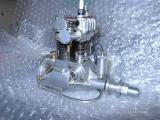
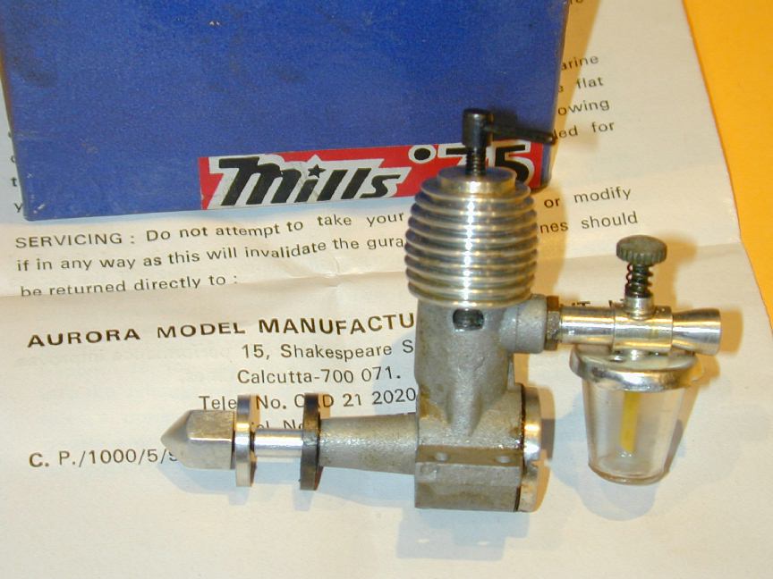
 As expected and anticipated, the fallout from the Christies auction of Miguel's collection continues as the lucky bidders dispose of the extra lot items they had to buy to get the single item they actually wanted. This is making some for whom bidding on the lot was not an option rather pleased. One of these is Eric Offen, who sent me a photo this month of the Edgar T Westbury "Kinglet" he has acquired in this way.
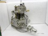
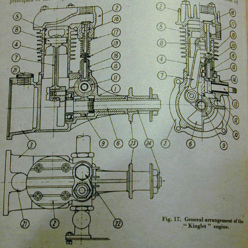
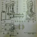 The Kinglet is a 5cc side valve four-stroke ignition engine. The design appeared in the Model Engineer, Volume 78, Issue 1936, published in 1938 (don't get confused). ETW says it shares some ancestry with the Kestrel, a 5cc two-stroke published the previous year, but apart from sharing the capacity and bulkhead mounting via an integral fuel tank, I'd say any resemblance is imaginary. In his "Four Stroke Review" series of 1945, Westbury describes it as a simple, compact design of moderate power, easy to start, docile, and exceptionally quiet. It uses skew gears to drive the valves and unlike the larger Westbury four-strokes which were fitted with ingenious, and miniscule but effective oil pumps, it required oil to be mixed with the fuel. The version of the Kinglet pictured above has a gravity oiler on the main bearing. The engine was probably made from pre-war castings and the workmanship of the unknown builder certainly appears to be of high quality.
 Eric has several original Westbury dies, rescued from some Welsh long grass several years ago, and has plans to perhaps produce Kinglet dies some day. This will be a challenge as the engine is a mere 5cc in capacity and the coring around the pockets that connect the side valves to the area above the piston are very intricate—a fact noted by Westbury in his post-war series on the development of model four-stroke engines. Like its stalemates, the Kinglet has a definite period charm and an intrinsic Westbury air to it. The odd thing next to the spark-plug is just a plug to block off the access hole to the exhaust valve (the inlet being inserted through the spark-plug hole). I'm starting to like little four-strokes more and more, and if castings were available I'd definitely add this little charmer to my list of must-builds.
Coming Next Month
With luck, the conclusion to the Feeney construction series, the Alag, and a travelling steady for small work (all forecasts subject to whim and last minute change).
 Warning! Computer Geeks Only...
 Editorial


