Editorial
There were just 65 hits short of 8,000 on this site last month. This is similar to previous months, so the number seems to have stabilized, but it's a good number. The weather here in Brisbane has been punishingly hot, with a run of five days where the over-night minimum was higher than the average daily maximum for this time of year. Sadly, heat was blamed for 23 deaths on the hottest day the month. I'm obviously building up to an excuse here, which is that not much was accomplished in the shop I'm afraid. Maybe this month, if I survive my birthday...
February seems to have been a bit of a radial month. Apart from the notice that Ageless Engines has moved, I received 3 emails about the Morton M5. One from the USA related the trials his uncle had gone through building a Morton from factory parts and drawings back in the late 40's. Another asked the all too Frequently Asked and Deeply Embarrassing Question of when am I going to get back to work on "my" Mortons and complete the construction series? The hold-up has been obtaining a small quantity of high-temperature anaerobic adhesive. My local supplier has closed their doors and I've simply not been sufficiently motivated to locate a new supplier (which hopefully should not be all that difficult). But as the Feeney also needs a couple of drops of this stuff, I'll have to address this lack in the next few weeks. After that, there will be no excuse not to pull the Mortons out from under the bench!

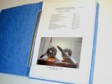
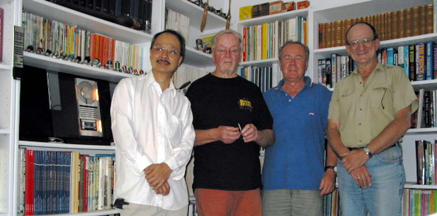
The Australian chapter of The Motor Boys International had an impromptu get-together this past month, which was a real buzz for all of us. Great tales were told and an old-time R/C field visited. Pictured opposite, from left to right are
Vincent Chi, GP and talented die caster of Battiwallahs,
Gordon Burford, designer and manufacturer of the Australian Taipan and Glow Chief engines (plus others),
David Owen, frequent collaborator with Gordon and designer of the fameous "Mate" extruded crankcase engine for home constructors (plus others),
and finally me, myself—impoverished academic and fearless wielder of excessive adjectives. The venue for the shot was my library, although we'd need a fish-eye lens to take in all the shelves. That's the Bambi Gordon's holding. If we'd been thinking clearly, he would have had a Taipan in his hands!
By the way, there are now only 23 months remaining until Microsoft produces the cure for Spam.
Ageless Engines Has Moved
 An email received this month from Lee Hodgson at Ageless Engines notifies that their web address has changed (the physical, postal location remains the same). Ageless produce plans for 7, 9, 14 and 18 cylinder radials, and a scale model of the Bentley BR2 rotary (larger than the Blackmore version mentioned a while back under Book of the Month). The new address is www.agelessengines.com and all links on this website under Links and Suppliers have now been updated, I hope. The drawings have undergone considerable evolution over time and the brief history on the Ageless site is worth a read. For more information, see this month's book review, and if you haven't visited before, there's a nice construction series on an adaptation of the basic Ageless design on the 5 Bears website.
An Italian Hodgson 18
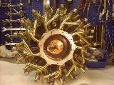 While mentioning the Hodgson radials, I noticed a couple of new entries on the Repliche E Riproduzioni Motori A Scoppio site this month, one of which is a Hodgson 18 cylinder. The site, maintained by Emidio Gattafoni is all in Italian, but that's what web translators are for. Besides, the links page describes my site as "magnifico sito di Ron Chernich con molti link", so I'll happily forgive them anything! Back to the subject: The workmanship, like everything on this site, is absolutely first class, and the photos, if a little small, show many of the construction steps and internal details. At least they load quickly. The engine is not yet complete, but it's getting close. I've linked the thumbnail shot here to the relevant page of the web site, but that page has a "back" button if you want to see the other projects the site contains. BTW: The completed engine with the metal three-blade prop at the top of the page is the one constructed by Lee Hodgson and if you look closely, you will see differences in the rocker covers and valve stem cooling fin arrangements. See this month's Book of the Month for more on this...
Feeney Constructions Continues
 Despite the record heat here Downunder in the past month, I've spent some time in the sauna, errr.. shop, making a few Feeney parts and trying hard not to exude corrosive fluids over the machinery. For some reason, the write-up is following even slower than actual construction, but never mind, photos have been taken and words can follow. This month the Feeney Construction page has had the Crankcase machining operations added to it.
Tech Tip of the Month
Yet another little task not often looked forward to with any relish is that of cutting the counterbalances into the crankshaft web (con-rod end profiling, 'shaft web cut-outs... is there any task we do look forward to?) I'll offer up my reason for this reluctance. Some parts take a lot of effort to produce, and effort equals time. As the process nears completion, the time investment is large and the opportunity to double the time taken by stuffing up the one in hand reaches a maximum—especially if some final operation requires a less than ideal set-up. Cutting the crank web cut-outs is one of those as it involves an interrupted cut coupled to a problem in workholding.
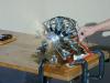
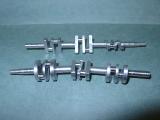
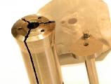
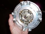
 The purpose of cutting a relief in the crankshaft web is to achieve static balance. It is impossible to achieve perfect dynamic balance on single cylinder engines like ours. The best we can expect is a reasonable compromise by attempting to counter-balance one-half of the reciprocating mass of the engine, namely the piston, wrist-pin, and conrod little-end [LCM]. This is generally achieved by removing metal from the web so that the crankpin will sit horizontal when a weight equal to one-half of the reciprocating mass is acting through the axis of the crankpin. The photo here (from the 5cc Sparey Project shows a shaft set on knife-edges with a donut of the correct weight slipped over the crank-pin. Sadly, even with massive cut-outs, the shaft is not within coo-ee of being balanced. At this point, one can try adding lightness to the piston, but then you run the danger of having an easily distortable piston and subsequent loss of compression. I've had compression punch the crown out of one such light weight piston—a most unnerving occurrence!
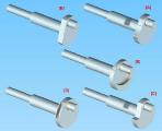
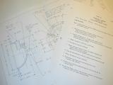
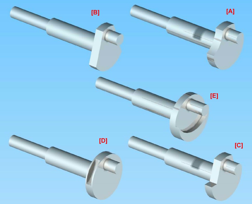
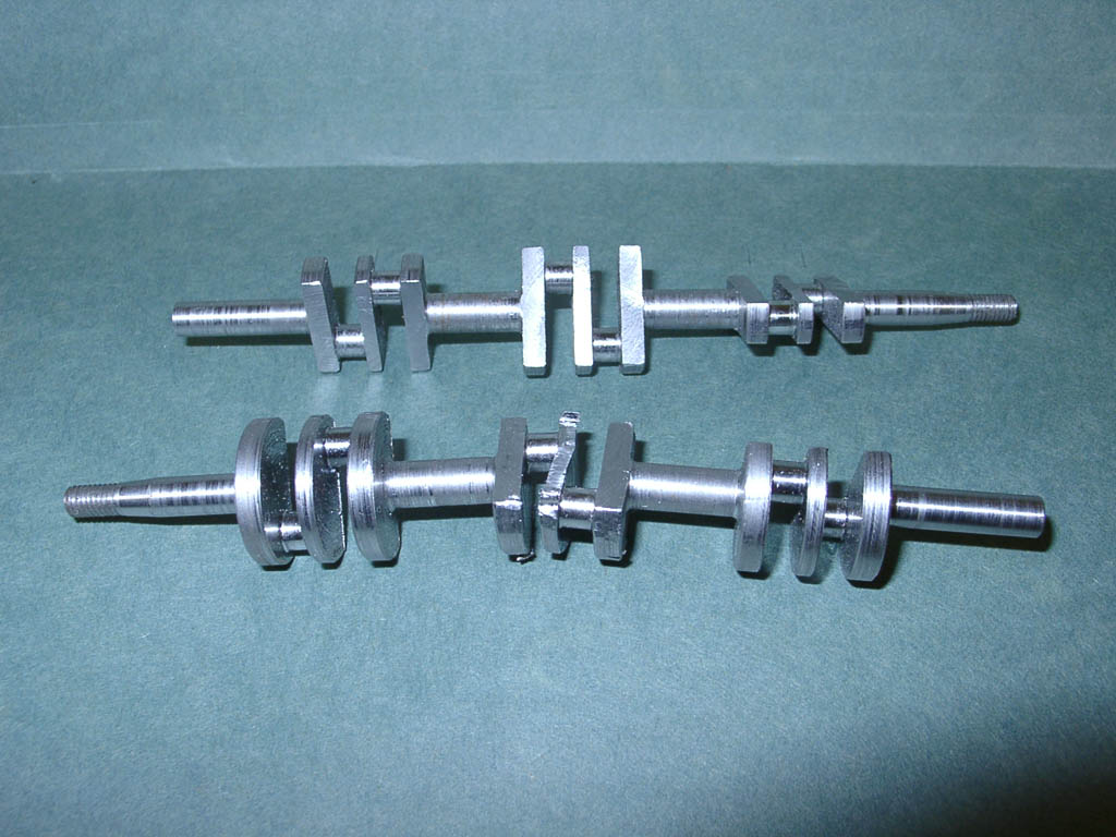
Obviously, the metal must be removed from the half of the crank web that carries the crank-pin. There are a number of ways of doing this; the picture here shows five of the most common approaches. I'll describe these before looking at workholding. The names used are in no way "official". I've made them up to be descriptive (I hope). Note there are other ways. These are merely the most common.
[A] Crescent Cut-outs
- A large diameter cutter is used to take a bight out of the web on either side of the crank-pin. The center of the arc is arranged to minimize the amount of metal near the pin, consistent with retaining some strength in the web. The lower extent will be on, or slightly below the diameter of the web. A variant on this scheme is to drill holes in the web either side of the pin. I've even seen old designs that advocate filling these holes with aluminum. The idea being to achieve mass reduction without volume reduction. Another variant is to drill the holes on the opposite side and plug them with lead, tungsten, depleted uranium, or some other easily obtainable heavy metal.
[B] Flat Segment Cut-offs
- This is similar to [A], but does not require a large diameter cutter and offers some other options for work holding. The key point on this approach, and that of [A], is that the cut-out can extend beyond the diameter line (shown just a trifle exaggerated in the 3D rendering) to improve balance. The reason is that up to a point, the amount of metal being removed by the cut on the "heavy" side is less than the amount being removed on the "light" side, so the ratio heavy to light continues to increase until that critical point.
[C] Obtuse Angle Cut-outs
- This is a variation on [B], that retains all of the mass on the "heavy" side of the web, so instead of an arc, we have an obtuse angle. The downside is machining is more complex and you need to be careful that the intersection is not so sharp that it induces cracking. The style was used on a lot of old sparkers, and some more recent designs as well. One extreme I saw on an old design reduced the obtuse angle to a right angle!
[D] Peripheral Crescent Cut-outs
- Yet another variation on [A], except the cut-out crescents are made in the edges of the web only. A thin ring is then generally shrunk over the web diameter to seal the edge. The objective is the have the effect of a full web on crankcase volume, while achieving some degree of balance. This approach has been used on commercial engines and high performance engines. It does require a thicker web than usual.
[E] Web Thinning
- A common "full-size" practice is to bolt (or otherwise secure) a weight onto the web opposite the crank-pin. Model designers frequently achieve the same effect by machining away the web concentric with the crank-pin. The result is more mass where we need it. Some designs supplement this with [A] or [B] type cut-outs. The down side is complication of the conrod profile to avoid having it clobbered by the counter-weight.
Now onto workholding for making those cut-outs. This is usually the last operation to be performed on the shaft, so the opportunity for an accident to ruin hours of work is at a maximum. Here's how Bert Streigler setup to make type [B] cut-outs. The shaft in question is a Brown shaft and the cut-out is per this pioneer engine design. Bert says:
-
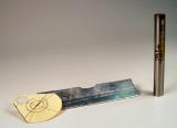
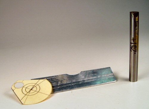
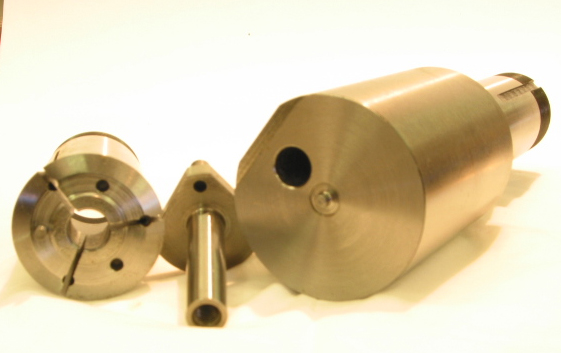
Here is a way I came up with. I don't have much in the way of measuring equipment, so I often resort to graphic set-up methods. One pic shows the little drawing, but I have since reverted to not even using that and simply do a drawing, then measure what pin is needed to get what I want. The three parts used in the set up are shown, and consist of a drawing to determine the pin size, a soft aluminum shield with a rather large cut out to allow the clamping of the crankweb without denting the inevitable radius where the web joins the shaft, and the required spacer pin.
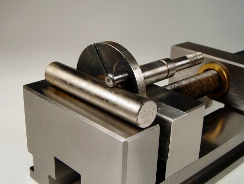
The second pic shows the set up. All I do is press down on the shaft to be sure it is in good contact with the top of the vise jaw, then roll it slightly until it is in good contact with the crankpin and then simply clamp down on it with the vise and machine. For the other side, just loosen the vise jaw slightly, roll the shaft the other way and clamp down again. This gives a perfectly symmetrical cut on both sides. All clamping is done on the web.
Ken Croft used a similar method for the crankshaft of the MS 1.24 (we don't always use the same method):
-

I don't know how you chaps do it, but when I have to cut slices off a crank disc for balancing, I so far have only a botched method for setting up. This has involved drawing the crank disc in TCad and printing it out. I then cut out the drawing, glue it to the disc and then set it up by eye under the mill. The results is a long way from perfect and I am never satisfied.
So as it is a job I now have to do on the MS 1.2 copy that I am making, I thought about it and realized just how simple the job really is to do perfectly.
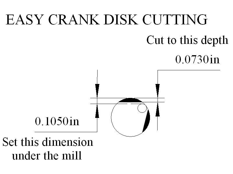
I drew the crank disc in TCad, then got TCad to take some measurements. I simply set the vertical pin to disc distance under the mill, using a flat ended probe and the downfeed register [I have a cheapo DRO on the mill].
I then end milled the required amount from the disc. I then rotated the disc and again set the pin to disc dimension the same as before, and removed an identical amount from the disc. The result is a perfectly symmetrical disc to exactly the required dimensions. Why did I not do it this way already?
Now I need to work out a simple method for scalloped cut-outs. That will not be so easy.
Bert and Ken have used two different measurement techniques to assure symmetry, but their basic approach is the same. We all agree that gripping the web in a mill vise is not without risk, especially if the crank is small. What goes unsaid between experienced model engineers is that the cutter should be sharp, the speed high, and the cut made so the teeth are meeting the work offset to one side to produce "conventional" milling (not "climb" milling). Even so accidents can happen to the best of us.
Clamping on the shaft affords the opportunity for a more secure set-up, but requires care not to injure what is probably a finely finished surface. Since cutter and shaft axes will be in-line using this setup, the cutter will be attempting to turn the shaft, opening us to just as much risk as before, unless a positive anti-rotation aide can be employed. Here's how David Owen made the segment cut-offs for the run of GB5's he and Gordon Burford produced.
-
I generally draw one-offs up on the crankdisc itself as you have done. Then I hold them in a 5c collet in the machine vyce. Level them up against the line and register the pin height above the table with my Vernier calipers. The actual dimension is meaningless. I trim down to the line as required and set the vertical stop. Then I turn the crank around until the pin is at the same setting on the other side, and cut down to the stop. I have used Bert's holding method but dislike it for the same reasons as your self.
On most cranks where the cut is a straight line diverging from the centre, removing metal below the centreline will result in greater loss above the centre, which is what we want. I've got the math somewhere for this, showing the limits.
On cranks which have a scallop, or parallel cuts off the flank, the diameter is the limit. On this sort of crank, I mount in the 5c collet again, but with the shaft vertical.
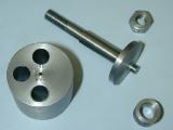
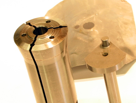
On production shafts I have always drilled an 1/8" hole behind the crankpin as a register. You will see the three 1/8" dowel holes in the attached 5c image, which shows the GB 5cc shaft. The centre hole locates the shaft for roughing out the crankpin from the original full depth disc.

So I end up with a square crankpin about 1mm larger than the finished diameter and with about .25mm to come off the crankdisc face. All shafts are completed to this stage. Then the dowel is moved to a side hole and and one flank machined away from each shaft.
The dowel is shifted to the other pin and the second flank is cut. The scruffy looking piece of shim keeps most of the swarf out of the vertical collet. The shafts are then chucked in the large 5c offset fixture in the Hardinge and the crankpin is turned to plus 0.2mm and the face cleaned up at zero. Then the shafts are hardened and finally ground.
The 3C collets used the way David has, are the bees knees for this job. The collet is keyed into the closer, so it can't rotate. Then the shaft is keyed to the collet with a 1/8" pin in shear (maybe hardened), so the shaft is not going to rotate, hence no teeth-clenching required. For one-off shafts, drilling a collet for the pin is probably out, but a correct sized collet exerts tremendous clamping force on the work, so this is still the best approach. By the way, look at the pin in the center of the offset crank turning fixture shown in the second photo. This will also prevent unwanted rotation of the shaft during crank-pin turning. Well worthwhile, especially if you're making 150 of them by hand!
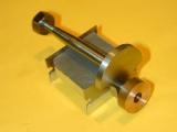
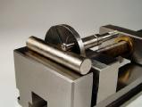
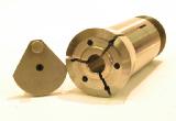
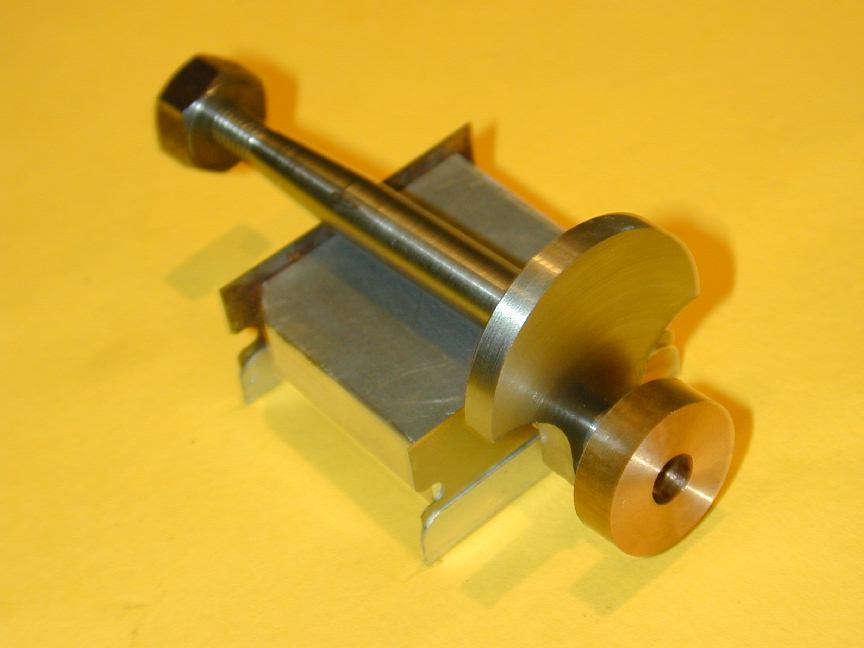
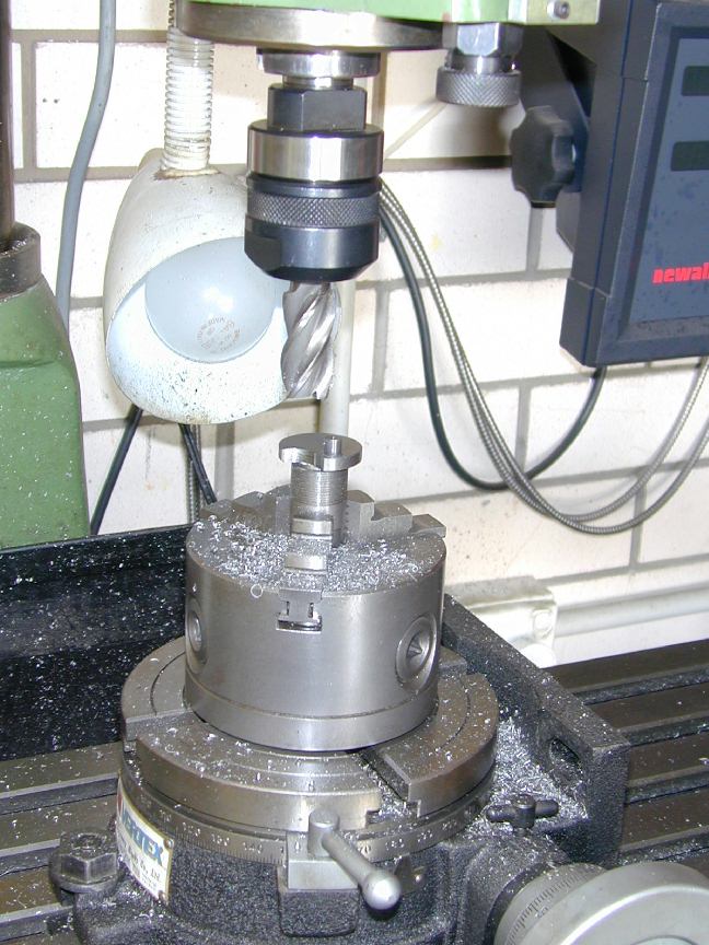
I generally make an offset fixture to hold the shaft for crank-pin turning. This fixture can double-up to hold the shaft while machining away the web (although 3C collets in a substantial holder would be far nicer, if I had any). The photo here shows the fixture made for the AHC Diesel that was re-used for the Sparey 5cc diesel. In this case, the shaft is secured by tightening up the prop nut, but a pin like David used with this 3C fixture would be good insurance. The holding fixture is gripped in the 3 jaw chuck, screwed to the rotary table mounted horizontally under the mill. It could also be held in the mill vise using a V-block.
 The crankdisk is marked for the cut-out using a template like Bert's. In the case of the AHC and Sparey, a 3/4" end-mill was the largest available, so that sets the crescent radius. The cutter is positioned to touch as much of the marked line as possible while stationary and the mill axes zeroed. I then "nibble" away the web from the outside in using the down-feed, moving one mill axis between cuts, and advancing no more than 0.030" at at time, with tightly clenched teeth. When the "zero" point is reached, the quill is locked down, then the sides of the cut are cleaned up by winding along one axis from zero, then back to zero and winding the other handle. A sharp cutter will do this smoothly. A dull one will shudder and bump, and try to snatch the work. Even a sharp cutter will raise a light burr at the edge of the cut. This is dressed off with a small grinding stone in the Dremel hand-tool—taking great case not to cause a run-away that hits the crank-pin (more teeth clenching required).
Examination of a *lot* of engines and drawings in the "sport" class shows that below 2cc (0.15 cuin), most experienced designers do not bother to cut away the web. My own experience supports this. The amount of vibration experienced by small engines is not great, and theory suggests that the lower crankcase volume resulting from a full web will make the engine a better fuel pump—though given the ability of small engines to flood up, this is not often a major concern.
References:
[LCM]
|
Mason, LC: Experiments with Small I.C. Engines, Model Engineer Vol 137 No 3430, June 7, 1971, Model and Allied Press, England, p 1152.
|
Goodbye PRIME, Hello GEARS
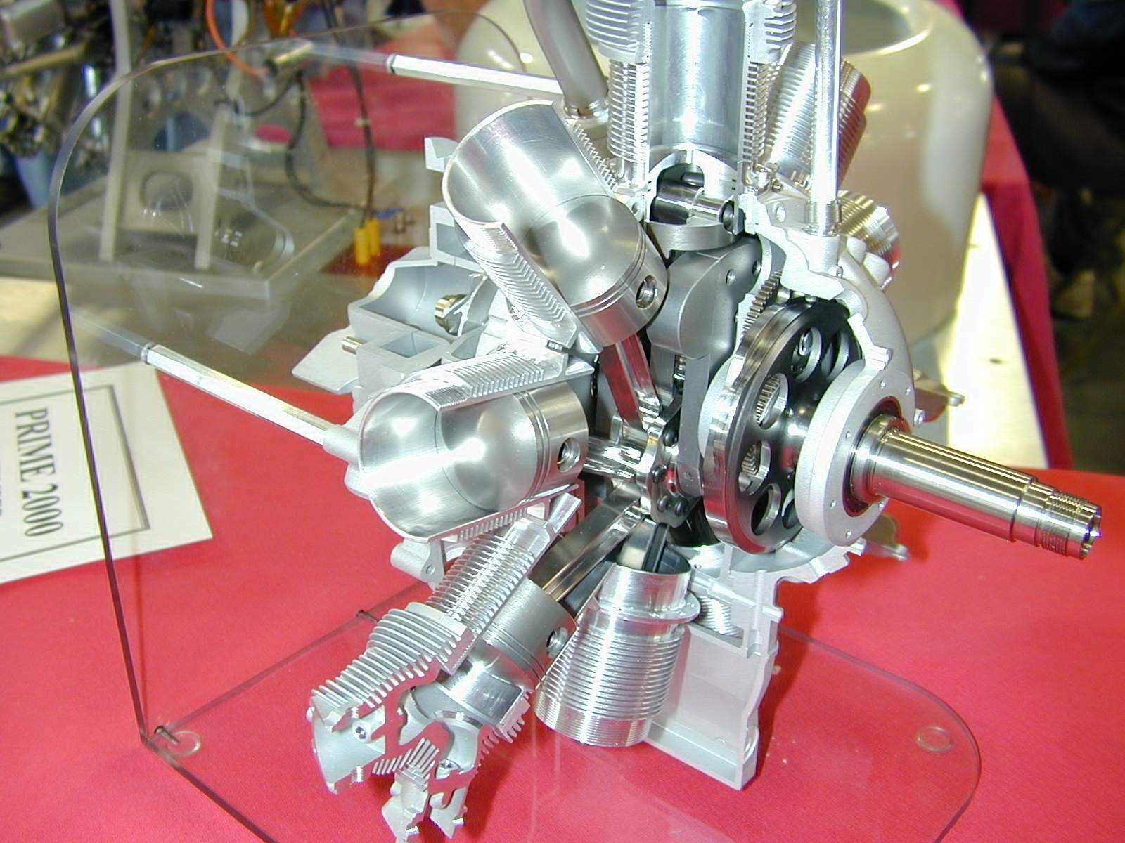
The premier model engineering show in the US is generally accepted to be NAMES (North American Model Engineering Society) held around April each year in the Detroit area since 1990. In 1997, a group of west coast model engineers decided to hold a similar show for the other side of the country. I was lucky to be living in Portland at that time and went along to the inaugural Pacific Rim Model Engineering (PRIME) exhibition in Eugene, OR, and then to be visiting Portland from Australia in '99 for the third show (photos on-line for '99 and I'll digitize the 35mm shots from '97 someday Real Soon Now). Sad news received this month is that costs of renting the exhibition hall compared to the return have forced the organizers to cut their losses. Some background on the show organizers and photos from PRIME '03 are available on-line at http://www.evmes.org/ (naturally, the photos include a Hodgson radial  )
)

However, all may not yet be lost for those in the Pacific north-west as another show to be known as "GEARS" (Gas Engine Antique Reproduction Society) is being planned at the Kliever Armory in Portland for September 25 and 26 this year. They too have a web site at http://oregongears.org/, though there's not a lot there as yet.
New Books and Magazines This Month
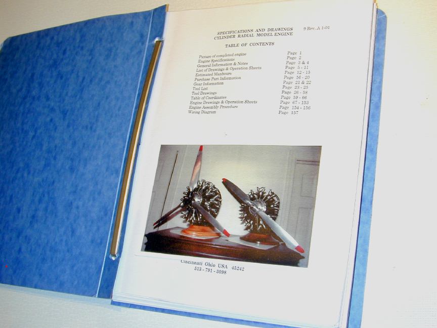
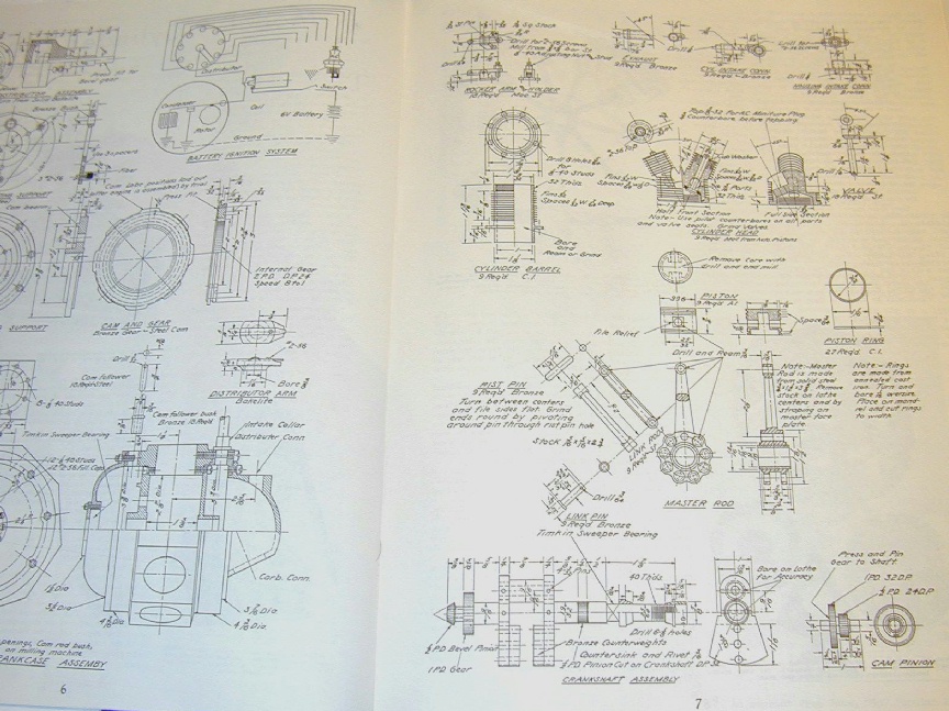
Since nothing "new" as such arrived into the library this month, and since I've mentioned the Hodgson radials a couple of times, it's probably appropriate to review the nine cylinder radial plans that sit on one of the lower shelves in the library (heavy things naturally go on the lower shelves to prevent premature shelf sag .) I won't describe the engine itself in any great detail, as that's very well covered by the Ageless site, rather I'll constrain myself (if possible!) to what you get in exchange for your US$85.
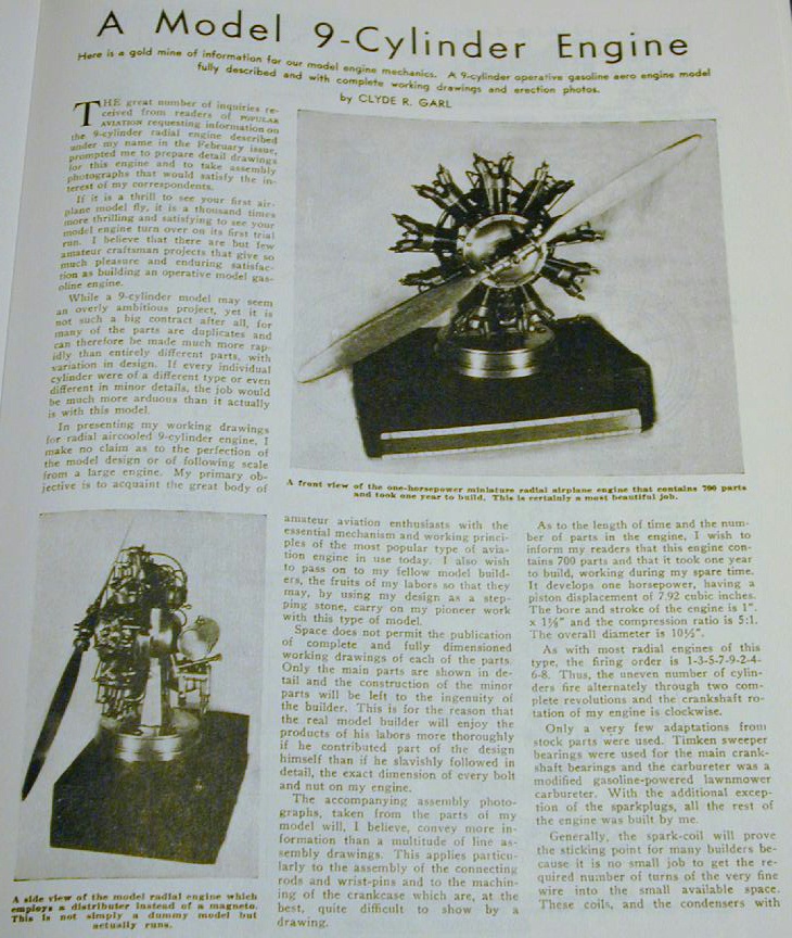
First, let's put an old, unwarranted criticism to bed. Although the engine is popularly known as the "Hodgson" radial and the plans say "designed by Samuel K Hodgson", neither Lee, not his late father Sam before him make any secret of the fact that the genesis of the designs lay in an article that appeared in Popular Aviation magazine of May, 1936 by Clyde R Garl. This article was reprinted in its entirety—all four pages of it—in Roger Schroeder's "Winged Engines" column in Engine Collectors Journal, Volume 8, Issue #41, copies of which you can order through the editor, Tim Dannels. The original article gives almost enough detail to permit an experienced and innovative engineer to build the engine. That's just what Sam Hodgson did in 1936. In accomplishing this, he had to work out a myriad of small but important details, like the lubrication system and other missing parts, and deserves the credit for this work and for making it available to the less experienced at a reasonable cost.
The other engines (7, 14 and 18 cylinder models) use the same cylinder assemblies and basic design features of the 9, but each have their own individual design differences. This required many hundreds of hours of design refinement that were worked out by the Hodgsons alone. Now there were no CAD stations about in the 1930's, so Sam's original plans were carefully hand drafted. All engines have subsequently been re-drafted by Lee using CAD, and expanded to include not just the drawings, but the tools, jigs, and machining sequences required to build the engines. What I'm trying to say here is that if you've heard any malicious stories relating to the provenance of the design, suggesting any improprieties, they are from an uninformed source. The plans contain truly significant effort by the Hodgsons, are fairly priced and represent value for your dollar—in my own humble opinion, of course.
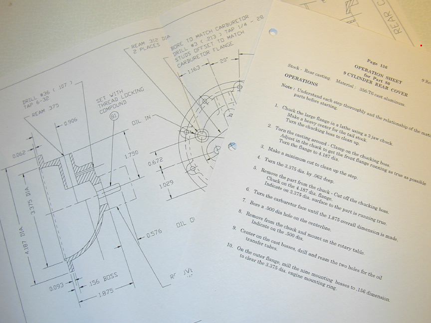
My plan set comprises 157 pages of plans and instructions. The pages are a mixture of 8.5 x 11 and 16.5 x 11 laser printed sheets. All sheets are three-hole punched and bound office-style between thick card covers with the larger sheets folded fan-wise to fit. Each page carries a revision number. From my initial examination, the plans are relatively error free. The only error I found in a reasonably complete walk-thru was an "out by 3" page cross-referencing error on page 59 that thoughtfully provides alternate coordinate drilling dimensions for parts where the plan page gives radius and angle dimensions—not hard to identify and correct. For all but the most trivial parts, each drawing is followed by an "Operation Sheet". This gives the material type and blank size required, followed by numbered machining instructions. The steps are terse, but more than adequate for any model engineer capable of tackling a project of this magnitude. In addition to the plans and operation pages, a table references each part by drawing number ID and name, with the number required and the estimated time to complete each part. Total time estimated is 1177.5 hours, excluding the time required to make the jigs and tooling. Another table lists the gears and bearings required by manufacturer's ID, and any special tools required with MSC stock numbers.
After the tables, drawings for the required jigs and tooling appear. The actual plans and operation sheets commence at page 67. The plans are drawn in 1:1, 2:1 and the occasional 4:1 scales. The sequence is roughly that which you would follow in building the engine, although my preference would be to start with the crankshaft—in case some minor accommodations need to be made in the crankcase components to match your shaft. The shaft is a fully fabricated assembly with a robust jig to align everything for final assembly using roll pins and peaned taper pins. The shaft is built in 6 pieces. One advantage of this is that an error will not result in a lot of lost effort. The cylinders use 12L14 leaded steel barrels onto which is screwed (permanently) an aluminum head. The mounting holes in the cylinder flange are drilled after the head is fixed to provide the correct orientation. Interestingly, the double bank engines have had (cosmetic) rocker boxes fitted while the 7 and 9 retain open rockers, per the Popular Aviation design. The highly practical, circular, finned valve stem cooling towers are rather unlike anything that has appeared on "real" radials. Many find this feature of the engine unattractive and several builders have gone to great trouble to emulate a more scale-like approach. For example, see this UK builder's 9 that uses pushrod sleeves and rocker covers to give the engine a more P&W look.
A significant change from the PA 9 is the addition of a "diffuser" in the aft crankcase section to assist even fuel/air mixture to the cylinder inlet pipes. No attempt is made to emulate a supercharger vane blower design, nor the annular cavity such a beast would require around it to add any benefit. I recall that Bob Roach, Australian designer of the scale P&W Wasp that Bruce Satra has made castings for tried gearing up the impeller to scale speed and finally concluded it added nothing beside stress on the whirling bits. The plans conclude with details of a test stand, fuel/oil tank, and make/break distributor system. Other builders have innovated here too, using solid state ignition systems.
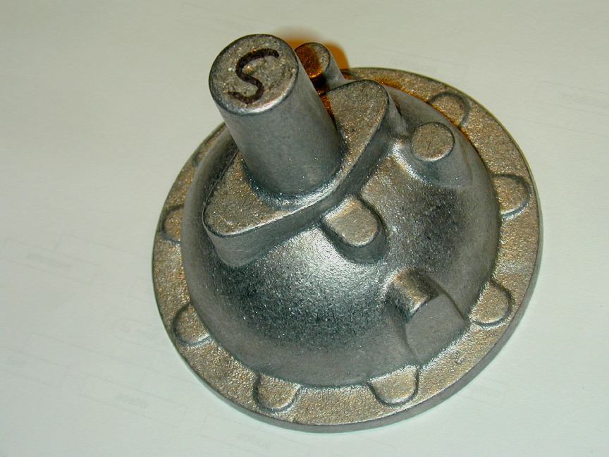
While no castings are really necessary to build the engines, Ageless does make a cast aluminum rear case cover available that will save a *lot* of effort as the protuberance that provides the mounts for the carburetor, oil pipes, and bevel gear driven distributor (2 for the dual bank engines) prevents the dome shape from being simply turned. The plans do not include any details for a suitable carburetor. Instead, builders are urged to purchase one ready made from a nominated supplier—probably a wise decision as this results in one less unknown in the equation when it comes time for the first run. So, if you think you'd like to build a nice, big radial, or just enjoy reading engineering plans and building it in your head, the plan sets from Ageless Engines provide quality and value for your dollar. Tell 'em Ron sent 'ya, and have your answer ready for when they say, "Who?"
Engine Of The Month: Allbon Javelin
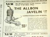 This month we do archaeology on the Aeromodeller stack to uncover what has been published about the Allbon Javelin Mks 1 and 2. Before joining forces with Davies-Charlton, Alan Allbon produced three elegant, light weight diesels; the Javelin, Spitfire, and Dart. All were preceded by a relatively short-lived glow called the Arrow. Read all about it by clicking the thumb-nail, or looking up the Javelin in the Engine Finder,
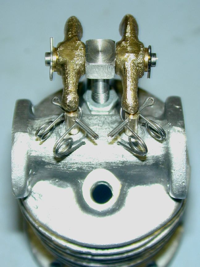
Update: Brian Perkins' Bristol Hydra
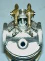
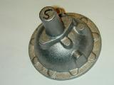
 There are a small group of model engineers scattered around the planet who accept no bounds when selecting full size engine subject for their working scale replicas. Many, having spent their working life with an engine manufacturer, concentrate on that manufacturer's engines. One of these is Brian Perkins who sent a brief email and photo this month showing the crankcase side of the bevel gear camshaft drive for his scale Bristol Hydra. Brian says the drive was assembled after a few problems with clashing teeth, which I can well imagine! I've added this to the Gallery, so click on the thumbnail for a brief explanation of what I think it is you are looking at, and a link to the larger photo.
Model Shop of Newcastle
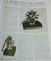
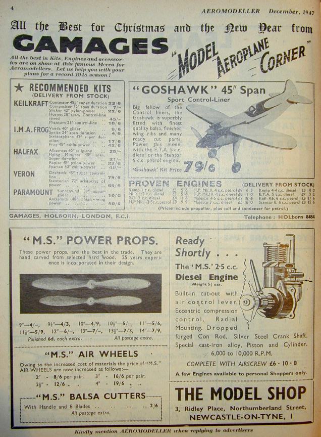
 Last month, when describing Ken Croft's latest engine, I casually mentioned the Model Shop of Newcastle-on-Tyne without knowing what hallowed ground I was treading. I've now discovered that said Model Shop is the longest lived Model Shop in the UK—and perhaps the world—tracing its existence from 1924 to current, although these days, the model product content has diminished and the toy content increased (a necessity to viability today). I'd even fitted, without realizing it, a pair of giant MS 3-1/2" pneumatic wheels to my Junior 60 back in the steam-driven R/C days of vacuum tubes and rubber driven escapements. The photo here from December 1947 Aeromodeller shows some of the products The Model Shop was then manufacturing and selling. Incidentally, the MS 1.24 diesel design has now been preserved as MBI style CAD drawings and a number of the Motor Boys are seriously thinking about building one, almost...
R&R
A site well worth visiting is the Radial and Rotary Engine Group hosted on Yahoo. This is an email discussion group dedicated to real (ie, round) model engines. Posts date back to November 2002 and cover all the popular designs available, including the Blackmore BR2, various SIC published designs, and the Hodgsons (I can't seem to escape that thing this month!) You'll need to join to access the photos and cooler stuff. There are currently 354 members—355 if they're unwise enough to let me in...
New Engines in the "Finder"
As well as the Allbon Javelin (this issue's Engine of the Month), the Allbon 2.8cc side-port diesel from 1948 and the ED Miles Special Marine Glow have been added to the Engine Finder. Thanks go to Bert Striegler and David Owen for these, and to Ken Croft for providing the ED as a fixer-upper.
The MEN Only CD Collection
Bet that got your instant attention . A regular reader (I now have at least two) emailed me with what we both thought was a good suggestion last month. This site—like space—is big, really big. Like mind-blowingly big, and browsing it on-line can be detrimental to your bank balance. The thought is to dump everything to a CD that can be bought from me for a nominal sum and browsed at leisure (WooHoo! At last! Ron makes a buck!) To sweeten the offering, I'll add some extra stuff not on the web site, like some emails from the late George Aldrich on a variety of engine related topics reflecting George's accumulated experience, and a genuine Motor Boys plan for a small diesel or two, ready for printing. If, and I say if I go ahead with this, it will be to the highest quality I can produce, so don't expect it next week. The price would be set in the UKP25, USD40 region, including air postage. So far, there is one person who thinks this is a good deal (excluding moi), so I'm not committing, nor taking orders at this time. But if you like this idea and think you may take up the offer, drop me an email. Oh, if you haven't figured it out yet, MEN = Model Engine News.
Coming Next Month
Machining the Feeney cylinder and valves etc, the Alag X3 and X4 (I hope!), and how to start diesels for fun and profit.
 Ageless Engines Has Moved
 Editorial


